Note : Les descriptions sont présentées dans la langue officielle dans laquelle elles ont été soumises.
CA 02371761 2008-09-23
Device With A Flexible Shaft For Removing Bone Grafts
The invention relates to an apparatus for harvesting bone
fragments as claimed in the precharacterising part of claim
1.
The implantation of endogenous bone material remains the
most efficient procedure for treating non united fractures,
pseudo-arthrosis, and for optimising the chances of success
in cases of arthrodesis. The utilisation of endogenous bone
material is safer and more efficient than the utilisation
of man-made hydroxyapatite materials or exogenous bone
fragments but, on the other hand, necessitates an
additional surgical intervention in the patient's body. The
scope of this intervention can be minimised by a limited
penetration and by the use of a cylindrical needle of the
type used for the removal of bone material for diagnostic
purposes. However, this technique is complicated and
implies a number of risks, as no precise control is
possible. For this reason the spongiosa is usually
chiselled out from the iliac crest through a large opening,
requiring a major skin incision. Special bone chip
collecting instruments make it possible to harvest
endogenous bone chips safely and rapidly, necessitating
only a small skin incision, so that the patient's strain
and injury can be minimised. These apparatuses safely
CA 02371761 2008-11-13
. =
2
remove bone material and may be used with a drilling
machine, thus allowing to harvest greater quantities with
better control and minimising the risk of an inadvertent
penetration of the cortical bone. This safe and efficient
technique makes it possible to harvest endogenous bone
chips for such purposes as fusions, pseudo-arthrosis and
fractures while injuring the donor as little as possible.
The removal of bone chips from the patient's body will
usually occur in the area of the pelvic bone. Other regions
for removing usable bone material are the proximal part of
the ulna or the distal part of the radius.
An apparatus of this type for harvesting bone material is
known, for example, from WO 97/39685 YUAN. This known
apparatus comprises a rigid, transparent shaft in the form
of a hollow cylinder wherein the bone chips are collected,
the quantity of collected chips being easily visible due to
the transparent shaft, a cutting head arranged on the one
end portion and means for receiving a turning moment
arranged on the other end portion of the shaft. The
apparatus is simply screwed into the bone, the cutting head
having the function of cutting and removing chips of bone.
The bone chips are received and collected in the cavity of
the shaft. The collected bone fragments are then, as needed,
removed from the shaft by means of a piston which is
inserted into the cavity of the shaft from the side opposite
the cutting head. As to the source of rotational drive
power, the apparatus may be driven by hand or by motor.
Another apparatus of this type for harvesting bone material
is known from US 5,556,399 HUEBNER. This known apparatus
equally comprises a drilling head with an adjoining, rigid
CA 02371761 2008-11-13
3
shaft in the form of a hollow cylinder where the bone chips
are collected and from where they are subsequently removed
by means of a manually actuated piston which is to be
introduced into the cavity from the side of the drilling
head.
A method and an apparatus for harvesting tissue is known
from US 5,403,317 BONUTTI. This known invention comprises an
apparatus for percutaneous tissue removal and includes a
drill shaft flexibly deformable with respect to bending, as
well as means for transmitting motion to the shaft. On the
front portion of the shaft, a cutting tip is mounted for
cutting tissue fragments from the tissue. During the cutting
process, the tissue fragments are removed along the shaft by
suction to a location outside the body.
Another device for harvesting bone material is known from US
4,646,738 TROTT. This known device comprises an exterior
tube-like part and interior tube-like part, whereby at one
end of the interior tube-like part a cutting tool is
attached. The interior tube-like part is rotatably arranged
within the exterior tube-like part, while the exterior tube-
like part is manufactured of a deformable material and is
selectively bendable.
Yet, another device for harvesting bone material is known
from WO 96/39956 AUST. This known device comprises a thin-
walled hollow cylindrical shank which is externally enclosed
through a spiral spring.
All these known apparatuses suffer from the disadvantage
that due to the torsional rigidity of the shaft there is a
risk of cutting or penetrating the harder cortical bone
CA 02371761 2008-11-13
~
3a
during the process of reaming the spongiosa lying between
said cortical portion of the bone.
The invention is intended to provide a remedy for this. It
is accordingly an object of the invention to develop an
apparatus permitting to ream the spongiosa between the
cortical bone in a simple manner without cutting or
penetrating the harder cortical portion of the bone.
According to the invention, this object is achieved by means
of an apparatus for harvesting bone chips which shows the
features of claim 1.
CA 02371761 2001-08-02
4
Further advantageous embodiments of the invention will be
characterised in the dependent claims.
The advantages achieved by the present invention consist
basically in the fact that the resilient deformability of
the shaft combined with a not too sharp-edged cutting head
make it possible to ream the spongiosa lying between the
cortical bone without running the risk, in doing so, of
cutting, or penetrating, the harder cortical portion of the
bone.
The apparatus according to the invention comprises a
hollow, cylindrical cutting tool including a hollow,
cylindrical cutting head which may have cutting bits and
cutting edges of various different shapes, a hollow,
cylindrical shaft with means for mounting said shaft on a
drive unit, and a drive unit which may consist, for
example, of a universal drilling machine. The configuration
of the cutting head and the shaft in the form of hollow
cylinders permits the bone chips removed from the spongiosa
by the cutting head to be received in the bore arranged
within said hollow cylinders. Adjoining the cutting head,
the shaft is resiliently deformable with respect to
twisting and/or bending.
This deformability may be achieved by a design of the shaft
in the form of a spirally wound sheet metal strip, of a
wire-reinforced plastic or rubber hose, or of a metal tube
with a bellows-type side wall.
The bit of the cutting head is preferably shaped in the
form of a calotte sector provided with a cutting edge. The
advantages of this configuration of the cutting head reside
CA 02371761 2001-08-02
in the fact that using a not too sharp-edged cutting head
or a cutting head provided with rounded edges makes it
possible to ream the spongiosa lying between the cortical
bone without running the risk, in doing so, of cutting or
5 penetrating the harder cortical portion of the bone.
According to a special embodiment of the cutting head, the
tip of the cutting head is shaped in the form of a calotte
including at least two through holes extending coaxially
and radially to the longitudinal axis into the cavity, the
edges of the through holes being equipped with cutting
edges for removing bone chips, and the removed bone chips
being conveyable to the cavity of the cutting head by means
of said through holes.
In other embodiments, the cutting tips may be shaped in the
form of cone sectors with cutting edges or in the form of
hollow, cylindrical milling cutters with front teeth.
The connection between cutting head and shaft may be
conceived as a detachable or a fixed connection, a
detachable connection permitting to have a smaller tool
set. Detachable connections may be realised in the form of
screw joints, radial tap bolts or radial pin connections.
In another embodiment of the apparatus according to the
invention a vacuum chamber is fixed to the driving element
in such a way that the hollow, cylindrical cutting tool
with its end portion situated opposite to the cutting head
leads to said chamber, the vacuum permitting the bone chips
to be conveyed in a simple way through the hollow,
cylindrical cutting tool into said chamber and to be
collected in said chamber. The chamber is provided with a
CA 02371761 2001-08-02
6
connection piece for connecting a suction hose permitting
to aspirate the bone chips. By means of the vacuum thus
created, the bone chips are aspirated through one or
several through holes arranged in the cutting head and
transported by suction into the bore arranged in the shaft,
from where they are conveyed through the entire length of
the cutting tool into the chamber. In order to prevent the
bone chips from passing into the suction hose, a separator
is arranged in the chamber for separating the bone chips
from the air flow. This separator may be realised in the
form of a filter, a sieve, a deflector or a cyclone.
This configuration of the apparatus according to the
invention makes it possible, without removing the cutting
tool, to convey the bone chips from the cutting tip through
the shaft away from the drilled hole and to harvest them in
a chamber located immediately adjacent to the cutting tool.
The chamber may be detached from the apparatus and the bone
chips are easily removable from said chamber, in accordance
with the surgeon's needs.
The vacuum applied to the chamber comprises a negative
pressure ranging between 0 bar and 1 bar, preferably
however between 0.2 bar and 0.8 bar.
In order to seal the bore extending through the shaft of
the cutting tool, said bore is preferably lined with a
rubber or plastic hose.
In the following, the invention and further developments of
the invention will be illustrated in greater detail with
reference to the partially diagrammatic representations of
several embodiments.
CA 02371761 2001-08-02
7
In the drawings:
Fig. 1 is a view of the cutting tool with a flexible shaft
in accordance with one embodiment of the apparatus
according to the invention;
Fig. 2 is a perspective view of the cutting head with a
flexible shaft in accordance with one embodiment of the
apparatus according to the invention;
Fig. 3 is a diagrammatic representation of one embodirpent
of the apparatus according to the invention; and
Fig. 4 is a diagrammatic representation of another
embodiment of the apparatus according to the invention.
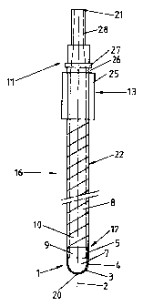
Fig. 1 represents the cutting tool 16 including a cutting
head 1 and a shaft 8. The shaft 8 comprises a portion 22
resiliently deformable with respect to twisting and/or
bending, and a portion 11 distant from the cutting head 1
and provided with means 13 for receiving a turning moment.
The means 13 consist of a hexagonal segment 25 and an
adjoining, cylindrical segment 27 provided with a groove
26. The two segments 25 and 27 may be mounted in a
corresponding chuck 15 (Fig. 3) of a drive means 14 (Fig.
3), the shaft 8 being releasably lockable within the chuck
15 (Fig. 3) with respect to axial displacement by means of
the groove 26 and with respect to rotational displacement
by means of the hexagonal segment. The bore 10 arranged in
the hollow, cylindrical shaft 8 penetrates said shaft 8 in
the direction of the longitudinal axis 2 beginning at the
cutting head 1 and extending right through to the end
CA 02371761 2001-08-02
8.
portion 21 located opposite to the cutting head 1, so that
the bone chips removed by the cutting head 1 may be
conveyed along the longitudinal axis 2 through the inside
of the cutting tool 16. The fixation of the cutting head 1
on the shaft 8 may be realised by means of set screws or,
for example, by means of spring bolts arranged between the
shaft 8 and the cutting head 1. The resiliently deformable
portion 22 of the shaft 8 is made of a spirally wound sheet
metal strip, the bore 10 being lined with a rubber or
plastic hose 36 (Fig. 4), said hose 36 ensuring a tight
sealing of the bore with respect to the ambient air.
Fig. 2 shows one embodiment of the cutting head 1. The
cutting head 1, realised in the form of a hollow cylinder
including a longitudinal axis 2 and a cutting tip 20,
comprises a front segment 4 adjoining the cutting tip 20
and a rear segment 5 distant from the cutting tip 20. The
front segment 4 consists of a hollow cylinder including a
cutting tip 20 shaped in the form of a calotte sector, the
side wall of the front segment 4 as seen in a cross-
sectional view at a right angle with the longitudinal axis
2 forming only a sector of an annulus, so that a through
hole 7 is formed which extends radially to the hollow,
cylindrical portion and axially to the cutting tip 20. The
side wall of the front segment 4 extending from the cutting
tip 20 to the rear segment 5 is realised in the form of a
cutting edge 3 leading to the through hole 7. As the
rotating cutting head 1 is drilled into the bone, bone
chips are removed by the cutting edges 3 and pass through
the through hole 7 into the cavity 9 of the cutting head 1
from where they are conveyed through the bore 10 arranged
in the shaft 8.
CA 02371761 2001-08-02
9
Fig. 3 shows a preferred embodiment of the apparatus
according to the invention. The cutting tool 16, which
serves for harvesting bone chips, consists of a cutting
head 1 with a hollow, cylindrical shaft 8 extending along
the longitudinal axis 2. This shaft 8 is locked with
respect to axial and rotational displacement in the chuck
of a universal drilling machine 30 serving as drive
means 14. The drive means 14 confer to the shaft 8 equipped
with the cutting head 1 a rotatory movement about the
10 longitudinal axis 2, causing the cutting head 1 to drill
itself into the bone and to remove the bone chips to be
harvested. The shaft 8, from the cutting head 1 to the end
portion 21 located opposite to the cutting head 1, is
shaped in a hollow, cylindrical form, so that the bone
15 chips may be conveyed along the entire length of the
cutting tool 16. In addition, a recipient for receiving the
bone chips, referred to as chamber 17, is fixed to the
drive means 14. Extending coaxially to the longitudinal
axis 2, the chamber 17 with its front end portion 24 is
releasably connected to the drive means 14 in such a way
that the end portion 21 of the cutting tool 16 located
opposite to the cutting head 1 leads to the chamber 17, the
point of contact between the two being realised in such a
way as to ensure a tight sealing with respect to the
ambient air. On its end portion 23, situated opposite to
the shaft 8, the chamber 17 is provided with a connection
piece 18 to which a suction hose (not shown) may be
connected. Due to the vacuum existing in the suction hose
the chamber 17 is equally evacuated, thus creating a
negative pressure inside the hollow, cylindrical cutting
tool 16 whereby the bone chips removed by the cutting head
1 are transported by suction through the interior of the
shaft 8 and into the chamber 17 where they may be
.,__ _.. -__ ~. ..... .. __....._ .. . ...__-.__
CA 02371761 2001-08-02
subsequently collected. In order to prevent the bone chips
from being carried along by the vacuum into the suction
hose, a separator 19, which in the preferred embodiment is
realised in the form of a filter, is arranged in the
5 chamber 17 in such a way that the bone chips are kept from
passing through the connection piece 18.
Fig. 4 shows another preferred embodiment of the apparatus
according to the invention. The embodiment of the apparatus
10 according to the invention shown here differs from the
embodiment shown in Fig. 3 only in so far as the cutting
tool 16 extends through the chamber 17 arranged coaxially
to the longitudinal axis 2 and that the means 13 for
receiving a turning moment imparted by the universal
drilling machine 30 are releasably connected with said
universal drilling machine 30 in the area of the chamber
bottom 33 located opposite to the cutting head 1. The
chamber 17 is releasably connected with the universal
drilling machine 30 by means of the chamber bottom 33.
Instead of a cover, the chamber 17 is provided with a
bearing housing 34 wherein the cutting tool 16 with respect
to its rotatory movement about the longitudinal axis 2 is
mounted for example by means of roller bearings 35, the
chamber 17 being sealed with respect to the ambient air by
means of an annular sealing 37. In addition, the connection
piece 18 for connecting a suction hose is arranged on the
side wall of the chamber 17. The sealing of the flexible
shaft 8 is realised by means of a rubber or plastic hose 36
lining the bore 10 of said shaft along the longitudinal
axis 2.