Note : Les descriptions sont présentées dans la langue officielle dans laquelle elles ont été soumises.
CA 02372018 2001-08-27
WO 01/47581 PCT/IB00/01954
1
METHOD AND DEVICE FOR MONITORING THE ACCESS TO THE
CARDIOVASCULAR SYSTEM OF A PATIENT
The present invention relates to a method and a
device for monitoring the access to the cardiovascular
system of a patient undergoing an extracorporeal
treatment of blood.
The invention is useful in any kind of treatment
in which blood is continuously withdrawn from a
patient, circulated and treated in a treatment device,
and returned, once treated, to the patient.
Hemodialysis, hemofiltration, apheresis and
plasmapheresis are examples of such treatment.
For the sake of clarity, the invention will be
described hereunder in relation to a specific
treatment, hemodialysis, to which however it is not
limited as will readily appear to the persons skilled
in the art.
A dialysis machine generally comprises.
- a filter (hemodialyzer) having a first and a
second compartments separated from one another by a
semipermeable membrane;
- an extracorporeal blood circuit, having an
arterial branch connected to an inlet of the first
compartment and a venous branch connected to an outlet
of the first compartment; a blood pump is arranged on
the arterial line and a bubble trap is connected to the
venous line;
- an dialysis liquid circuit, having an fresh
dialysis liquid supply branch connected to an inlet of
the second compartment and a used liquid branch
connected to an outlet of the second compartment.
In use, the blood of the patient and the dialysis
liquid are respectively circulated in the first and the
second compartments, generally in counterflow.
During a dialysis treatment, undesirable
substances (by-products of the metabolism, such as
urea, creatinine, etc.) contained in the blood migrate
across the semipermeable membrane from the blood
CONFIRMATION COPY
CA 02372018 2001-08-27
WO 01/47581 PCT/IB00/01954
2
compartment to the dialysis liquid compartment by
diffusion (dialysis phenomenon, strictly speaking) and
also generally by convection, a fraction of plasma
water being usually filtered during the treatment so
that the patient looses a few kilograms (so-called
"weight loss") corresponding to an excess of water
accumulated in the body between two treatment sessions.
Each branch of the extracorporeal circuit is
fitted with a needle (respectively, arterial needle and
venous needle), by means of which the extracorporeal
circuit is connected to the patient: just before
starting the treatment, the arterial needle and the
venous needle are inser~ed in the fistula of the
patient (portion of a vein surgically connected to an
artery) for respectively collecting the blood to be
treated and returning the treated blood to the
patient's cardiovascular system.
Disconnection of one of the aforementioned needles
from the fistula causes interruption of access to the
patient's cardiovascular system. Disconnection of the
venous needle, if not detected in time, has
particularly serious consequences, as it can cause
exsanguination of the patient. For this reason there
have been various attempts to provide methods capable
of detecting disconnection of the needles, and
especially of the venous needle.
One of these methods, which is based on the
electrical conductivity cf the blood, is described in
WO 99/12588. According to this method, the
extracorporeal circuit and the patient's cardiovascular
system are subjected to an electric current, and
changes in the current that are caused by the
disconnection of one of the needles or both of the
needles is detected, by means of measuring instruments
arranged along the extracorporeal circuit. The
measuring instrument used are inductive couplers, i.e.
coils arranged at prede~ermined locations along the
extracorporeal blood circuit.
CA 02372018 2001-08-27
WO 01/47581 PCT/IB00/01954
3
The method described above has various drawbacks.
In particular, although valid from the theoretical
standpoint, this method is not able to provide
satisfactory results from the practical standpoint,
because the high electrical impedance caused by the
peristaltic pump, which in fact interrupts the
continuity of blood flow, necessitates operating with
relatively high currents in order to make use of the
scant conductivity of the materials of which the
extracorporeal circuit, the dialyzer, the hose of the
peristaltic pump and the bubble trap are made (PVC,
polycarbonate). The use of relatively high currents is
certainly not advisable in a machine connected to a
patient and even if they were used, it would not be
possible to transmit these high currents by means of an
inductive coupler which, among other things, also
generates parasitic currents which disturb the
measurement. In some dialysis machines the bubble trap
also represents a high impedance of the same order of
magnitude as the peristaltic pump, and thus makes one
of the drawbacks previously described even more acute.
Therefore, in view of the fact that it is
advisable to operate with relatively low currents and
that the impedance of the peristaltic pump, and in the
majority of cases, of the bubble trap, is high, it
follows that disconnection of one of the needles causes
only slight changes in current, such as could be
confused with the background noise of the measuring
instrument.
Furthermore, this method does not take into
account that the patient might be connected to earth
and that the dialyzer itself is in fact connected to
earth, since the dialysis fluid circuit is connected to
earth in accordance with the provisions of the safety
standards relating to dialysis machines.
The aim of the present invention is to provide a
method that obviates the drawbacks of the prior art.
According to the present invention, a method is
provided for monitoring the access to the
CA 02372018 2001-08-27
WO 01/47581 PCT/IB00/01954
4
cardiovascular system of a patient undergoing an
extracorporeal treatment of blood in a machine
comprising a treatment device and an extracorporeal
circuit having an arterial branch and a venous branch,
the arterial branch having a first end fitted with an
arterial needle to be inserted in the vascular system
of the patient and a second end connected to an inlet
of the treatment device, and the venous branch having a
first end connected to an outlet of the treatment
device and a second end fitted with an venous needle to
be inserted in the vascular system of the patient,
the method being characterized in that it comprises the
steps of:
~ generating a potential difference between a first
point of the venous branch and a part of the machine;
~ detecting the value (dV) of a quantity that
correlates with the electric current along at least one
section of the venous branch between the first point
(B) and the venous needle; and
~ comparing the detected value (dV) with a reference
range ( I ) .
The present invention relates, in aaaizion,
monitoring device.
According to the present invention, a device is
provided for monitoring the access to the
cardiovascular system of a patient undergoing an
extracorporeal treatment of blood in a machine
comprising a treatment device and an extracorporeal
circuit having an arterial branch and a venous branch,
the arterial branch having a first end fitted with an
arterial needle to be inserted in the vascular system
of the patient and a second end connected to an inlet
of the treatment device, and the venous branch having a
first end connected to an outlet of the treatment
device and a second end fitted with an venous needle to
be inserted in the vascular system of the patient,
the device being characterized in that it comprises:
CA 02372018 2001-08-27
WO 01/47581 PCT/IB00/01954
~ a voltage generator for generating a potential
difference between a first point (B) of the venous
branch and a part of the machine;
a detector for detecting the value (dV) of a quantity
that correlates with the electric current along at
least one section of the venous branch between the
first point (B) and the venous needle;
calculating means for comparing the detected value
(dV) with a reference range (I).
The invention will now be described, with respect
to the appended drawings, in which:
~ Fig. 1 is a schematic representation of a dialysis
machine connected to a patient and equipped with a
monitoring device according to the invention;
~ Fig. 2 is a schematic representation of a dialysis
machine connected to a patient and equipped with a
variant of the device in Fig. 1; and
~ Fig. 3 is a schematic representation of a dialysis
machine connected to a patient and equipped with
another variant of the device in Fig. 1.
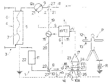
In Figs. l, 2 and 3, the number 1 indicates a
dialysis machine connected to a patient P. The machine
1 comprises an extracorporeal blood circuit 2 and a
dialysis fluid circuit 3 which pass through a dialyzer
4, which comprises a blood compartment 5 and a dialysis
compartment 6 separated by a semipermeable membrane 7.
The extracorporeal blood circuit 2 comprises, in
addition to the compartment 5 of dialyzer 4, an
arterial branch 8, along which a peristaltic pump 9 is
arranged, supplying a blood flow Qb, and a venous branch
10, to which a bubble trap 11 is connected. Arterial
branch 8 has a needle 12 which, in use, is inserted in
a fistula of patient P to collect blood from the
cardiovascular system of the patient P, while venous
branch 10 has a venous needle 13 which, in use, is
inserted in the fistula for returning the treated blood
to the cardiovascular system of patient P. Arterial and
venous branches 8 and 10 are tubes made of a plastic
material, generally PVC, as well as bubble trap 11.
CA 02372018 2001-08-27
WO 01/47581 PCT/IB00/01954
6
Dialyzer 4 is also made of plastic material, the
housing of it generally of polycarbonate.
In Figs . l, 2 and 3, machine 1 is equipped with a
device 14 for detecting disconnection of needles 12 and
13. The principle of the device 14 is based on the
electrical conductivity of the blood and on data found
experimentally that showed that circuit 2 made of PVC
can be regarded as an insulator and that both the
peristaltic pump 9 and the bubble trap 11 can be
regarded as concentrated impedances designated Z1 and
Z2 respectively. Peristaltic pump 9 cyclically
interrupts the blood flow Qb. at each half-turn of the
pump 9 and accordingly the impedance Zl is a function
of the number of turns of pump 9 and of the supply
frequency. Experiments have established that the
impedance Zl is between 500 and 2000 kS2. The impedance
Z2 is determined as well by the fact that the blood
flow Qb is interrupted in the bubble trap 11 and the
value assumed by Z2 is also between 500 and 2000 kS2.
Recent designs of bubble trap have a relatively low
impedance, which is negligible with respect to the
impedance Z1. This circumstance will be borne in mind
when describing the operation of device 14.
The impedances of the other components of
extracorporeal circuit 2 are negligible with respect to
the values of impedance Z1. To evaluate the operation
of device 14, it is necessary to bear in mind that the
dialyzer 4 is connected to earth via the dialysis fluid
circuit 3 and that the patient P may be connected to
earth (R - 0) or insulated (R - infinity) or in a
situation intermediate between the two preceding
limiting situations. These distinctions are important
as it would be difficult to prevent the patient P from
moving, for example resting a foot on the floor or
placing a hand on the bedhead of an uninsulated bed,
thus altering the configuration of the possible
electric circuits defined by the machine l, the patient
P, and device 14.
CA 02372018 2001-08-27
WO 01/47581 PCT/IB00/01954
7
In Fig. l, device 14 comprises a control unit 15,
a generator 16 connected to arterial and venous
branches 8 and 10, a detector 17 of a voltage drop and
a clamp 18 arranged along venous branch 10. Generator
16 is connected respectively by two conductors 19 and
20 and by two capacitive couplers 21 and 22
respectively to arterial branch 8 and to venous branch
10. Detector 17 is connected by two conductors 23 and
24 and by two capacitive couplers 25 and 26 to venous
branch 10 for detecting the voltage drop along a
predetermined section l0a of branch 10. An optimum
filter FO is arranged along conductors 23 and 24 for
minimizing the effect of noise on the input of detector
17, which is connected to control unit 15 for
transmitting a value dV indicating the voltage drop in
section l0a to unit 15, which compares this value with
a threshold value dVT. If the value detected is not
inside a range I around the threshold value dVT,
control unit 15 emits a control signal S for stopping
pump 9, a control signal G for closing clamp 18 and a
signal T for emitting a visible and/or acoustic alarm
signal.
Capacitive couplers 21, 22, 25 and 26 are made
with respective metal tubes 27, which are connected to
the respective conductors 19, 20, 23 and 24 and are
arranged around portions of the respective PVC tubes.
From the electrical standpoint, tube 27 defines a first
plate of a capacitor, the PVC tube defines the
dielectric, and the blood inside the PVC tube defines
the second plate.
Capacitive coupler 21 is arranged on arterial
branch 8 at a point A between the arterial needle 12
and the peristaltic pump 9, while capacitive coupling
22 is arranged on the arterial branch 10 at point B
between bubble trap 11 and needle 13. Detector 17 is
connected to venous branch 10 at points C and D, both
of which are between point B and the venous needle 13
and define the end of section 10a.
CA 02372018 2001-08-27
WO 01/47581 PCT/IB00/01954
8
When the patient is insulated (R infinite) and
impedance Z2 is high, the operation of the monitoring
device 14 according to the invention is as follows: the
blood being circulated in the extracorporeal circuit 2
in the direction indicated by the arrows in Fig. l, a
potential difference is applied between venous branch
and arterial branch 8 by means of generator 16 and
the respective capacitive couplers 21 and 22. This
potential difference generates a current between a
10 section of venous branch 10 and a section of arterial
branch 8 which is closed by the cardiovascular system
of the patient P on account of the high impedances Zl
and Z2 on the other portion of circuit 2. Detector 17
detects the voltage drop along section l0a of arterial
branch 10 and stores a value indicating the voltage
drop as threshold value dVT, determines the range I of
acceptability around the threshold value dVT and checks
whether the successive values dV are inside range I.
When one of the needles 12 and 13 accidentally
becomes disconnected from the fistula, the detector 17
detects the cancellation of the voltage drop dV in
section 10a, and the control unit 15 emits signals S, G
and T for stopping the peristaltic pump 9, closing the
clamp 18, and emitting an alarm signal.
The monitoring device 14 is particularly
advantageous because it by-passes the impedances Zl and
Z2, and the dialyzer 4 which is connected to earth.
Therefore it is possible to work with relatively low
currents since disconnection of one of the needles 12
and 13 represents an appreciable change in the current
along a circuit comprising a portion of the arterial
branch 8 and a portion of the venous branch 10, the
conductors 19 and 20 and the cardiovascular system of
the patient P.
When the patient P is connected to earth (R = 0) ,
if the venous needle 13 becomes disconnected, there is
no current flowing through the venous branch 10 and
therefore detector 17 detects a voltage drop equal tc
zero as is the case when patient P is insulated. If the
CA 02372018 2001-08-27
WO 01/47581 PCT/IB00/01954
9
arterial needle 12 becomes disconnected, there is a
voltage drop in section 10a, which is a function of the
impedance Z1 of the peristaltic pump and is therefore
significant owing to the high value of impedance Z1.
When 22 is negligible, disconnection of venous
needle 13 is detected both when the patient is
insulated (R infinite) and when he is connected to
earth (R - 0), as preferential flow of current occurs
along the portion of extracorporeal circuit 2 on the
side of patient P.
In the embodiment of Fig. 2, there is no
capacitive coupler 25 since point C coincides with
point B, whereas point D is located close to the venous
needle 13. In this case, detector 17 detects the change
in voltage along a section lOb, which is a section of
branch 10 between point B (i.e. C) and, essentially,
the venous needle 13.
When the patient P is insulated (R infinite) and
Z2 is high, the current circulates through conductors
19 and 20, a portion of the venous branch 10 and a
portion of the arterial branch 8. Disconnection of one
of the needles 12 and 13 has the effect that the
voltage drop is cancelled along the section lOb and the
patient P.
When the patient P is connected to earth (R = 0),
a disconnection of the venous needle 13 causes the
cancellation of the voltage drop as in the preceding
case, whereas when the arterial needle 12 is
disconnected, the voltage drop becomes a function of
the impedance Zl as in the preceding case.
When Z2 is negligible, the considerations relating
to the variant in Fig. 1 apply, except that the greater
length of section lOb relative to section l0a makes it
possible to refer to high values dV, at equal current
passing through the venous branch 10, and therefore the
device 14 is more efficient, as it increases the
difference between the value of the voltage drop dV
determined by the condition with the venous needle 13
connected and the zero value of dV.
CA 02372018 2001-08-27
WO 01/47581 PCT/IB00/01954
According to a variant that is not shown, again
the capacitive coupler 26 is omitted and is replaced
with a conductive bracelet, not shown, connected
directly to one wrist of the patient P. The operation
5 of the said variant that is not shown does not differ
substantially from the variant in Fig. 2.
According to the variant in Fig. 3, capacitive
coupling 21 to the arterial branch 8 is omitted, since
generator 16 is connected to earth via conductor 19,
10 and detector 17 is connected to the venous branch 10
via conductor 23 and the capacitive coupler 25 at point
C and to the arterial branch 8 via conductor 24 and the
capacitive coupler 26 at a point F between the
peristaltic pump 9 and arterial needle 12.
In use, when the patient P is insulated (R
infinite) and the impedance 22 is high, the value dV of
voltage drop along section lOc of the venous branch,
section 8c of the arterial branch 8, and the
cardiovascular system of the patient P is detected.
Section lOc is between point C and arterial needle 13,
whereas section 8c is between point F and venous needle
12. Disconnection of one of the needles 12 and 13
causes cancellation of the voltage drop.
When the patient P is connected to earth (R = 0),
a disconnection of the venous needle 13 causes the
cancellation of the voltage drop, whereas a
disconnection of the arterial needle 12 does not cause
any appreciable change in the voltage drop dV.
When the impedance Z2 is negligible, a low current
will pass along section lOc, however section lOc along
which the voltage drop dV is determined is relatively
long and therefore a detection thereof is significant.
In practice, all the variants of the monitoring
device 14 described with reference to the Figs. l, 2
and 3 enable a reliable detection of the disconnection
of the venous needle 13, since a disconnection of the
venous needle 13 causes, both when the patient P is
insulated (R infinite), and when the patient is
connected to earth (R = 0), a significant change in the
CA 02372018 2001-08-27
WO 01/47581 PCT/IB00/01954
11
value dV of voltage drop, in comparison with the
situation in which the venous needle 13 is connected.