Note : Les descriptions sont présentées dans la langue officielle dans laquelle elles ont été soumises.
CA 02372319 2002-02-19
a
- 1 -
NEEDLELESS HYPODERMIC INJECTION SYSTEM, APPLICATION DEVICE
AND MEDICATION CARTRIDGE THEREFOR
FIELD OF THE INVENTION
The invention concerns a needleless hypodermic injection
system for injecting a liquid medication.
The invention also concerns a reusable application device
which is a first part of such a system.
The invention further concerns a disposable medication
cartridge which is a second part of such a system.
BACKGROUND OF THE INVENTION
Prior art systems and devices of the above mentioned kind
have important disadvantages. They have a complex structure
and are therefore not easy to assemble and to use, in
particular for patients which have some handicaps or are not
in full possession of their handling capabilities. Moreover
they lack reliable means for preventing accidental release
of injections and their negative consequences, e.g. loss of
expensive medications and possible injures inflicted to the
user.
The main aim of the instant invention is therefore to
provide a system an application device, and a medication
cartridge of the above mentioned kind with which the above
mentioned drawbacks can be eliminated or at least
substantially reduced.
SUMMARY OF THE INVENTION
CA 02372319 2002-02-19
- 2 -
According to a first aspect of the invention the above
mentioned aim is attained with a needleless hypodermic
injection system for injecting a liquid medication, which
system comprises:
(a) a disposable cartridge~which contains a medication
and which includes a propellant and an igniter, and
(b) a reusable application device which comprises a
pressure chamber for receiving said cartridge, and actuation
means including an ignition system and means for ensuring
reliability and safety of the system.
According to a second aspect of the invention the above
mentioned aim is attained with a reusable application device
for a needleless hypodermic injection system for injecting a
liquid medication contained in a cartridge inserted into
said application device, said application device comprising
a) a housing including a first section and a second
section which are adapted to be connected with each other to
form a housing assembly,
said first housing section comprising a chamber for
receiving a cartridge containing,a medication unit which
contains a liquid medication,
said first housing section having a symmetry axis
which extends along its length and a front part having an
outer contact surface which is adapted to be applied on a
skin surface, said contact surface having an opening through
which liquid medication ejected from said cartridge can pass
and be injected through said skin surface,
b) ejection means for causing ejection of said liquid
medication contained in said cartridge in order to perform
an injection, a first part of said ejection means being
contained in said cartridge and a second part of said
CA 02372319 2002-02-19
a
- 3 -
ejection means being contained in said second housing
section,
c) assembly detecting means which reach a first
predetermined state when said first housing section is
properly and completely assembled with said second housing
section to form said housing assembly, said assembly
detecting means being located within said housing assembly,
d) position detecting means which are located in part
within said first housing section and in part in said second
housing section, said position detecting means reaching a
second predetermined state when the following conditions are
simultaneously satisfied by the relative position of said
housing assembly with respect to said skin surface,
d.2) said contact surface of said first section exerts
a predetermined pressure on said skin surface, the
distribution of said pressure over the area of said contact
surface being substantially uniform, and
d.3) said symmetry axis of said first section is
positioned substantially normal to said skin surface, and
e) actuator means for activating said ejection means,
said actuator means being normally disabled and becoming
operable only upon being enabled by a combination of
predetermined effects provided by
said assembly detecting means after they reach said
first predetermined state, and
said position detecting means when they reach said
second predetermined state.
According to a third aspect of the invention the above
mentioned aim is attained with a reusable application device
CA 02372319 2002-02-19
- 4 -
for a needleless hypodermic injection system for injecting a
liquid medication contained in a cartridge inserted into
said application device, said cartridge containing a
propellant adapted to be ignited by application of
electrical energy to two electrical contacts which are part
of said cartridge, said application device comprising
a) a housing including a first section and a second
section, each of these sections having a length axis and
said first and second housing sections being adapted to be
connected with each other to form a housing assembly, said
housing assembly being so configured and dimensioned that it
is adapted to be held by a user with one hand,
b) said first housing section comprising a chamber for
receiving a cartridge containing a liquid medication, said
first section having an outer contact surface which is
adapted to be applied on a skin surface through which an
injection is to be applied,
c) said second housing section containing electrical
means for causing ignition of a propellant contained in a
cartridge arranged in said chamber of said first housing
section and actuator means for activating said electrical
means, and
d) position detecting means for detecting whether said
contact surface of said first section exerts a predetermined
pressure on said skin surface and whether at the same time
said length axis of said first section is positioned
substantially normal to said skin surface, the distribution
of said pressure over the area of said contact surface being
substantially uniform, said means for detecting enabling
said actuator means when the latter conditions axe
satisfied.
CA 02372319 2002-02-19
- 5 -
According to a fourth aspect of the invention the above
mentioned aim is attained with a reusable application device
for a needleless hypodermic injection system for injecting a
liquid medication, which application device comprises:
(a) a housing including a fist housing section and a
second housing section which are adapted to be assembled
together by a screwing operation,
said first housing section comprising a front part
having an injection outlet and a chamber adapted to receive
a cartridge containing a medication unit which contains the
medication to be injected, a propellant, and an igniter, and
(b) means for selectively activating said igniter of
said cartridge when predetermined conditions are fulfilled.
According to a fifth aspect of the invention the above
mentioned aim is attained with a medication cartridge for a
needleless hypodermic injection system for injecting a
liquid medication, said cartridge comprising a housing
adapted to contain:
(a) a first chamber containing a medication unit
configured and dimensioned to store a volume of liquid to be
injected, said medication unit having a first region and a
second region that are in liquid communication with each
other, said first region being deformable and said second
region having an injection outlet, and
(b) a second chamber containing a propellant,
said first chamber being divided by an elastic barrier
in two zones, a first zone containing said medication unit
and a second zone which is communication with said second
CA 02372319 2002-02-19
chamber, so that upon ignition of the propellant in the
second chamber gas generated thereby expands into said
second zone of said first chamber, exerts pressure on and
deforms said barrier which in turn transfers that pressure
to and deforms said deformable first region of said
medication unit and thereby causes ejection of said
medication through said injection outlet, and
(c) means for mechanically setting the volume available
l0 within said cartridge for gas said expansion, so that said
volume has a selected predetermined size.
The main advantages attained with the invention are as
follows:
- Injections can only be performed when plurality of
predetermined necessary conditions for a correct injection
are satisfied. Therefore, the risk of accidentally released
injections and their negative consequences, e.g. loss of
expensive medications and possible injure of user, are
substantially reduced.
- A device and a system according to the invention are
easy, safe and comfortable to use, so that they can be
assembled and used by patients or other persons without any
training or special instructions.
- The manufacturing cost of a device and a system
according to the invention is not higher than prior art
devices for the same purpose.
BRIEF DESCRIPTION OF THE DRAWINGS
CA 02372319 2002-02-19
The subject invention will now be described in terms of its
preferred embodiments with reference to the accompanying
drawings. These embodiments are set forth to aid the
understanding of the invention, but are not to be construed
as limiting.
Fig. 1 shows a schematic cross sectional view of a basic
structure of a medication cartridge 11 used in a needleless
injection system according to the invention.
Fig. 2 shows a schematic cross sectional view of the basic
structure of an application device according to the
invention including a representation of a medication
cartridge 11 according to Fig. 1.
Fig. 3 shows a schematic cross sectional view of the
pressure chamber and locking means which are part of the
application device according to Fig. 2 and which are adapted
to enclose and contain a medication cartridge 11 of the type
shown by Fig. 1 during a high-pressure injection.
Fig. 4 shows a schematic cross sectional view of a complete
application device according to the invention without a
medication cartridge inserted thereinto.
Fig. 5 shows a side view of the nose section 42 of an
application device of the kind shown by Fig. 4.
Fig. 6 shows a first perspective view of the nose section 42
shown by Fig. 5.
Fig. 7 shows a second perspective view of the nose section
42 shown by Fig. 5.
CA 02372319 2002-02-19
-
Fig. 8 shows a first exploded view of components of the nose
section 42 shown by Figures 5-7.
Fig. 9 shows a second exploded view of components of the
nose section 42 shown by Figures 5-7.
Fig. 10 shows a first schematic representation of the
electrical ignition circuit of an application device of the
kind shown by Fig. 4.
Fig. 11 shows a second schematic representation of the
electrical ignition circuit of an application device of the
kind shown by Fig. 4.
DETAILED DESCRIPTION OF PREFERRED Eb~ODIMENTS
According to the invention a reusable application device is
used as part of a needleless hypodermic injection system for
injecting a liquid medication contained in a cartridge
inserted into said application device.
MEDICATION CARTRIDGE ASSEMShY
As shown by Fig. 1 a medication cartridge assembly 11
according to the invention comprises components described
hereinafter.
A cartridge shell l2 made e.g. of a plastic material
contains among other components a sealed medication module
which comprises a nozzle body 13 and a flexible container
wall 14 that hermetically encloses a portion of the nozzle
and forms a reservoir 15 for a liquid medication 16 stored
in the sealed medication module. This sealed module
CA 02372319 2002-02-19
_ g
including liquid medication 16 stored therein is
manufactured under sterile conditions.
A part of the container wall 14 forms a break-off protective
cap 17 that covers a jet orifice 18 of nozzle body 13. Cap
17 is removed by the user just prior to use.
An envelope 21 made e.g. of rubber surrounds the flexible
container wall 14 and serves as a protective barrier.
Envelope 21 protects flexible wall 14 from direct hot gas
contact, and prevents hot gas from entering a fluid channel
22 within nozzle body 13 and jet orifice 18 of nozzle body
13 even in the event of a break in the flexible container
wall 14. Envelope 21 also forms a gas seal between the
cartridge shell 12 and the medication module containing the
liquid medication 16.
Cartridge shell 12 unifies the components contained therein
and contains also gas generated within cartridge shell 12 by
a gas generator contained therein during actuation. The wall
of cartridge shell 12 may be relatively thin since it
transfers the gas pressure forces generated within cartridge
shell 12 to a surrounding high strength chamber that is part
of a reusable actuation device described hereinafter.
Injection energy is provided by a gas generator located in
the rear part of cartridge shell 12. This gas generator is a
subassembly consisting of a metal gas generator body 23
which has a propellant containing chamber 24 located between
an outlet orifice plate 25 and a closure plug or closure
plate 26. When the gas generator is actuated in order to
provide the energy necessary for performing an injection of
the liquid medication, a propellant contained in propellant
chamber 24 is ignited by an electrically heated wire and
produces hot gas that flows to gas pressure chamber 27
CA 02372319 2002-02-19
- 10 -
surrounding envelope 21, flexible container wall 14 and
medication reservoir 15 and an annular co-volume 28 the size
of which is defined by the axial position of a co-volume
seal ring 34.
Heating wire adapted to be electrically heated is arranged
within propellant chamber 24. This heating wire is
electrically connected with ignition contacts 31, 32
arranged in closure plate. When the medication cartridge
assembly is properly positioned within the reusable
application device ignition contacts 31, 32 engage
corresponding electrical contacts which are part of the
application device described hereinafter. Electric power is
deliverable to the heating wire 35 (shown in Fig. 11)
arranged within propellant chamber 24 through the latter
contacts and ignition contacts 31, 32 engaged therewith.
Cartridge shell 12 further contains an internal support 33
which e.g. a structure made of a plastic material that snaps
into cartridge shell 12 and holds the above described sealed
medication module and the gas generator in position. When
cartridge assembly 11 is inserted into and properly
positioned within an application device described
hereinafter in order to perform an injection, a part of this
application device pushes on the rear of cartridge assembly
11 and clamps the closure plate 26 of the gas generator,
internal support 33, envelope 21 and the above described
sealed medication module into the nose of cartridge shell
12. Cartridge assembly 11 remains so clamped during
actuation thereof by the application device for performing
the injection. This clamping action on cartridge assembly 11
assures that this assembly is hermetically sealed to prevent
hot gas leakage around jet orifice 18 of nozzle body 13.
When a cartridge assembly is actuated by the application
device, pressure exerted by gas surrounding a part of the
CA 02372319 2002-02-19
- 11 -
sealed medication module within cartridge shell 12 is
transmitted to liquid medication 16 contained in the sealed
medication module through flexible container wall 14. The
pressure exerted in this way on the liquid medication causes
a collapsing of flexible container wall 14 and this drives
the liquid medication through jet orifice 18 at high
velocity. Peak pressure, up to 300 bar, occurs at the
beginning of the injection and forces a jet of liquid
medication to penetrate through a skin layer and thereby
form a fluid delivery channel into the subcutaneous tissue.
The pressure then drops to about 100 bar to complete the
medication injection through the so formed fluid delivery
channel.
Ease of jet penetration varies between patients or between
-injection sites on the same patient. The initial peak
injection pressure is therefore adjusted to control the jet
penetration force to an appropriate value. This adjustment
is effected by positioning co-volume seal ring 34 at a
suitable axial position with respect to cartridge shell 12
in order to set the value of the annular co-volume 28.
Increasing co-volume 28 increases the expansion volume of
the gas generated and delivered by the gas generator and
reduces the initial peak pressure to a lower value. A co-
volume setting ring 48 that is part of the application
device described hereinafter slides into the rear of
cartridge 11 during loading of cartridge 11 into the
application device, brings co-volume seal ring 34 into a
selected position and holds this ring in this position.
A cartridge assembly 11 clamped into the actuation device
described hereinafter is a hermetically sealed assembly and
retains as much as 100 bars pressure after actuation. The
application device must therefore release the clamping force
CA 02372319 2002-02-19
- 12 -
in a controlled way and allow that the gas pressure within
cartridge 11 forces closure plug 26 of the gas generator out
to break the seal with the gas generator body 23 and vent
the gas. This controlled pressure release makes it easy to
open the application device after it is used to perform an
injection and prevents that the amount of pressure remaining
in the cartridge after an injection may cause an undesirable
forceful opening of the application device that may cause an
injury to a user of the device.
STRUCTORE OF AN APPLICATION DEVICE ACCORDING TO THE
INVENTION
The above described characteristics of cartridge assembly 11
define the basic functional requirements the application
device has to satisfy. Additional requirements ensure safe
and easy operation of the application device.
The force a user has to apply for loading a cartridge 11
into an application device and the force a user has to apply
for removing a cartridge 1l from the application device
after use for performing an injection must be low enough to
allow easy and sure operation of the application device by
ill or elderly patients.
Actuation of the application device must not be possible
unless the device is fully closed and locked. Otherwise
partial engagement of the locking mechanism might lead to
failure and possible injury caused by the high pressure
created during an injection operation.
To ensure that actuation of the application device is not
possible unless the device is fully closed and locked,
operation of an application device according to the
CA 02372319 2002-02-19
- 13 -
invention requires that the nose part of the application
device is pressed uniformly and with a predetermined force
against the skin surface to be injected before actuation of
the application device is enabled. Main objectives of this
security measure are to prevent accidental actuation
resulting in ejection of a liquid jet that might cause eye
injury and also to prevent wasted injections due to
premature actuation of the application device before the
nose part thereof is properly pressed against the skin
surface at the injection site.
The outer surface of the application device should not have
any sharp edges or pinch points and the design of the
application device has to satisfy ergonomic requirements.
The shape of the application device has to be well adapted
to the function it has to perform and therefore the
procedures for loading and unloading a cartridge 11 into the
application device and for actuating the application device
should be so obviously and intuitively clear to the user
that a minimum of user instruction is necessary to ensure
proper use of the application device.
Moreover, the application device and in-particular the area
around the cartridge nozzle that contacts the skin during
the injection should be adapted to be easily cleaned.
The injection system formed by cartridge 11 and the
application device described hereinafter should be fail-safe
and resistant to tampering. Any faults in the device should
result in failure of device actuation rather than in an
unexpected or dangerous actuation. The design of the latter
injection system should be such that it discourages a
''clever" person from modifying or tricking the device so
that it operates improperly.
CA 02372319 2002-02-19
- 14 -
The application device described hereinafter meets the
requirements outlined above.
As shown by Fig. 2, an application device 41 according to
the invention comprises two sections: a nose section 42
which comprises a pressure chamber 49 defined by the
interior of a shell 43 and adapted for receiving a cartridge
assembly 1l, and a base section 44 which comprises among
other components a breech block 45 and an electrical
ignition system (not shown in Fig. 2?.
Nose section 42 and a base section 44 are assembled in two
steps. In a first step a cartridge 11 is inserted into
pressure chamber 49 of nose section 42 and after that nose
section 42 and the cartridge 11 inserted thereinto are
mechanically connected to base section 44. For this purpose,
nose section 42 and base section 44 are twisted with respect
to each other 1/4 turn to provide engagement of a set of
locking lugs.
In a second step nose section 42 is twisted of about one
turn with respect to base section 44 for tightening a screw
mechanism that clamps cartridge assembly 11 with a required
preload of e.g. 200 Newton. At this point application device
41 is ready for performing an injection. For this purpose,
the user removes break-off protective cap 17 from cartridge
11, presses jet orifice 18 of nozzle body 13 against a skin
surface at the injection site, and then presses an actuation
switch to release an injection.
Interlocks prevent actuation of the application device if it
is not fully closed and if the skin contact surface of its
nose section 42 is not uniformly pressed against the skin
surface.
CA 02372319 2002-02-19
- 15 -
A spent cartridge is removed by reversing the loading
process. For this purpose, nose section 42 is twisted of
about one turn with respect to base section 44 to release
the clamp screw mechanism and vent the residual cartridge
gas pressure. The locking lugs are then disengaged by a
further 1/4 turn, and nose section 42 and base section 44
are separated from each other so that the spent cartridge
may be removed and discarded.
Application device 41 is a tightly integrated system that
comprises the following subsystems:
Pressure chamber aad lock
Pressure chamber 49 and a lock which includes the above
mentioned breech block are a set of mechanical components
that enclose and contain a cartridge assembly 11 during a
high-pressure injection.
Housing
A housing encloses and supports the other subsystems which
form part of an application device according to the
invention. This housing also forms the surfaces the user
grips to administer injections and to open and close the
application device for loading, respectively unloading of a
cartridge 11.
Electric ignition system
An electric ignition system includes a battery, an actuation
switch, safety interlock switches and electrical connection
leads. The electrical ignition system supplies electric
current to the ignition contacts 31, 32 of cartridge 11 and
thereby to ignition wire 35 (see Fig. 11) to start an
injection process when the user presses the actuation
switch.
CA 02372319 2002-02-19
(T~\VH\H88CNH8I\10053 ~~ BrG~ 98.12.7001 VS)
- 16 -
Obi~ct sensor
An object sensor comprises a mechanical structure
surrounding jet orifice 18 of nozzle body 13 of cartridge
11. This mechanical structure comprises a skin contact
surface of nose section 42. Two diametrically opposite
places of this skin contact surface must be pressed against
the injection site in order to enable application device 41
to actuate a cartridge 11 which has been loaded into
application device 41.
The following sections describe each of the above mentioned
subsystems in detail.
Pressure chamber and lock mechanism
Fig. 3 shows a general arrangement of a pressure chamber 49
and a lock mechanism 51. Pressure chamber 49 is the interior
of a generally cylindrical shell 43 with a reduced diameter
opening 46 at one end and a full diameter opening 47 at the
other end. The shell 43 of pressure chamber 49 is
manufactured from high strength steel and dimensioned such
that it will withstand about 900 bar internal pressure (that
is three times a 300 bar maximum working pressure) without
damage.
Lock mechanism 51 is part of a mechanical structure
contained in and carried by base section 44. In order to
load a new cartridge into the application device or to
unload an spent cartridge from the application device, nose
section 42 and base section 44 are disassembled as described
above in order to separate the shell 43 of pressure chamber
49 from lock mechanism 51.
CA 02372319 2002-02-19
- 17 -
When cartridge 11 is inserted into pressure chamber 49
break-off protective cap 17 and the outer end of nozzle body
13 extend through the reduced diameter opening 46 of the
shell 43 of pressure chamber 49. The shell 43 of pressure
chamber 49 has a clearance fit with respect to cartridge
shell 12. During an injection process the internal pressure
within cartridge shell 12 expands it elastically and its
outer wall contacts the internal surface of the shell 43 of
pressure chamber 49, thereby transfers the pressure load to
the shell 43 of pressure chamber 49 during the injection
process, and limits the mechanical stress on cartridge shell
12. After an injection, the residual pressure in cartridge
shell is released by venting (as described above) and
cartridge shell elastically contracts. This restores the
clearance fit of cartridge shell 12 with respect to the
shell 43 of pressure chamber 49 and this allows easy removal
of a used cartridge. Nozzle body 13 of cartridge 11 has
sufficient strength to bridge the reduced diameter opening
46 and withstand the internal pressure in cartridge 11
during an injection process.
Full diameter opening 47 of the shell 43 of pressure chamber
49 is closed when shell 43 is engaged with lock mechanism
51. Lock mechanism 51 has several functions. A first
function of lock mechanism 51 is that it locks to the shell
43 of pressure chamber 49 and carries the axial pressure
force (which is a function of the cartridge internal
diameter and the gas pressure) which tends to separate lock
mechanism 51 from the shell 43 of pressure chamber 49. A
second function of lock mechanism 51 is that it carries the
ignition contacts of the application device that engage the
ignition contacts 31, 32 of cartridge 11. A third function
of lock mechanism 51 is that it carries an interchangeable
co-volume setting ring which serves for setting the axial
position of the co-volume seal ring 34 in cartridge 11. A
CA 02372319 2002-02-19
- 18 -
fourth function of lock mechanism 51 is that it comprises a
clamp screw 52 that allows the user to apply the necessary
clamping force on cartridge 11 prior to actuation thereof,
and to release the residual pressure in cartridge 1l in a
slow and controlled way after an injection process. A fifth
function of lock mechanism 51 is that it contains a
mechanical interlock that assures that locking lugs are
fully engaged before clamp screw 52 can be turned to prepare
and bring the system composed by the application device and
cartridge 11 to a state that allows actuation of cartridge
11 by the application device. Each of these functions is
described in more detail in the following sections.
A pair of male locking lugs 53 on the shell 43 of pressure
chamber 49 engage female pockets 54 in a receiver ring 55 of
lock mechanism 51 to form a structural connection. The user
makes this connection by inserting locking lugs 53 into
receiver ring 55 with an axial motion, and then rotating the
shell 43 of pressure chamber 49 1/4 turn with respect to
receiver ring 55 to engage locking lugs 53 with female
pockets 54. This type of connection is widely used in
firearms and hose couplings because of its strength and
reliability.
After locking lugs 53 are fully engaged with female pockets
54, clamp screw 52 is turned to push breechblock 45 into
cartridge 11. Clamp screw 52, the shell 43 of pressure
chamber 49, receiver ring 55 and breechblock 45 are all on a
common axis, i.e. they are coaxially arranged. This screw
action preloads the sealing of cartridge 11 with a force of
about 200 Newtons, sets the axial position of co-volume seal
ring 34 to a selected position, and pushes the ignition
contacts of the application device against the ignition
contacts of cartridge 11 so that electrical contact is ,
established between these ignition contacts.
CA 02372319 2002-02-19
- 19 -
After an injection process is terminated, a 100 bar residual
pressure in cartridge 11 generates a force of about 1600
Newtons on clamp screw 52. Under this mechanical load, the
user turns clamp screw 52 to retract breechblock 45 and vent
cartridge 11. One of the ends of clamp screw 52 has right
hand threads that engage matching threads in receiver ring
55, whereas the opposite end of clamp screw 52 has left hand -
threads that engage matching threads in breechblock 45. One
or more pins in receiver ring 55 engage matching axial slots
in breechblock 45, and prevent rotation of breechblock 45
while allowing axial motion thereof. The provision of clamp
screw 52 with the above mentioned different threads makes it
possible to obtain an axial displacement of breechblock 45
per revolution of clamp screw 52 that is twice as long as
the axial displacement that would be obtained if clamp screw
52 had only a single type of thread with the same thread
pitch distance. A suitable choice of thread diameter and
pitch favorably influences the amount of effort needed for
disassembling, respectively assembling application device
41. This is discussed in more detail hereinafter.
A,pair of interlock levers 56, 57 consisting each of a latch
portion 69 and an arm portion 68 are pivot mounted on a
pivot 70 to the receiver ring 55. Tnterlock levers 56, 57
lie in a plane that includes the symmetry axis of receiver
ring 55, and the pivot axes are perpendicular to this plane
and symmetrically placed on each side of the symmetry axis
of the receiver ring. Interlock levers 56, 57 are spring
biased by a bias spring 60 so that the latch portions 69
engage a pair of grooves (not shown) in clamp screw 52,
preventing screw rotation. When the shell 43 of pressure
chamber 49 is inserted into receiver ring 55, the arm
portions 68 of interlock levers 56, 57 slip into a pair of
cam grooves 58, 59 in the shell 43 of pressure chamber 49.
CA 02372319 2002-02-19
- 20 -
Cam grooves 58, 59 are shaped to move the arm portions 68 of
interlock levers 56, 57 as the shell 43 of pressure chamber
49 is rotated to engage locking lugs 53, so that the latch
portions 69 are removed from the clamp screw grooves. The
result is that rotation of clamp screw 52 is only possible
when the locking lugs 53 are fully engaged with pockets 54.
A second function of interlock levers 56, 57 is to prevent
rotation of lugs 53 and disengagement thereof from pockets
54 once clamp screw 52 is rotated from the starting position
to clamp cartridge 11 and thereby the closure plug of
cartridge 11 and pressure chamber 49 by means of breechblock
45. When clamp screw 52 is rotated, the latch portions 69 of
the interlock levers 56, 57 ride on the outside diameter of
clamp screw 52, and can no longer enter the clamp screw
grooves and rotate about pivots 70. The arm portions 68 of
interlock levers 56, 57 are therefore immovable, and bear
against the sides of the cam grooves 58, 59 in the shell 43
of pressure chamber 49 and block rotation of locking lugs
53. This ensures that lugs 53 remain fully engaged with
pockets 54 during actuation of cartridge 11 and can only be
disengaged after clamp screw 52 is returned to the starting
position. At this point the latch portions 69 of interlock
levers 56, 57 can again drop into the clamp screw grooves,
allowing the latches 69 of interlock levers 56, 57 to rotate
about the pivots 70.
A third function of interlock levers 56, 57 is to prevent
shell 43 of pressure chamber 49 from being inserted if clamp
screw 52 is not in the starting position. In this condition
the latch portions 69 of the interlock levers 56, 57 ride on
the outside diameter of clamp screw 52, displacing the arm
portions 68 of the levers so that they do not enter the cam
grooves in the shell 43 of pressure chamber 49. This blocks
the shell 43 of pressure chamber 49 from entering the
CA 02372319 2002-02-19
- 21 -
receiver ring 55 far enough for the locking lugs 53 to
engage pockets 54. The situation in which the shell 43 of
pressure chamber 49 is removed and the clamp screw 52 is not
in the starting condition is not normal, and indicates
damage or tampering. Correction of this anomalous state
requires device service or replacement.
By careful selection of the design parameters of clamp
screw 52, the required effort to assembly and disassembly
application device 41 are approximately equal and this
results in greatly improved ease of use.
Frictional torque of clamp screw 52 varies in function of
axial load, screw thread diameter, and friction coefficient.
15- Load reaction torque varies in function of axial load and
thread pitch. The reaction torque adds to the friction
torque in the closing direction (when assembling application
device 41), and increases the user effort. Conversely, the
reaction torque subtracts from the friction torque in the
opening direction (when disassembling application device 41)
and assists the user. Since the axial force is about 200
Newtons in the closing direction and about 1600 Newtons in
the opening direction, according to the invention the
parameters of clamp screw 52 are selected to equalize the
opening and closing torque. The following table summarizes
the results of a typical design calculation.
Parameter ~ Value
Clamp screw diameter 8 mm
Screw thread friction coefficient 0.12
Peak closing force 200 N
Peak opening force 1600 N
Equalized opening and closing torque 20 N-cm
Screw pitch (Total of left and right
CA 02372319 2002-02-19
- 22 -
hand clamp screw sections) 6 mm
Housing
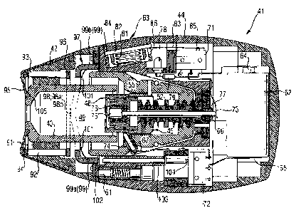
Figure 4 shows a cross section of application device 41
including the housing components. As well as containing the
functional components, the housing has important functions
of its own. The nose section 42 of the housing is rigidly
connected to the shell 43 of pressure chamber 49, and serves
l0 as one handle through which the user applies opening and
closing torque. The base section 44 of the housing is
rigidly connected to clamp screw 52, and serves as the other
handle. The base section 44 of the housing rotates relative
to the receiver ring 55 and breechblock 45. In combination,
the nose section 42 and the base section 44 of the housing
also act as visual and tactile indicators, since they have
oval profiles that line up when the device is fully closed.
Closure of application device 41 is assisted by a spring-
loaded pin and detent 61 that latch the application device
41 in the closed position. Additional functions and features
of the housing will become evident in the descriptions of
other aspects of application device 41.
Figures 5 to 9 show various views of the nose section 42 and
of some of its components. Fig. 5 shows a side view of the
nose section 42 of an application device of the kind shown
by Fig. 4. Fig. 6 shows a first perspective view of the nose
section 42 shown by Fig. 5. Fig. 7 shows a second
perspective view of the nose section 42 shown by Fig. 5.
Fig. 8 shows a first exploded view of components of the nose
section 42 shown by Figures 5-7. Fig. 9 shows a second
exploded view of components of the nose section 42 shown by
Figures 5-7.
Electric Ignition Syatam
CA 02372319 2002-02-19
- 23 -
Figures 10 and 11 show schematic representations of the
electric ignition system of application device 41.
In its simplest form, the electric ignition system of
application device 41 consists of a battery 62, an actuation
switch 63 controlled by the user, electrical contacts that
engage electrical contacts of cartridge 11, and
interconnection conductors. The user loads a fresh cartridge
11 into application device 41, closes and locks this device,
removes break-off protective cap 17, presses jet orifice 18
against the skin at the injection site, and then presses
push button 63 of the actuation switch. Current passing
through an electrically heated wire in the gas generator of
cartridge 11 lights the propellant and starts the injection.
The invention uses this basic approach, and adds interlock
mechanisms to reduce the chance of premature actuation that
could cause a hazard or waste an injection cartridge.
The physical configuration of the electric ignition system
of this invention is illustrated in Fig. 4. Except as noted,
the ignition components are attached to the base section 44
of the housing. Battery 62 is permanently connected by
soldering or a similar means, and will normally last the
life of application device 41. The positive battery terminal
64 is electrically connected to the input terminal of the
normally open actuation rnicroswitch 71, and the negative
terminal 65 is connected to the input terminal of the
normally open interlock microswitch 72. The output terminal
of the actuation microswitch 71 is connected to a conductive
spring member 73 that is biased into contact with the
central ignition contact pin 66. This contact connection is
required since the central ignition contact pin 66 rotates
with the receiver ring 55, not with the base section 44 of
the housing. The output terminal of the interlock
CA 02372319 2002-02-19
(T:\VB\H89CHRSI\100531 ~ Prt: ~6.1~.5001 VE?
- 24 -
microswitch 72 is connected to a conductive spring member 67
that is biased into contact with the sliding conductive
transfer pin 74 in the receiver ring 55. The transfer pin 74
forms a conductive path from the conductive spring member 67
to the co-volume setting ring 48 and then to the breechblock
45. Because the base section 44 of the housing and the .
receiver ring 55 have rotational and axial relative motion,
contact takes place and ignition is possible only when clamp
screw 52 is in the predetermined actuation position.
The central ignition contact pin 66 presses against the
cartridge center ignition contact 32. The pin head 75 is
structurally connected to the sliding breechblock 45, but
electrically isolated by an insulating bushing 76. The pin
shaft passes through clearance holes in the breechblock 45
and clamp screw 52, and is supported on center by an
insulating sleeve bearing 77 to maintain electrical
isolation.
The electrically conductive sliding breechblock 45 presses
against the outer ignition contact 31 of cartridge 11. As
described above, current can only flow to the breechblock 45
when the clamp screw 52 is in the actuation position and the
transfer pin 74 makes contact with the conductive spring
member 67.
When the interlock microswitch 72 is closed and the clamp
screw 52 is in the actuation position, the actuation
microswitch 71 is the only remaining barrier to current flow
through the ignition contacts and the electrically heated
wire 35 in cartridge 11. This results in the battery voltage
appearing between the input and outlet terminals of the
actuation microswitch 71. This "ready to actuate" condition
is visually indicated by a LED 78 connected across the
CA 02372319 2002-02-19
- 25 -
terminals. Actuation then takes place when the user closes
the actuation microswitch 71 by pressing push button 63.
A mechanism consisting of a pushbutton 63, coil spring 81,
pin lever 82 and flat spring 83 is used to close the
actuation microswitch 71 when the user presses the push
button 63. This arrangement allows the pushbutton 63 to be
positioned so that it is convenient for the user, while the
actuation microswitch 71 is positioned where housing apace
is available. The pushbutton 63 slides in a sleeve 84 in the
housing, and is biased out by the coil spring 81. The pin
lever 82 serves a dual purpose. First, it is pressed into
the pushbutton 63 and extends into openings in the sides of
the sleeve 84 to retain the pushbutton 63 in the housing.
Second, it acts as a lever that transfers the pushbutton
motion to the flat spring 83 that engages the actuation
microswitch operating plunger 85. The pin lever 82 pivots in
a hole in the side of the sleeve 84 nearest the nose section
42 of the housing of the application device 41, and swings
through a slot 86 in the opposite side. The flat spring 83
is anchored at one end, and passes over the microswitch 71
and extends to engage the end of the pin lever 82. When the
pin lever 82 swings, it deflects the flat spring 83 towards
the actuation microswitch 71 and pushes the actuation
plunger 85. The sleeve 84 in the housing is made of
translucent plastic that is illuminated by the "ready to
actuate" LED 78.
The schematic representation of the electrical ignition
system shown by Fig. 10 illustrates the fact that in order
that an injection can be performed with application device
41 the following switches have to be closed: switches 71,
72, and switch formed by lock mechanism 51, spring-loaded
pin and detent 61 and electrical conductive transfer pin 74.
This latter switch is only then closed when the application
CA 02372319 2002-02-19
- 26 -
device 41 is completely assembled, that is when the
components contained in nose section 42, in base section 44,
and the cartridge 11 are all in the proper position with
respect to each other:
The schematic representation of the electrical ignition
system shown by Fig. 11 illustrates the state of this system
when the application device 41 is completely assembled and
all necessary contacts for the ignition are established with
exception of switches 71 and 72 which are still open. In
this state LED 78 received a current limited by resistor 79.
This current is well below the value necessary to cause
ignition by electrically heating ignition wire 35, but is
large enough to cause light emission by LED 78 and thereby
signalize that application device 41 would become ready for
performing an injection if and when properly positioned on
the injection site.
When the application device 41 reaches a proper position on
the injection site, switch 72 is closed by this positioning,
and actuation of push button 63 by the user can then cause
closure of switch 71. If this happens, the electrical
ignition circuit is closed and a sufficiently large current
is fed to ignition wire 35 to cause ignition of the
propellant in cartridge 11.
Obj~ct Sensor / Position detector
The object sensor or position detector requires the nose
section 42 of the housing of the application device 41 to be
pressed uniformly against the skin surface at the injection
site before actuation is possible/allowed. The object sensor
/ position detector is illustrated in Figure 4. The nose
section 42 of the housing includes a flat annular surface 91
CA 02372319 2002-02-19
- 27 -
which surrounds the end of the shell 43 of pressure chamber
49 that protrudes from the housing and the injection nozzle.
A pair of diametrically opposed sensor pins 92, 93 slide in
holes in the housing, and their ends extend a short distance
above the surface in the rest position. The interlock system
according to the invention requires that both sensor pins
92, 93 are pushed flush with the annular surface 91 to
enable execution of an injection. Sensor pins 92, 93 support
a concentric rigid metal sensor ring 94 that is free to
pivot at the contact points with the sensor pins 92, 93.
This defines the condition that two or more separate points
must be pressed to push the sensor ring 94 and both pins 92,
93 flush with the annular surface 91 and enable execution of
an injection. If the sensor ring 94 is pressed at any one
point around its circumference it will tip, and at most one
of the two sensor pins 92, 93 will be pushed flush with the
annular surface 91. The annular area, including the sensor
ring 94 and sensor pins 92, 93, is covered by a flexible
rubber boot 95. The inner edge of the boot 95 is bonded to
the shell 43 of the pressure chamber 49 at a bond point 105,
and the outer edge of boot 95 fits in a groove in the nose
section 42 of the housing. The boot 95 forms a smooth,
easily cleaned surface and protects the mechanism. It also
retains the sensor ring 94 and holds it in the proper
spatial relationship with the sensor pins 92, 93 at the rest
position.
The sensor pins 92, 93 push a relay ring f6 inside the nose
section 42 of the housing. The relay ring 96 in turn pushes
a tilt plate 97. The tilt plate 97 contacts the relay ring
96 with two diametrically opposed raised pivot points 98
(98a respectively 98b), and two diametrically opposed legs
99 (99a respectively 99b) extend towards the base section 44
of the housing. The legs 99 are offset 90 degrees from the
pivot points 98, and lie in the same plane as the sensor
CA 02372319 2002-02-19
- 28 -
pins 92, 93. A return spring 101 formed from sheet spring
material pushes the tilt plate 97, relay ring 96 and sensor
pins 92, 93 towards the nose section 42 of the housing so
that the sensor ring 94 is pushed out to the rest position.
A cover plate 1.02 on the surface of the nose section 42 of
the housing that abuts the base section 44 of the housing
supports the return spring 101 and shields the mechanism.
The tilt plate legs 99 pass through holes in the cover plate
102, with their ends flush with the outer surface in the
rest position.
When the nose section 42 of the housing is attached to the
base section 44 of the housing and the clamp screw 52 is
locked, one of the two tilt plate legs 99 is aligned with
the interlock push pin 103. This pin contacts the interlock
microswitch plunger 104, and closes the interlock
microswitch 72 when it is pushed by one of the tilt plate
legs 99. The other tilt plate leg contacts the base section
44 of the housing and forms a pivot point. If the sensor
ring 94 pushes both sensor pins fully, then the relay ring
96 is pushed uniformly against the two tilt plate pivot
points. This causes the tilt plate 97 to rotate around the
pivot point formed by the leg in contact with the housing so
that the other leg extends, pushes the interlock push pin
103, and closes the interlock microswitch 72. In the event
that only one sensor pin 92 or 93 is pushed, the relay ring
96 tilts rather than moving uniformly. The two points on the
relay ring 96 that contact the tilt plate 97 pivots move
only half the full distance, with the result that the tilt
plate leg 99 moves only half the full distance and does not
close the interlock switch 72.
This above described object sensor/position detector has a
number of useful features. First, it is electromechanical,
and does not contain any electronic devices that are
CA 02372319 2002-02-19
- 29 -
sensitive to and whose operation can be affected by spurious
signals from electrostatic discharge or other sources of
electromagnetic interference. Second, the electric ignition
circuit is totally within the base section 44 of the
housing, with no connections to the removable nose section
42 of the housing that could compromise reliability. Third,
additional safety is provided by the fact that the device
must be fully closed and locked to align the tilt plate leg
99 with the interlock push pin 103. Fourth, the structure of
the object sensor/position detector is symmetrical, so that
the nose section 42 of the housing may be connected to the
base section 44 of the housing in either of two positions
which are angularly spaced from each other of 180 degrees.
List of reference numbers
11 medication cartridge / cartridge assembly
12 cartridge shell
13 nozzle body
14 flexible container wall
15 medication reservoir
16 liquid medication
17 break-off protective cap
18 jet orifice
19
20
21 envelope
22 fluid channel
23 gas generator body
24 propellant chamber
25 outlet orifice plate
26 closure plug / closure plate
27 gas pressure chamber
28 annular co-volume
CA 02372319 2002-02-19
- 30 -
29
31 ignition contact
32 ignition contact
5 33 internal support
34 co-volume seal ring
electrically heated wire /ignition wire
36
37
10 38
39
41 application device
42 nose section
15 43 shell of pressure chamber
44 base section
breech block
46 reduced diameter opening
47 full diameter opening
20 48 co-volume setting ring
49 pressure chamber
51 lock mechanism
52 clamp screw
25 53 male locking lugs
54 female pockets
receiver ring
56 interlock lever
57 interlock lever
30 58 cam groove
59 cam groove
bias spring
61 spring-loaded pin and detent
62 battery
35 63 push button / actuation button
CA 02372319 2002-02-19
- 31 -
64 positive terminal
65 negative terminal
66 central ignition contact pin
67 conductive spring member
68 arm portion
69 latch portion
70 pivot
71 actuation micro-switch
72 interlock micro-switch
73 electrical conductive spring member
74 electrical conductive transfer pin
75 pin head
76 insulating bushing
77 insulating sleeve bearing
78 Light Emitting Diode (LED)
79 electrical resistance
80
81 coil spring
82 pin lever
83 flat spring
84 sleeve
85 operating plunger /actuation plunger
86 slot
8?
88
89
90
91 flat annular surface
92 sensor pin
93 sensor pin
94 metal sensor ring
95 flexible rubber boot
96 relay ring
97 tilt plate
98 pivot point (98a, 98b)
CA 02372319 2002-02-19
- 32 -
99 leg (99a, 99b)
100
. 101 return spring
102 cover plate
103 interlock push pin
104 interlock microswitch plunger
105 bond point
Although a preferred embodiment of the invention has been
described using specific terms, such description is for
illustrative purposes only, and it is to be understood that
changes and variations may be made without departing from
the spirit or scope of the following claims.
- - - - -