Sélection de la langue

Search

Sommaire du brevet 2372373 

Énoncé de désistement de responsabilité concernant l'information provenant de tiers

Une partie des informations de ce site Web a été fournie par des sources externes. Le gouvernement du Canada n'assume aucune responsabilité concernant la précision, l'actualité ou la fiabilité des informations fournies par les sources externes. Les utilisateurs qui désirent employer cette information devraient consulter directement la source des informations. Le contenu fourni par les sources externes n'est pas assujetti aux exigences sur les langues officielles, la protection des renseignements personnels et l'accessibilité.

Disponibilité de l'Abrégé et des Revendications

L'apparition de différences dans le texte et l'image des Revendications et de l'Abrégé dépend du moment auquel le document est publié. Les textes des Revendications et de l'Abrégé sont affichés :

  • lorsque la demande peut être examinée par le public;
  • lorsque le brevet est émis (délivrance).
(12) Brevet: (11) CA 2372373
(54) Titre français: INSTALLATION DE TRANSPORT DE PERSONNES D'UNE STATION PLUS ELEVEE A UNE STATION MOINS ELEVEE
(54) Titre anglais: INSTALLATION FOR CARRYING PERSONS FROM A HIGHER STATION TOWARDS A LOWER STATION
Statut: Périmé et au-delà du délai pour l’annulation
Données bibliographiques
(51) Classification internationale des brevets (CIB):
  • B61B 03/00 (2006.01)
  • A63G 21/04 (2006.01)
  • B61B 07/00 (2006.01)
  • B61B 12/02 (2006.01)
  • E01B 25/18 (2006.01)
  • E01B 25/24 (2006.01)
(72) Inventeurs :
  • ALBRICH, REINHARD (Autriche)
(73) Titulaires :
  • INNOVA PATENT GMBH
(71) Demandeurs :
  • INNOVA PATENT GMBH (Autriche)
(74) Agent: SMART & BIGGAR LP
(74) Co-agent:
(45) Délivré: 2007-11-13
(22) Date de dépôt: 2002-02-20
(41) Mise à la disponibilité du public: 2002-09-07
Requête d'examen: 2005-09-30
Licence disponible: S.O.
Cédé au domaine public: S.O.
(25) Langue des documents déposés: Anglais

Traité de coopération en matière de brevets (PCT): Non

(30) Données de priorité de la demande:
Numéro de la demande Pays / territoire Date
A 357/2001 (Autriche) 2001-03-07

Abrégés

Abrégé anglais


Persons can be carried downhill from a mountain station to a
valley station. A guide rail is fastened on a supporting cable
at a distance above the ground. The guide rail is formed of a
multiplicity of sub-rails and carriages with a chair, a cabin,
or the like can be displaced along the rail. The sub-rails are
connected to one another such that they can be displaced in
the longitudinal direction of the guide rail.

Revendications

Note : Les revendications sont présentées dans la langue officielle dans laquelle elles ont été soumises.


I Claim:
1. An installation for downhill transportation of persons
from a higher station to a lower station, comprising:
a guide rail extending between the higher station and the
lower station and along which carriages are displaceable;
a supporting cable fastening said guide rail at a distance
above ground;
said guide rail being formed of a multiplicity of sub-rails
connected to one another and displaceable relative to one
another in a longitudinal direction of the guide rail.
2. The installation according to claim 1, wherein said sub-
rails are tubular elements with ends and an interior, said
ends are each formed with at least one crosspiece passing
through said interior, one of said crosspieces is formed with
an elongated hole and the crosspieces overlap one another, and
wherein at least one screw connects said crosspieces between
two respective said sub-rails.
3. The installation according to claim 2, wherein each said
sub-rail has a first crosspiece at one end thereof, formed
with an elongated hole, and two further crosspieces at another
end thereof, said two further crosspieces butting against said
-10-

first crosspiece on both sides when two sub-rails are
connected to one another and said screw passing through said
elongated.
4. The installation according to claim 1, which comprises
supporting brackets fastening said sub-rails on said
supporting cable, said supporting brackets being displaceably
attached to said supporting cable.
5. The installation according to claim 1, wherein said sub-
rails are formed, on an outer side thereof, with at least one
projecting bar for running support of guide rollers arranged
on the carriage.
6. The installation according to claim 5, which comprises at
least one further bar projecting from said sub-rails, said
further bar forming one of two interacting elements of an
electromagnetic braking assembly.
7. The installation according to claim 6, wherein said at
least one guide bar and said at least one braking bar project
substantially diametrically from said sub-rails.
8. The installation according to claim 1, wherein said sub-
rails are formed with running surfaces for supporting running
rollers and for guide rollers of the carriages running along
-11-

said guide rail in a running direction, and wherein said
joints run in a step-like manner relative to the running
direction.
9. The installation according to claim 1, wherein said sub-
rails are formed with running surfaces for supporting running
rollers and for guide rollers cf the carriages running along
said guide rail in a running direction, and wherein said
joints are oriented obliquely relative to the running
direction.
10. The installation according to claim 1, wherein said sub-
rails have mutually assigned end surfaces formed with mating
components welded onto respective ends of said sub-rails.
-12-

Description

Note : Les descriptions sont présentées dans la langue officielle dans laquelle elles ont été soumises.

CA 02372373 2002-02-20
WRA-33199
INSTALLATION FOR CARRYING PERSONS FROM
A HIGHER STATION TOWARDS A LOWER STATION
Background of the Invention:
Field of the Invention:
The present invention relates to an installation for carrying
individuals down from a higher station (a mountain station)
i0 towards a lo-v:er station (a valley station) . The installation
has a guide rail which is fastened on a supporting cable at a
distance above the ground. The guide rail comprises a
multiplicity of sub-rails. Carriages with a chair, a cabin, or
the like can be displaced along the guide rail.
is
A system of that type is described in my earlier specification
us
application No. 09/488,741, published as European application
EP 1 026 061 A2. There, the guide rail comprises a
multiplicity of sub-rails which are connected rigidly to one
20 another and are fastened on a supporting cable by means of
brackets. Since, in the case of a rigid guide rail, those
locations at which the carriages are located are subjected to
very high loading in each case, the sub-rails and the
connections thereof have to be of very large dimensions. In
25 addition, such rails are also subjected to high levels of
-1-

CA 02372373 2002-02-20
stressing, and resulting loading, on account of the heat
expansion.
Summary of the Invention:
it is accordi;:gly an object of the invention to provide an
installation for the downhill transportation of persons from a
higher station to a lower station, which overcomes the above-
mentioned disadvantages of the heretofore-known devices and
methods of this general type and which reduces the loading to
which the guide rail is subjected, for which reason the guide
rail may be of smaller dimensions.
with the foregoing and other objects in view there is
provided, in accordance with the invention, an installation
for downhill transportation of persons from a higher station
to a lower station, comprising:
a guide rail extending between the higher station and the
lower station and aleng which carriages are displaceable;
a supporting cable fastening the guide rail at a distance
above ground;
the guide rail being formed of a multiplicity of sub-rails
connected to or.e another and displaceable relative to one
another ir, a longitudinal direction of the guide rail.
-2-

CA 02372373 2002-02-20
In other words, the objects of the invention are achieved in
that the sub-rails are connected to one another such that they
can be displaced in the longitudinal direction of the guide
rail.
The sub-rails, i.e., the rail sections, are preferably
designed as tubular elements which are designed in their
interior, at their ends, with in each case at least one
crosspiece passing through the interior, one of the
crosspieces being provided with a slot and the crosspieces
overlapping one another, it being the case that at least one
screw which connects the crosspieces is provided between two
sub-rails. According to a preferred embodiment, each sub-rail
is designed, at one end, with a first crosspiece which is
provided with a slot, and is designed, at its other end, with
two further cresspieces, on which a screw is fastened, the two
further crosspieces butting against the first crosspiece on
both sides and the screw passing through the slot.
Furthermore, the sub-rails are preferably fastened on the
supporting cable by means of supporting brackets, it being
possible for these to be displaced in relation to the
supporting cable.
In accordance with an additional feature of the inventien, the
sub-rails are designed, on their outer sides, with at least
one projecting bar along which guide rollers arranged on the
-3-

CA 02372373 2002-02-20
carriage run, and projecting from the sub-rails is at least
one further bar, which forms one of the two interacting
elements ol an electromagnetic braking arrangement. In this
case, the az least one guide bar and the at least one braking
bar may project more or less diametrically f'rom the sub-rails.
Other features which are considered as characteristic for the
invention are set forth in the appended claims.
Although the invention is illustrated and described herein as
embodied in an installation for carrying individuals down from
a mountain station into a valley station, it is nevertheless
not intended to be limited to the details shown, since various
modifications and structural changes may be made therein
without departing from the spirit of the invention and within
the scepe and range of equivalents o~ the claims.
The construction and method of operation of the invention,
however, together with additional objects and advantages
thereof will be best understood from the following description
of specific e:-~bodiments when read in connection with the
accompanying drawings.
Brief Description of the Drawinqs:
Fig. 1 is a schematic plan view of an installation according
to the invention;
-4-

CA 02372373 2002-02-20
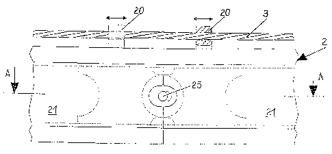
Fig. 2 is a partial side view illustrating the connection of
two subrails in a first operating position;
Fig. 2a is a section taken along the line A-A in Fig. 2,
illustrating the connection of the sub-rails in the first
operating position;
Fig. 3 is a partial side view illustrating the connection of
the two sub-rails in a second operating position;
Fig. 3a is a section taken along the line B-B in Fig. 3,
illustrating the connection of the sub-rails in the second
operating position;
Fig. 4 is a cross-sectional view through two sub-rails in the
region of their connection;
Fig. 5 is a side view of the end surfaces of two sub-rails;
and
Fig. 5a is a plan view onto the end surfaces of the two sub-
rails.
-5-

CA 02372373 2002-02-20
Description of the Preferred Embodiments:
Referring now to the figures of the drawing in detail and
first, particularly, to Fig. 1 thereof, there is shown an
installation according to the inventien with a higher station
1 (also referred to as a mountain station 1) and a lower
station 1a (also referred to as a valley station la), between
which a guide rail 2 extending from the mountain station 1 to
the valley station la is located. The guide rail 2 has
rectilinear segments 2a and curved segments 2b. Fastened on
supports, columns and the like are supporting cables 3, on
which the guide rail 2 is fastened at a distance above the
ground. Carriages 4, on which chairs, suspension gear, cabins
or the like are fastened, can be displaced along the guide
rail 2 from the mountain station 1 towards the valley station
la.
With reference to Figs. 2 and 2a, the guide rail 2 comprises a
multiplicity of sub-rails 21, which are fastened on the cable
3 by means of supporting brackets 20. The sub-rails 21, which,
by way of for example, are of hollow-cylindrical design, are
designed in the interior, at one end, with a more or less
diagonally running crosspiece 22, which projects beyond the
surface of the sub-rails 21 and which is formed with an
elongated hole or slot 22a. At their other end, they are
designed with two diagonally running crosspieces 23 and 24,
which likewise project beyond the end surface of the sub-rails
-6-

CA 02372373 2002-02-20
21 and on which there is fastened at least one bolt 25, which
passes through the slot 22a. The sub-rails 21 are connected to
one another by means of the crosspieces 22, 23 and 24 and the
bolts 25, it :,eing possible for the sub-rails to be displaced
in relation to one another by the length of the slot 22a.
Since the supporting brackets 20 can be displaced in the
longitudinal direction on the cable 3, this allows the sub-
rails 21 to move in relation to one another in the
longitudinal direction of the guide rail 2 in dependence on
the loading to which they are subjected.
Figs. 2 and 2a illustrate the position of the guide rail 2 in
the non-loaded state. In this case, the ends of the sub-rails
21 butt against one another. In contrast, Figs. 3 and 3a
illustrate the sub-rails 21 in the position they assume when a
carriage 4 is located in the region thereof. The resulting
loading causes the guide rail 2 to bend, as a result of which
the sub-rails 21 move apart from one another to the extent
which is determined by the length of the slot 22a. Since the
tensile forces acting on the guide rail 2 are thus reduced to
a considerable extent, it is possible for the sub-rails 21 and
the crosspieces 22, 23 and 24 connecting the same to be of far
smaller dimensions than if the sub-rails 21 were connected
rigidly to one another. In addition, the guide rail 2 can
expand as a result of heat.
-7-

CA 02372373 2002-02-20
with reference to Fig. 4, supporting rollers 41 of the
carriages 4 run on the surface of the sub-rails 21.
Furthermore, the sub-rails 21 are designed, both on their top
side and on their underside, =aith radially projecting
continuations 56 which form abutment surfaces for guide
rollers 42 or the carriages 4. Also projecting from the bottom
continuation 56 are bars 57 which form constituent parts of an
electromagnetic braking assembly. Additional information with
regard to the electromagnetic braking assembly may be found in
my copendir.g patent application [Attorney Docket No. WRA-
331273 , the disclosure of which is herewith incorporated by
reference.
Figs. 5 and 5a, furthermore, illustrate the configuration of
the end surfaces of the sub-rai?s 21. As can be seen from Fig.
5, the continuations 56 are designed, in the longitudinal
direction of the sub-rails 21, with mating bevels 56a and 56b.
This ensures that the running surfaces for the guide rollers
42 are designed with a joint which runs obliquely in relation
to the running direction, as a result of which the necessary
smooth running of the guide rollers 42 is ensured.
Ar:alogously, the lateral surfaces of the sub-rails 21 are also
designed, in the regions of the running surfaces for the
supporting rollers 41, with mating protrusions 27, which are
oriented in the running direction, and with mating recesses 28
-8-

CA 02372373 2002-02-20
assigned to said protrusions, as a result of which smooth
rolling of the supporting rollers 41 is likewise ensured.
The mutually -assigned end surfaces of the sub-rails 21 are
advantageouslv designed as annular, mating components 26 which
are welded onto the end sides of the sub-rails 21.
-9-

Dessin représentatif
Une figure unique qui représente un dessin illustrant l'invention.
États administratifs

2024-08-01 : Dans le cadre de la transition vers les Brevets de nouvelle génération (BNG), la base de données sur les brevets canadiens (BDBC) contient désormais un Historique d'événement plus détaillé, qui reproduit le Journal des événements de notre nouvelle solution interne.

Veuillez noter que les événements débutant par « Inactive : » se réfèrent à des événements qui ne sont plus utilisés dans notre nouvelle solution interne.

Pour une meilleure compréhension de l'état de la demande ou brevet qui figure sur cette page, la rubrique Mise en garde , et les descriptions de Brevet , Historique d'événement , Taxes périodiques et Historique des paiements devraient être consultées.

Historique d'événement

Description Date
Le délai pour l'annulation est expiré 2009-02-20
Lettre envoyée 2008-02-20
Accordé par délivrance 2007-11-13
Inactive : Page couverture publiée 2007-11-12
Inactive : Taxe finale reçue 2007-08-23
Préoctroi 2007-08-23
Un avis d'acceptation est envoyé 2007-07-09
Lettre envoyée 2007-07-09
Un avis d'acceptation est envoyé 2007-07-09
Inactive : Approuvée aux fins d'acceptation (AFA) 2007-05-28
Inactive : CIB de MCD 2006-03-12
Lettre envoyée 2005-10-14
Exigences pour une requête d'examen - jugée conforme 2005-09-30
Toutes les exigences pour l'examen - jugée conforme 2005-09-30
Requête d'examen reçue 2005-09-30
Demande publiée (accessible au public) 2002-09-07
Inactive : Page couverture publiée 2002-09-06
Inactive : CIB attribuée 2002-05-08
Inactive : CIB en 1re position 2002-05-08
Lettre envoyée 2002-03-19
Inactive : Certificat de dépôt - Sans RE (Anglais) 2002-03-19
Demande reçue - nationale ordinaire 2002-03-18

Historique d'abandonnement

Il n'y a pas d'historique d'abandonnement

Taxes périodiques

Le dernier paiement a été reçu le 2007-02-19

Avis : Si le paiement en totalité n'a pas été reçu au plus tard à la date indiquée, une taxe supplémentaire peut être imposée, soit une des taxes suivantes :

  • taxe de rétablissement ;
  • taxe pour paiement en souffrance ; ou
  • taxe additionnelle pour le renversement d'une péremption réputée.

Les taxes sur les brevets sont ajustées au 1er janvier de chaque année. Les montants ci-dessus sont les montants actuels s'ils sont reçus au plus tard le 31 décembre de l'année en cours.
Veuillez vous référer à la page web des taxes sur les brevets de l'OPIC pour voir tous les montants actuels des taxes.

Historique des taxes

Type de taxes Anniversaire Échéance Date payée
Taxe pour le dépôt - générale 2002-02-20
Enregistrement d'un document 2002-02-20
TM (demande, 2e anniv.) - générale 02 2004-02-20 2004-01-20
TM (demande, 3e anniv.) - générale 03 2005-02-21 2005-01-24
Requête d'examen - générale 2005-09-30
TM (demande, 4e anniv.) - générale 04 2006-02-20 2006-01-23
TM (demande, 5e anniv.) - générale 05 2007-02-20 2007-02-19
Taxe finale - générale 2007-08-23
Titulaires au dossier

Les titulaires actuels et antérieures au dossier sont affichés en ordre alphabétique.

Titulaires actuels au dossier
INNOVA PATENT GMBH
Titulaires antérieures au dossier
REINHARD ALBRICH
Les propriétaires antérieurs qui ne figurent pas dans la liste des « Propriétaires au dossier » apparaîtront dans d'autres documents au dossier.
Documents

Pour visionner les fichiers sélectionnés, entrer le code reCAPTCHA :


Pour visualiser une image, cliquer sur un lien dans la colonne description du document (Temporairement non-disponible). Pour télécharger l'image (les images), cliquer l'une ou plusieurs cases à cocher dans la première colonne et ensuite cliquer sur le bouton "Télécharger sélection en format PDF (archive Zip)" ou le bouton "Télécharger sélection (en un fichier PDF fusionné)".

Liste des documents de brevet publiés et non publiés sur la BDBC .

Si vous avez des difficultés à accéder au contenu, veuillez communiquer avec le Centre de services à la clientèle au 1-866-997-1936, ou envoyer un courriel au Centre de service à la clientèle de l'OPIC.

({010=Tous les documents, 020=Au moment du dépôt, 030=Au moment de la mise à la disponibilité du public, 040=À la délivrance, 050=Examen, 060=Correspondance reçue, 070=Divers, 080=Correspondance envoyée, 090=Paiement})


Description du
Document 
Date
(aaaa-mm-jj) 
Nombre de pages   Taille de l'image (Ko) 
Dessin représentatif 2002-05-16 1 9
Abrégé 2002-02-19 1 14
Description 2002-02-19 9 267
Revendications 2002-02-19 3 81
Dessins 2002-02-19 3 81
Dessin représentatif 2007-10-15 1 9
Courtoisie - Certificat d'enregistrement (document(s) connexe(s)) 2002-03-18 1 113
Certificat de dépôt (anglais) 2002-03-18 1 164
Rappel de taxe de maintien due 2003-10-20 1 106
Accusé de réception de la requête d'examen 2005-10-13 1 176
Avis du commissaire - Demande jugée acceptable 2007-07-08 1 165
Avis concernant la taxe de maintien 2008-04-01 1 172
Taxes 2004-01-19 1 34
Taxes 2005-01-23 1 27
Taxes 2006-01-22 1 28
Taxes 2007-02-18 1 29
Correspondance 2007-08-22 1 27