Sélection de la langue

Search

Sommaire du brevet 2373181 

Énoncé de désistement de responsabilité concernant l'information provenant de tiers

Une partie des informations de ce site Web a été fournie par des sources externes. Le gouvernement du Canada n'assume aucune responsabilité concernant la précision, l'actualité ou la fiabilité des informations fournies par les sources externes. Les utilisateurs qui désirent employer cette information devraient consulter directement la source des informations. Le contenu fourni par les sources externes n'est pas assujetti aux exigences sur les langues officielles, la protection des renseignements personnels et l'accessibilité.

Disponibilité de l'Abrégé et des Revendications

L'apparition de différences dans le texte et l'image des Revendications et de l'Abrégé dépend du moment auquel le document est publié. Les textes des Revendications et de l'Abrégé sont affichés :

  • lorsque la demande peut être examinée par le public;
  • lorsque le brevet est émis (délivrance).
(12) Brevet: (11) CA 2373181
(54) Titre français: PANNEAU CONSTITUE D'UNE TOILE ELECTROTHERMIQUE A FORTE ISOLATION
(54) Titre anglais: PANEL MADE OF A HIGHLY INSULATED ELECTROTHERMAL FABRIC
Statut: Périmé et au-delà du délai pour l’annulation
Données bibliographiques
Abrégés

Abrégé français

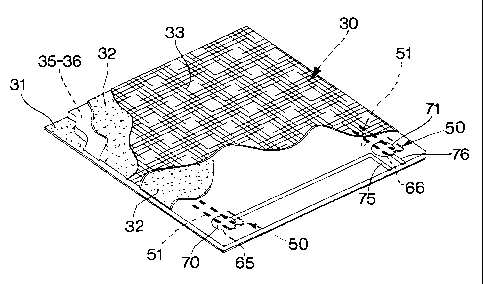
L'invention concerne une structure (10) conçue pour générer et diffuser de la chaleur obtenue d'un panneau (30) constitué d'au moins une pièce de toile électrothermique, des bandes de fibres de verre étant disposées côte à côte de façon à former la chaîne. La trame (50) est constituée d'un long fil de cuivre continu (51) au diamètre réduit, revêtu d'une matière isolante, qui s'étend en ligne sinueuse alternativement au-dessus et au-dessous des bandes de fibres de verre. Le panneau (30) est complété de couches intermédiaire et externe (35, 36) d'une matière époxyde thermoadhésive, les deux surfaces du panneau étant recouvertes de feuilles de micanite (31, 32), de façon qu'en reliant les extrémités du fil (51) formant la trame (50) à une source électrique, et en perçant des orifices (65, 66), au moyen d'un faisceau laser par exemple, dans les couches thermoadhésives (35, 36) recouvrant la trame (50), cette dernière transforme l'énergie électrique en énergie thermique.


Abrégé anglais


Panel (10) for generating and diffusing heat obtained from a heat-radiating
board (30) comprising one or more pieces of electrothermal
fabric with strips of fibreglass laid side by side to form the warp, the weft
(50) consisting of a continuous copper wire (51), small in diameter
and of considerable length, coated with insulating material, that extends
serpentinewise passing alternatively above and below the strips of
fibreglass, said board (30) being completed by intermediate and external
layers (35, 36) of epoxidic thermoadhesive material and clad on
both surfaces with sheets of micanite (31, 32), so that on connecting the ends
of the wire (51) forming the weft (50) to a source of electric
current, boring holes (65, 66) using means, that may be a laser beam, on the
thermoadhesive layer (35, 36) covering the weft (50), this
latter converts electric energy into thermal energy.

Revendications

Note : Les revendications sont présentées dans la langue officielle dans laquelle elles ont été soumises.


9
CLAIMS
1. A panel made with electrothermal fabric for generating and diffusing
heat,
wherein the panel comprises a heat-radiating board comprising at least one
piece of electrothermal fabric, said fabric comprising a warp weave of
parallel
strips laid side by side and a weft weave of continuous highly conductive wire
coated with insulating material and having ends provided with electrical
contacts, said board further comprising intermediate and external layers of
thermal adhesive material and being covered on front and rear surfaces by
external sheets of mica-based material so that in connecting the contacts to a
source of electric current, the wire forming the weft weave converts electric
energy into thermal energy and diffuses heat into the environment by radiation
through the external sheets of mica-based material.
2. The panel of claim 1, wherein the strips of warp weave of the pieces of
electrothermal fabric comprise thin threads of fibreglass laid side by side.
3. The panel of claim 1 or 2 wherein the wire comprising the weft weave
extends continuously from a first corner on a first side of at least one piece
of
fabric, crosswise to the warp strips passing alternately over a first face of
the
first strip, over a second face of the next strip, over the first face of the
strip
next again and so on to reach the opposite side of the piece and from there,
after making a bend of 180°, said wire returns towards the first side
closely
aligned along the whole of the previously inserted length and, from this first
side, said wire makes a bend of 180° and returns towards the opposite
side of
the piece passing over the second face of the first strip, over the first face
of
the next strip, over the second face of the strip next again and so on, to
complete the whole weft of the piece, the effect of aligning the lengths of
conducting wire through which the electric current passes in the opposite
direction of flow being to eliminate electric fields.

10
4. The panel of any one of claims 1 to 3, wherein the highly conductive
wire of the weft weave is copper wire.
5. The panel of any one of claims 1 to 4, wherein the electrical contacts
are joined at the two ends of the wire that comprise the weft and that are to
be
used for transforming electric current into thermal energy, a hole being made
by suitable means in the thermoadhesive layer which covers one or both
surfaces of the electrothermal board, said hole also comprising the insulating
coating on the wire, a weld being made in said hole to connect said wire to an
electrical contact.
6. The panel of claim 5, wherein the hole is made by a grinder.
7. The panel of claim 5, wherein the hole is made by sanding.
8. The panel of claim 5, wherein the hole is made by a laser beam, the
nature of which causes it to penetrate the insulating coating on the wire
forming the weft but to be repelled by the metal of the wire.
9. The panel of any one of claims 1 to 8, wherein the heat-radiating board
is mounted inside a protective frame.
10. The panel of claim 9, wherein the frame is made of two opposing
halves of a constant section in accordance with an angle of 90°, having
internal shapes and dimensions corresponding to the external shapes and
dimensions of the internal parts of the panel and being provided with means
for stable assembly.
11. The panel of claim 10, wherein the external dimensions of one half of
the frame correspond to the internal dimensions of the other half.

11
12. The panel of any one of claims 1 to 11, wherein the panel is square in
shape.
13. The panel of any one of claims 1 to 12, wherein the external sheets are
of micanite.
14. The panel of claim 13, wherein the micanite comprises flakes of mica
glued onto paper or cloth.
15. The panel of any one of claims 1 to 12, wherein the external sheets are
of micarta.
16. The panel of claim 15, wherein the micarta is applied to a base of
fibreglass.
17. The panel of claim 15, wherein the micarta is impregnated with
polyester or expoxy resins.
18. The panel of any one of claims 1 to 17, wherein a thermal sensor is
placed in a central position on the heat-radiating board, the ends of said
sensor being joined to the two ends of an interruption in the continuous wire
that forms the weft weave, said sensor breaking the electric circuit of the
heat-
radiating board when its temperature rises above a certain level.
19. The panel of any one of claims 1 to 18, wherein the wire which
comprises the weft weave is continuous over substantially two halves of at
least one piece of fabric, the ends of the copper wire that correspond to said
two halves being connected to a thermoelectric sensor that automatically
turns electric current off in that half of the piece wherein the pre-set
temperature level has been exceeded.

12
20. The panel of any one claims 1 to 19, wherein the heat-radiating board
comprises two superimposed pieces of electrothermal fabric with
thermoadhesive layers therebetween and at the ends thereof.
21. The panel of claim 20, wherein the wires forming the weft weave of the
two
superimposed pieces of fabric are connected in parallel.
22. The panel of claim 20, wherein the wires forming the weft weave of the
two superimposed pieces of fabric are connected in series.
23. The panel of claim 1 or 20, wherein the thermoadhesive material is
epoxidic.
24. The panel of any one of claims 1 to 23, wherein the front surface of the
head-radiating board is covered with a sheet of decorative melamine.

Description

Note : Les descriptions sont présentées dans la langue officielle dans laquelle elles ont été soumises.


CA 02373181 2001-11-13
WO 00/70270 PCT/IT99/00193
1 o Panel made of a highly insulated electrothermal fabric
The invention concerns means for generating heat for indoor use by
electric current.
There are innumerable systems and means for generating heat for
this purpose by electricity.
These systems are based on the use of highly resistent materials
which, if electric current is passed through them, reach very high
temperatures at a great concentration of heat.
Such heat is nearly always much more than the environment would
require and must therefore be diffused by means of complex and
2o costly devices specially made for the purpose.
The high temperatures in the heat conductors render necessary
certain means of support made of special and fragile mterials such
as ceramic and the like, and complex insulation and coating
structures
These structures rapidly wear out because of the high temperatures
they have to carry.
Thermal efficiency, especially if compared with other means of
heating by fuels, is very low because of the high thermal difference
between the electric resistances and room temperature
3o The means of heating are also bulky and, from the practical and
aesthetic points of view, are difficult to combine with the furniture.

CA 02373181 2001-11-13
WO 00/70270 2 PCT/IT99/00193
The above invention solves these problems, offering a means of
electric heat that is flat, small in size and light in weight, as well as
being highly insulated, as will be explained below.
Subject of the disclosure is a panel for generation and diffusion of
heat having on it an electrothermal fabric, and a board of heat
radiating material consisting of one or more pieces of said fabric.
Said fabric presents continuous weft wires, coated with highly
insulating material and having electric contacts at their ends.
Intermediate and external layers of thermoadhesive material com-
1 o plete the board, covered on both sides by a mica-based material.
By connecting the electric contacts to a source of electricity, the weft
wires convert electric energy into thermal energy and, through the
sheets of mica-based material, radiate heat throughout the environ-
ment.
The warp threads of the pieces of fabric consist of thin parallel
threads of fibre glass laid side by side.
The weft wires run continuously from a first corner on a first side of
the piece of fabric, crosswise to the weft wires, first passing above a
first face of the first strip, above the second face of the next strip,
2o above the first face of the strip next again, and so on till it reaches
the opposite side of the piece.
From there, after making a bend at 180°, said wire returns to the
first side, closely aligned the whole previously inserted length.
From this first side, after making a another 180° bend, said wire
returns to the opposite side of the piece passing above the second
face of the first strip, above the first face of the next strip, above the
second face of the strip next again, and so on until the whole weft
weave of the piece has been completed.
This way of laying of the conductor in lengths placed side by side,
3o passed through by electric current in the opposite direction of flow,
eliminates the electric fields.

CA 02373181 2001-11-13
WO 00/70270 PCT/IT99/00193
3
Advantageously, the highly conductive weft wire is of copper.
The electric contacts are connected at the two ends of the wire that
forms the weft weave, to be used to convert electric current into
thermal emergy, creating, by suitable means, a hole in the thermo-
adhesive layer that covers one face of the electrothermic sheet.
This hole also passes through the insulation of the wire, a weld, or
equivalent means, being put into said hole to connect said wire to an
electric contact.
The hole may be produced by a grinder, by sanding or by a laser
1 o beam.
Being laser, said beam penetrates the insulating lining on the metal
wire of the weft weave, but is repelled by the metal itself.
The heat radiating plate is mounted inside a protective frame.
This frame consists of two halves, of a constant section at an angle
of 90°, shape and internal dimensions corresponding to the external
dimensions and shape of the main parts of the panel, and being
provided with means for a stable assembly.
The external dimensions of one half of the frame correspond to the
internal dimensions of the other half.
The shape of the panel is preferably square.
The external sheets of the panel are of micanite. This consists of
small flakes of mica glued onto paper or cloth.
In another execution the external sheets are of micarta. The sup-
porting material for micarta is a fabric of fibreglass which can be
impregnated with polyester or epoxy resins.
A thermal sensor is placed centrally on the heat radiating plate; its
contacts can be connected to the two ends of a break in the
continuous wire that forms the weft.
This sensor breaks the electric circuit of the heat-radiating plate
3o when its temperature exceeds a certain level.
In one type of execution the heat-radiating sheet comprises two

CA 02373181 2004-11-29
4
superimposed pieces of electrothermal fabric with a thermoadhesive layer in
between and at the ends.
The weft wires of the finro pieces of superimposed fabric can be connected in
parallel or in series.
s The thermoadhesive material is preferably epoxidic.
The face of the heat-radiating board that will be on view can be covered with
a
sheet of decorative melamine.
The invention offers evident advantages.
In view of the nature of this mineral, the mica-based sheets, such a micanite,
~o micarta and the like, ensure maximum electrical insulation and at the same
time maximum diffusion of the heat on account of their being so thin, even
only a few tenths of a millimetre thick, while at the same time ensuring good
mechanical strength and maximum electrical insulation.
Comprising as it does one or more pieces of thermoelectric fabric with the
15 weft weave formed of a highly conductive wire, the heat radiating plate
also
ensures maximum thermal efficiency, even though it is so thin, bulk and
weight as well being minimum.
The width and length of the panel can be decided as preferred, to
make it useful for a variety of purposes.
2o The possibility of applying a decorative sheet to the surface on view, or
even
of decorating the face of the mica-based material, helps to make the panel
suitable for any environment and for placing in any position.
In accordance with one embodiment, the invention provides a panel made
with electrothermal fabric for generating and diffusing heat, wherein the
panel
2s comprises a heat-radiating board comprising at least one piece of
electrothermal fabric, the fabric comprising a warp weave of parallel strips
laid
side by side and a weft weave of continuous highly conductive wire coated
with insulating material and having ends provided with electrical contacts,
the
board further comprising intermediate and external layers of thermal adhesive
3o material and being covered on front and rear surfaces by external sheets of
mica-based material so that in connecting the contacts to a source of electric
current, the wire forming the weft weave converts electric energy into thermal

CA 02373181 2004-11-29
4a
energy into thermal energy and diffuses heat into the environment by radiation
through the external sheets of mica-based material.
Characteristics and purposes of the disclosure will be made still clearer by
the
following examples of its execution illustrated by diagrammatically drawn
figures.
Fig. 1. Panel with a heat-radiating board comprising a piece of electrothermal
fabric, with surrounding frame, perspective.
Fig. 2 Cross section of the panel.
Fig. 3 An exploded view of the panel.

CA 02373181 2001-11-13
WO 00/70270 PCT/IT99/00193
Fig. 4 The heat-radiating board showing its component parts, pers-
pective.
Fig. 5 Detail of the electrothermal fabric comprised in the heat
radiating board.
5 Fig. 6 Detail of the heat-radiating board, a cross section.
Fig. 7 As above with a laser making a blind hole.
Fig. 8 As above, with an electric contact being welded into the blind
hole.
Fig. 9 Heat-radiating board with two pieces of electrothermal fabric,
perspective.
Fig. 10. Cross section of the board in Figure 9.
Fig. 11. The board in Fig, 9 with a laser beam making two blind
holes facing in opposite directions.
Fig. 12. As above with an electric contact being welded into the
blind holes.
The square panel 10 comprises the electrothermal sheet 30 protec-
ted by the frame 20 consisting of the two halves 21 and 22.
The half-frame 21 presents a front 23 and edge 26 at 90°.
The half frame 22 presents a front 27 and edge 28, also at 90°.
The external dimensions of the half-frame 22 correspond to the
internal dimensions of the other half 21 so that one fits firmly into the
other to form a stable frame.
The heat-radiating board 30 is formed of a piece 40 of special fabric
placed between two layers, 35 amd 36, of epoxidic thermoadhesive
material and is clad on the two outer faces by pieces 31 and 32 of
micanite.
A decorative sheet 33 of melamine paper is laid on the surface to
remain on view.
The piece 40 of special fabric (Fig. 5) presents a warp 43-45 and a
weft 50.
The warp is formed of parallel strips 43-45 laid side by side, each

CA 02373181 2001-11-13
WO 00/70270 PCT/IT99/00193
6
strip being formed of fibreglass threads 46.
The weft 50 is formed of a continuous copper wire 51 coated with
insulating paint 52.
The copper wire is inserted at one end, for example 55 (on the left
low down in Fig. 5), of one side of the piece 40, crosswise to the
fibreglass strips 43-45, passing alternatively on the first, on the
second, on the first face, and so on, of the successive strips 43-45,
emerging at the second end 56 (above, on the left, in the figure) of
the opposite side of the piece, and after makng an 180°-bend 57,
1 o returns into the piece alongside the first already mentioned length of
wire so returning to the first side 55.
After making another 180° bend 58, it once more returns to the
fabric, at a distance from the first length corresponding substantially
to the width of the strips 43-45 as far as the opposite side of the
piece 40, and so on to complete the weft as indicated, for example,
by the end 53 of the wire.
It will therefore be seen that by joining electric contacts at any two
points in the weft, obviously first removing the coating 52 on the
copper wire 51, an electric circuit can be closed on the length of wire
2o between said points so generating heat by converting electric
energy into thermal energy.
Figures 6-8 show the method followed to do this.
The holes 65, 66 are made by the laser beam 60 on the surface of
the thermoadhesive layer 36. Said beam perforates the thermo
adhesive layer 36 and the coating 52 on the copper wire 51.
The electric contacts 75, 76 can therefore be connected at the two
ends of the length of copper wire between the two holes, by welds
70, 71 made in the holes 65, 66.
Said contacts 75, 76 are connected to the electric wires 15, 16 that
3o bring in mains electricity through the cable 17 and plug 18.
Figure 9 shows a heat-radiating board 80 comprising two pieces 40,

CA 02373181 2001-11-13
WO 00/70270 PCT/IT99/00193
7
90 of special fabric with an intermediate layer 81 and two outer
layers 82, 83 of epoxidic thermoadhesive material.
The board is clad on its two surfaces by pieces of micanite 31, 32.
Figures 9-12 show how mains electricity can be used to feed both
the wefts 50 and 91 of copper wire in the pieces of fabric 40 and 90
by connecting the wires 15, 16 in the cable 17 to contacts 108, 109.
These contacts are fixed to said wefts 50 and 91 by welds 106, 107
(Figures 9 and 12) made inside the pairs of holes 95 and 97 in the
two faces 85 and 86 of the plate 80 by laser beams 100 and 101 at
the ends of said wefts 50 and 91.
By making further holes 96 and 98 (Figure 9) at the other ends of
wefts 50, 91, and creating an electric bridge 105 to connect said
ends by welds 102 and 103 made in said holes, wefts 50 and 91
become electrically connected in series.
Figure 9 shows, practically in the centre of the upper surface of the
heat-radiating board 80, a discoid sensor 120 with switch whose
contacts are connected to the two separated ends of the copper
warp below said upper surface.
It follows that, when the temperature of the heat-radiating board
exceeds a certain pre-set value in the sensor, the switch in said
sensor automatically opens thus opening the electric circuit and
preventing further generation of heat until the temperature has fallen
to the pre-set level.
As will be seen in Figure 3, the electric cable 17, with plug 18,
passes through the two opposite cavities, respectively 12 in the half
frame 21 and 13 in the half frame 22.
On completing assembly, the panel appears as in Figure 1.
When the plug 18 is plugged in to an electric socket, the copper weft
wires 50 and 91 in the pieces of thermoelectric fabric 40 and 80,
receive current and heat up to a moderate temperature of about
100°C, the heat so generated, on passing through the micanite, is

CA 02373181 2001-11-13
WO 00/70270 PCT/IT99/00193
8
radiated outwards from the panel to the environment as shown by
the arrrows 11.
The surface of the panel on view shows the decorative sheet of
melamine 33.
Micanite is well known to be an insulating material consisting of a
stiff or flexible sheet made from flakes of mica, of muscovite in
particular.
To give it greater mechanical strength, micanite sheets may be
made with the mica flakes glued onto paper or cloth. As an
1 o alternative, micarta may be used, this consisting of tiny flakes of
pure mica mixed to form a paste without glue, then compressed and
felted.
Micarta may be given a cloth or glass base or be impregnated with
polyester and epoxy resins.
As the case may require, the sheets of micanite shown in the figures
can therefore be replaced by sheets of micarta and the like.

Dessin représentatif
Une figure unique qui représente un dessin illustrant l'invention.
États administratifs

2024-08-01 : Dans le cadre de la transition vers les Brevets de nouvelle génération (BNG), la base de données sur les brevets canadiens (BDBC) contient désormais un Historique d'événement plus détaillé, qui reproduit le Journal des événements de notre nouvelle solution interne.

Veuillez noter que les événements débutant par « Inactive : » se réfèrent à des événements qui ne sont plus utilisés dans notre nouvelle solution interne.

Pour une meilleure compréhension de l'état de la demande ou brevet qui figure sur cette page, la rubrique Mise en garde , et les descriptions de Brevet , Historique d'événement , Taxes périodiques et Historique des paiements devraient être consultées.

Historique d'événement

Description Date
Le délai pour l'annulation est expiré 2013-07-03
Lettre envoyée 2012-07-03
Exigences de prorogation de délai pour compléter le paiement de la taxe applicable aux petites entités - jugée conforme 2007-07-16
Accordé par délivrance 2005-10-04
Inactive : Page couverture publiée 2005-10-03
Inactive : Taxe finale reçue 2005-07-21
Préoctroi 2005-07-21
Un avis d'acceptation est envoyé 2005-03-01
Lettre envoyée 2005-03-01
Un avis d'acceptation est envoyé 2005-03-01
Inactive : Approuvée aux fins d'acceptation (AFA) 2005-02-21
Modification reçue - modification volontaire 2004-11-29
Inactive : Dem. de l'examinateur par.30(2) Règles 2004-06-29
Inactive : Grandeur de l'entité changée 2003-06-26
Lettre envoyée 2002-08-08
Exigences pour une requête d'examen - jugée conforme 2002-06-25
Toutes les exigences pour l'examen - jugée conforme 2002-06-25
Requête d'examen reçue 2002-06-25
Inactive : Page couverture publiée 2002-05-03
Lettre envoyée 2002-04-30
Inactive : Notice - Entrée phase nat. - Pas de RE 2002-04-30
Demande reçue - PCT 2002-03-22
Demande publiée (accessible au public) 2000-11-23

Historique d'abandonnement

Il n'y a pas d'historique d'abandonnement

Taxes périodiques

Le dernier paiement a été reçu le 2005-06-23

Avis : Si le paiement en totalité n'a pas été reçu au plus tard à la date indiquée, une taxe supplémentaire peut être imposée, soit une des taxes suivantes :

  • taxe de rétablissement ;
  • taxe pour paiement en souffrance ; ou
  • taxe additionnelle pour le renversement d'une péremption réputée.

Les taxes sur les brevets sont ajustées au 1er janvier de chaque année. Les montants ci-dessus sont les montants actuels s'ils sont reçus au plus tard le 31 décembre de l'année en cours.
Veuillez vous référer à la page web des taxes sur les brevets de l'OPIC pour voir tous les montants actuels des taxes.

Historique des taxes

Type de taxes Anniversaire Échéance Date payée
Enregistrement d'un document 2001-11-13
Taxe nationale de base - générale 2001-11-13
TM (demande, 2e anniv.) - générale 02 2001-07-03 2001-11-13
TM (demande, 3e anniv.) - générale 03 2002-07-02 2002-05-15
Requête d'examen - générale 2002-06-25
TM (demande, 4e anniv.) - petite 04 2003-06-30 2003-06-04
TM (demande, 5e anniv.) - petite 05 2004-06-30 2004-05-04
TM (demande, 6e anniv.) - petite 06 2005-06-30 2005-06-23
Taxe finale - petite 2005-07-21
TM (brevet, 7e anniv.) - petite 2006-06-30 2006-06-27
TM (brevet, 8e anniv.) - générale 2007-07-03 2007-06-27
TM (brevet, 9e anniv.) - générale 2008-06-30 2008-04-22
TM (brevet, 10e anniv.) - générale 2009-06-30 2009-05-21
TM (brevet, 11e anniv.) - générale 2010-06-30 2010-05-14
TM (brevet, 12e anniv.) - générale 2011-06-30 2011-06-23
Titulaires au dossier

Les titulaires actuels et antérieures au dossier sont affichés en ordre alphabétique.

Titulaires actuels au dossier
CADIF SRL
Titulaires antérieures au dossier
ALDO STABILE
Les propriétaires antérieurs qui ne figurent pas dans la liste des « Propriétaires au dossier » apparaîtront dans d'autres documents au dossier.
Documents

Pour visionner les fichiers sélectionnés, entrer le code reCAPTCHA :


Pour visualiser une image, cliquer sur un lien dans la colonne description du document. Pour télécharger l'image (les images), cliquer l'une ou plusieurs cases à cocher dans la première colonne et ensuite cliquer sur le bouton "Télécharger sélection en format PDF (archive Zip)" ou le bouton "Télécharger sélection (en un fichier PDF fusionné)".

Liste des documents de brevet publiés et non publiés sur la BDBC .

Si vous avez des difficultés à accéder au contenu, veuillez communiquer avec le Centre de services à la clientèle au 1-866-997-1936, ou envoyer un courriel au Centre de service à la clientèle de l'OPIC.


Description du
Document 
Date
(aaaa-mm-jj) 
Nombre de pages   Taille de l'image (Ko) 
Dessin représentatif 2002-05-01 1 26
Abrégé 2001-11-12 1 71
Dessins 2001-11-12 4 222
Description 2001-11-12 8 309
Revendications 2001-11-12 5 199
Description 2004-11-28 9 331
Revendications 2004-11-28 4 132
Dessin représentatif 2005-09-13 1 28
Avis d'entree dans la phase nationale 2002-04-29 1 194
Courtoisie - Certificat d'enregistrement (document(s) connexe(s)) 2002-04-29 1 114
Accusé de réception de la requête d'examen 2002-08-07 1 193
Avis du commissaire - Demande jugée acceptable 2005-02-28 1 162
Avis concernant la taxe de maintien 2012-08-13 1 170
PCT 2001-11-12 11 514
Taxes 2003-06-03 1 49
Taxes 2002-05-14 1 50
Taxes 2004-05-03 1 50
Taxes 2005-06-22 1 51
Correspondance 2005-07-20 1 48
Taxes 2006-06-26 1 51
Taxes 2008-04-21 1 56
Taxes 2009-05-20 1 57
Taxes 2010-05-13 1 65
Taxes 2011-06-22 1 64