Note : Les descriptions sont présentées dans la langue officielle dans laquelle elles ont été soumises.
CA 02373579 2002-02-19
Our Ref.: AB-420 (F2002-009)
- 1 -
METHOD FOR COUPLING PLASTIC OPTICAL FIBERS
The present invention relates to a method for
coupling end faces of plastic optical fibers, and a
plastic optical fiber unit obtainable by the method.
Optical fibers for communication, most of which are
made of silica, have needed to be molten and coupled (be
subjected to melt-splice) by use of an extremely high
temperature provided by discharge since the silica has a
high melting point. However, the discharging operation
1o at a minute portion in as a leading end of an optical
fiber has required significantly high control accuracy
and a heavy device for carrying out the discharging
operation at an installation site.
In order to solve this problem, there has been
proposed a mechanical splice, wherein a holder has a v-
shaped groove formed therein, two optical fibers are
abutted together in alignment in the groove, the holder
is closed from upward by a cover, and the cover is
sandwiched with a clip to fix the optical fibers.
2o However, it has been difficult to make an end face
CA 02373579 2002-02-19
- 2 -
of a silica member a plane perpendicular to a
longitudinal direction only by cutting the silica member.
Splice loss has been great in abutting cut end faces of a
silica member without subjecting to a special treatment.
Although an end face of a silica member can be made a
smooth plane perpendicular to an optical axis by being
polished, many complicated and costly steps have been
required, which has been demanded to be improved.
In order to introduce optical fibers into the
1o mechanical splice, the optical fibers have been required
to be abutted together on the holder with the cover
opened, or the cover have been required to be lifted from
the groove by a wedge with the holder and the cover
assembled since optical fibers made of silica are thin
i5 and fragile. When an optical fiber is forcibly
introduced between the groove and the cover sandwiched by
the clip without using a wedge, the optical fiber has
been snapped.
For these reasons, three parts of two optical fibers
2o and a wedge have been simultaneously handled in coupling.
The coupling has needed a tool for holding the wedge.
There has been proposed no method capable of carrying out
the coupling by a hand and a simple tool.
It is an object of the present invention to provide
25 a method for coupling end faces of plastic optical fibers
in easy fashion and with low splice loss, and an optical.
fiber unit having a coupled portion provided by the
CA 02373579 2002-02-19
- 3 -
method.
1. The present invention provides a method for
coupling plastic optical fibers, comprising providing a
holder, which includes a groove for holding plastic
optical fibers in a longitudinal direction; and abutting
and coupling opposed end faces of the plastic optical
fibers together while causing the holder to apply a
lateral pressure to the plastic optical fibers therein to
sandwich the plastic optical fibers. The method
1o according to the present invention can make the coupling
simple and minimize splice loss.
The present invention also provides a method for
coupling resin plastic fibers and a plastic optical fiber
unit stated below.
s5 2. A method for coupling plastic optical fibers
recited in item 1, wherein the groove of the holder has
openings at opposite ends of the holder, the openings
have inclined portions, and the opposed end faces of the
respective plastic optical fibers are abutted and coupled
2o together by introducing opposed ends of the plastic
optical fibers from the openings into the groove in the
holder through the inclined portions by use of
flexibility of the holder with the lateral pressure
preliminarily applied thereto.
25 3. A method recited in item 1 or 2, wherein the
groove can encompass a cylindrical space occupying 50~ or
more of an entire outer circumference of each of the
CA 02373579 2002-02-19
- 4 -
plastic optical fibers.
4. A method recited in any one of items 1 - 3,
wherein at least one portion of the plastic optical
fibers is made of fluororesin.
5. A method recited in any one of items 1 - 4,
wherein the opposed end faces of the plastic optical
fibers are abutted and coupled together with a refractive
index matching agent interposed therebetween.
6. A plastic optical fiber unit including a coupled
so portion, the coupled portion formed by providing a holder,
which includes a groove for holding plastic optical fibers
in a longitudinal direction; and abutting opposed end
faces of plastic optical fibers while causing the holder
to apply a lateral pressure to the plastic optical fibers
s5 therein to sandwich the plastic optical fibers.
The plastic optical fibers employed in the present
invention may be jacketted silica fiber or jacketted
multicomponent glass fiber as long as 50~ or more of
portions thereof is made of plastic material in section.
2o A jacketted optical fiber or a bare optical fiber made of
only plastic is preferable. The jacketted optical fiber
made of only plastic is a bare optical fiber covered by a
covering plastic material. There is no limitation on the
covering material. Thermoplastic resin, which is usually
25 employed to cover such a jacketted fiber, may be
employed. Examples are polyethylene, polyvinyl chloride,
polymethyl methacrylate, and an ethylene-
CA 02373579 2002-02-19
- 5 -
tetrafluoroethylene copolymer. The plastic optical
fibers are excellent in flexibility and are employed as a
short distance of back-bone in a building after lead-in
from a trunk cable, a branch cable or a line cable for a
LAN system.
Examples of the optical fiber are one made of
fluororesin, one made of polymethyl methacrylate (PN~IA)
resin, and polycarbonate resin. Among them, one made of
fluororesin or the one made of PNa~A resin is preferable
to in terms of excellent communication performance. As the
fluororesin, an amorphous fluorine-containing polymer
having substantially no C-H bond is preferable. In
particular, the plastic optical fiber that is disclosed
in JP-A-8-5848 and is made of fluororesin is effective as
a plastic optical fiber for middle distance communication
since the optical fiber is excellent in transmission
properties in near infrared light, which has not been
obtained by conventional plastic optical fibers made of
PN~IA resin. Additionally, the plastic optical fibers
2o disclosed in that publication is excellent in terms of
difficulty in snapping.
Although there is no particular limitation on the
thickness of the plastic optical fibers employed in the
present invention, optical fibers having a diameter of
300 um or more are appropriate since such optical fibers
are difficult to be bent in introduction. A diameter
from not less than 450 um to not greater than 1.5 mm is
CA 02373579 2002-02-19
- 6 -
further preferable. This is because a plastic optical
fiber unit having a coupled portion provided by the
coupling method according to the present invention can
minimize transmission loss, and the coupling method is
simple and efficient as long as the diameter is in such a
range.
The end surfaces of plastic optical fibers that are
abutted together are preferably perpendicular to the
optical axis (the longitudinal direction of the fibers).
1o In other words, the end faces that are perpendicular to
the optical transmission direction of the respective
plastic optical fibers are preferably abutted together.
The end faces of the plastic optical fibers are abutted
together in a state that the end faces are in contact
with each other, or in a state that the end faces are
enough close to be able to prevent splice loss from
substantially increasing. For example, an end face
perpendicular to an optical axis can be obtained by
fixing a plastic optical fiber on a table and cutting an
2o end portion of the fiber with a sharp razor.
The holder employed in the present invention may be
formed in any shape as long as the holder has a groove
for holding plastic optical fibers in the longitudinal
direction. For example, the holder may be formed in a
prismatic or cylindrical shape and have a hole in a
transverse section, which can properly hold plastic
optical fibers. In particular, it is preferable that the
CA 02373579 2002-02-19
-
holder comprises a plurality of parts. It is further
preferable that the holder comprises a lower holder
including a groove for holding plastic optical fibers in
the longitudinal direction, and a cover for urging
(pressing) the held plastic optical fiber against the
lower holder.
There is no limitation on the urging mechanism.
Examples of the urging mechanism are a combination of a
projection and a recess wherein one of them is formed on
so the lower holder and the other is formed on the cover, a
hinge or a spring which is provided between the lower
holder and the cover, and a clip or a rubber band which
is provided as a separate part from the lower holder and
the cover. Plastic optical fibers may be held and urged
i5 by forming at least one portion of the lower holder or
the cover from an elastic material, and combining the
lower holder and the cover lay integral molding, bonding,
engagement coupling and the like.
The groove of the lower holder may be formed in any
2o shape as long as the groove can hold the plastic optical
fibers in the longitudinal direction. The groove may be
a cylindrical hole formed in the holder. When the holder
comprises a plurality of parts, the groove is preferably
a groove that is formed on an upper surface of a plate-
25 shaped lower holder so as to have a V-shaped section.
The groove may have a U-shaped section or a rectangular
section.
CA 02373579 2002-02-19
The coupling method according to a first mode of the
present invention is a method for coupling plastic
optical fibers, comprising providing a holder, which
includes a groove for holding plastic optical fibers in a
longitudinal direction; and abutting and coupling opposed
end faces of the plastic optical fibers together while
causing the holder to apply a lateral pressure to the
plastic optical fibers therein to sandwich the plastic
optical fibers. In the coupling method, the optical
so fibers can sufficiently minimize splice loss, even not
molten and bonded, since the end faces of the plastic
optical fibers are fixed on the holder, being abutted
together.
The opposed end faces of the plastic optical fibers
is may be abutted together with a refractive index matching
agent interposed therebetween. The refractive index
matching agent is transparent or translucent, is
preferably a liquid or gel refractive index matching
agent, such as a silicone oil, and is usually
2o preliminarily applied in the groove of the holder. A
plastic optical fiber unit, which includes a coupled
portion provided by such a coupling method, can minimize
transmission loss, reduce cabling costs because of
simplification in the coupling process, and be decoupled
25 and recoupled after preliminarily coupling.
The coupling method according to a second mode of
the present invention is a method for coupling plastic
CA 02373579 2002-02-19
- 9 -
optical fibers comprises providing a holder, which
includes a groove for holding plastic optical fibers in a
longitudinal direction; and abutting and coupling opposed
end faces of the plastic optical fibers together while
causing the holder to apply a lateral pressure to the
plastic optical fibers therein to sandwich the plastic
optical fibers, wherein the groove of the holder has
openings at opposite ends of the holder, the openings
have inclined portions, and the opposed end faces of the
respective plastic optical fibers are abutted and coupled
together by introducing opposed ends of the plastic
optical fibers from the openings into the groove in the
holder through the inclined portions by use of
flexibility of the holder with the lateral pressure
preliminarily applied thereto.
In accordance with the coupling method of the second
mode of the present invention, end portions of plastic
optical fibers can be simply introduced into the groove
in the holder to be coupled at the opposed end faces
2o without the lower holder and the cover being held in a
partly opened state by, e.g., a wedge. A plastic optical
fiber unit, which has a coupled portion provided by this
coupling method, can also restrain splice loss at a low
level.
It is sufficient that each of the inclined portions
is configured to have such an inclined surface that the
end of the holder and the opening formed thereat do not
CA 02373579 2002-02-19
- 10 -
intersect in linear fashion. The inclined surface may
have a curved shape that is provided by slightly smoothly
chamfering the edge of the opening, the inclined surface
or may be configured to have a certain angle. When the
holder comprises a plurality of parts, i.e., the lower
holder and the cover, the inclined portions may be
provided not only on the ends of the lower holder but
also on locations of the cover corresponding to the open
edges of the groove formed in the lower holder.
When it is not easy to introduce a plastic optical
fiber from an end of the groove, a refractive index
matching agent providing a good slide, such as silicone,
may be applied to the plastic optical fiber or the
inclined portion at that end before introducing the
plastic optical fiber. It is preferable that the groove
can encompass a cylindrical space occupying 50$ or more
of an entire outer circumference of the plastic optical
fiber. In other words, the sectional area of the groove
(the sectional area of the space defined by the groove
2o and a cover in the case wherein the holder comprises the
lower holder with the groove and the cover) preferably
encompasses a circular sectional area occupying 50~ or
more of the sectional area of a plastic optical fiber. A
more preferable range is 70 - 98~, and a further
preferable range is 80 - 95~.
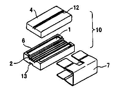
In drawings:
Fig. 1 is an exploded perspective view of a fiber
CA 02373579 2002-02-19
- 11 -
coupler 10 having a V-shaped groove, employed in an
example of the present invention;
Fig. 2 is a front view of the fiber coupler; and
Fig. 3 is a sectional view of the fiber coupler
taken from line III-III of Fig. 2.
Now, a process of the coupling method according to
the present invention will be described in reference to
the accompanying drawings. The present invention is not
limited to the embodiment shown in the drawings. Fig. 1
1o is an exploded perspective view of a fiber coupler 10
having a V-shaped groove as an example of the holder
employed in the coupling method according to the present
invention, Fig. 2 is a front view of the fiber coupler
10, and Fig. 3 is a sectional view of the fiber coupler
taken from line III-III of Fig. 2.
A lower holder 1 has a V-shape groove 2 having a V-
shaped section cut in an upper surface so as to extend in
a longitudinal direction of the upper surface. The V-
shape groove 2 may be single or comprise a plurality of
2o grooves. It is preferable that the lower holder 1 has a
ridge 6 formed by edges at four sides of the upper
surface. Since a cover 4 is combined with the lower
holder 1 inside the ridge 6, the cover can be located in
contact with outer circumferences of plastic optical
fibers so as to hold the plastic optical fibers in
reliable fashion even if the outer diameter of a plastic
optical fiber put in the groove 2 is greater than that of
CA 02373579 2002-02-19
- 12 -
the groove. It is preferable that the cover 4 has
opposite ends provided with inclined portions 5, and the
groove 2 has opposite ends provided with inclined
portions 3 in order to make introduction of the plastic
optical fibers smooth. It is preferable that one portion
of the lower holder 1 or the cover 4 is made of an
elastic material, such as rubber. When, for instance, a
contacting portion of the groove 2 with the plastic
optical fibers is made of rubber, the elasticity
so conveniently allows the plastic optical fibers to be held
therein in reliable fashion.
The lower holder 1 and the cover 4 are urged from a
direction perpendicular to the longitudinal direction of
the groove 2 by being sandwiched with a clip 7. It is
s5 preferable that the cover 4 and the lower holder 1,
respectively, have an upper surface and a lower surface
formed with a central recess 12 and a central recess 13
in the longitudinal direction of the upper surface and
the lower surface. This arrangement can prevent the
2o cover 4 or the lower holder 1 from slipping during
handling, making the handling easy by location at proper
positions, and make the handling easy even after both
members have been assembled. When the clip 7 has
projections formed thereon so as to be engageable with
25 the central recess 12 and the central recess 13, the clip
7 can be conveniently held without being slipped out of
the fiber coupler 10.
CA 02373579 2002-02-19
- 13 -
The fiber coupler 10 as the holder employed in the
present invention may be assembled by removing the cover
4 from the lower holder 1, applying a refractive index
matching agent in the groove 2, putting the cover 4 on
the lower holder 1 and sandwiching the cover 4 and the
lower holder 1 with the clip 7. Opposed end faces of
plastic optical fibers 8 and 9, which have been subjected
to smooth treatment, can be coupled by a simple process
wherein the end of one of the plastic optical fibers and
so the opposed end of the other plastic optical fiber are
introduced up to a location near to the center of the
fiber coupler 10 through the inclined portions 3, 5 and
are abutted together at that location, preferably with
the fiber coupler 10 being assembled. The cover 4 is
s5 preferably transparent or translucent so as to make the
coupled position of plastic optical fibers visible. The
material of the cover 4 may be resin or glass.
When it is not necessary to suppress splice loss at
a low level in particular, the refractive index matching
2o agent may be omitted. When it is not easy to introduce
the fibers 8, 9 because of a poor slide of the fibers 8,
9 into the fiber coupler 10, a silicone substance
providing a good slide or another substance may be
employed as the refractive index matching agent. A two
25 component adhesion, an ultraviolet cure adhesion and
another adhesion may be employed as the refractive index
matching agent. In that case, the clip 7 may be omitted
CA 02373579 2002-02-19
- 14 -
after bonding.
When the refractive index matching agent contains
bubbles, splice loss increases in hot environment in some
cases. When a two component adhesion is employed, it is
preferable to restrain bubbles from generating in mixture
by using one that the two components are independently
sealed in two adjacent sealed bags, and the two
components can be kneaded by connecting the bags.
Waiting for bubbles to disappear, or depressurizing to
so eliminate bubbles quicker is applicable. It is
applicable that two components are independently
introduced into two cylinders, the two cylinders have
leading edges provided with a static mixer, and the two
components axe mixed at the same time as the two
components are pushed out of the cylinders.
The lower holder 1 and the cover 4 are preferably
made of plastic because of quantity production by
injection molding. When the lower holder 1 and the cover
4 are made of plastic having thermal expansion properties
similar to plastic optical fibers, the coupled portion
has excellent temperature properties. When an
ultraviolet cure adhesion is employed as the refractive
index matching agent, the cover 4 is preferably made of
glass having a high optical transmittance to ultraviolet
light since the adhesive can be cured by a weak light
source for a short period of time.
CA 02373579 2002-02-19
- 15 -
EXAMPLE
Now, an example according to the present invention
will be specifically described. It is noted that the
explanation should not be used to limit the scope of the
present invention.
The lower holder 1 and the cover 4 are fabricated
from polycarbonate by injection molding so as to be
formed as shown in Figs. 1-3. The V-shaped groove 2 was
set at an opening angle of 60°. The inclined portions 3,
5 for introduction of plastic optical fibers were
inclined to main slant planes of the V-shaped groove 2 in
contact with the outer circumferences of optical fibers
at an angle of 30°, and the inclined portions are formed
on both ends of each of the cover 4 and the V-shaped
groove 2 of the lower holder 1. The clip 7 was formed
from a leaf spring having a thickness of 0.25 mm and made
of stainless steel. As the plastic optical fibers 8, 9
were employed plastic optical fibers, which had a central
portion made of transparent fluorine-containing resin and
2o a surrounding enforcing layer made of PMMA resin, and
having a diameter of 500 ~zm (manufactured by Asahi Glass
Company, Limited, commercially available under the
tradename of Lucina). The space that was defined by the
V-shaped groove 2 of the lower holder 1 and the cover 4
for holding the plastic optical fibers in a sectional
direction was determined at a distance that a cylindrical
space having a diameter of 400 um can be encompassed. As
CA 02373579 2002-02-19
- 16 -
the refractive index matching agent, a silicone oil was
employed.
The fiber coupler 10 was fabricated, having the
structure stated just above.
After the plastic optical fiber was cut by a razor,
the cut end faces were polished by a polishing sheet
having a grain size of 1 dun. When the cut fibers were
connected by the fiber coupler 10, the splice loss in
comparison with before cutting the plastic optical fiber
so was 0.1 d8. The end portions of the cut optical fibers
were able to be introduced into the groove in the fiber
coupler 10 through the inclined portions 3, 5 with the
lower holder 1 and the cover 4 being sandwiched by the.
clip 7.
~5 By the use of the flexibility of the holder with a
lateral pressure preliminarily applied thereto and the
toughness of plastic optical fibers, the plastic optical
fibers can be introduced into the groove without using a
wedge to open, the groove of the holder, which is located
2o between, e.g., the lower holder and the cover sandwiched
by the clip. As a result, a tool for preliminarily
holding a wedge is not needed. Coupling with splice loss
minimized can be established by abutting and coupling
opposed end faces of optical fibers. Additionally, it is
25 easy to carry out permanent coupling after temporary
coupling or to exchange an optical fiber with another
optical fiber at plural times since optical fibers can be
CA 02373579 2002-02-19
- 17 -
repeatedly introduced into and removed from the holder.
The entire disclosure of Japanese Patent Application
No. 2001-55169 filed on February 28, 2001 including
specification, claims, drawings and summary are
incorporated herein by reference in its entirety.