Sélection de la langue

Search

Sommaire du brevet 2374086 

Énoncé de désistement de responsabilité concernant l'information provenant de tiers

Une partie des informations de ce site Web a été fournie par des sources externes. Le gouvernement du Canada n'assume aucune responsabilité concernant la précision, l'actualité ou la fiabilité des informations fournies par les sources externes. Les utilisateurs qui désirent employer cette information devraient consulter directement la source des informations. Le contenu fourni par les sources externes n'est pas assujetti aux exigences sur les langues officielles, la protection des renseignements personnels et l'accessibilité.

Disponibilité de l'Abrégé et des Revendications

L'apparition de différences dans le texte et l'image des Revendications et de l'Abrégé dépend du moment auquel le document est publié. Les textes des Revendications et de l'Abrégé sont affichés :

  • lorsque la demande peut être examinée par le public;
  • lorsque le brevet est émis (délivrance).
(12) Demande de brevet: (11) CA 2374086
(54) Titre français: MECHE DE FRAISEUSE/PERCEUSE
(54) Titre anglais: MILL/DRILL BIT
Statut: Réputée abandonnée et au-delà du délai pour le rétablissement - en attente de la réponse à l’avis de communication rejetée
Données bibliographiques
(51) Classification internationale des brevets (CIB):
  • E21B 10/00 (2006.01)
  • E21B 10/42 (2006.01)
  • E21B 12/04 (2006.01)
  • E21B 29/06 (2006.01)
(72) Inventeurs :
  • THIGPEN, GARY M. (Etats-Unis d'Amérique)
  • KEITH, CARL W. (Etats-Unis d'Amérique)
(73) Titulaires :
  • VAREL INTERNATIONAL, INC.
(71) Demandeurs :
  • VAREL INTERNATIONAL, INC. (Etats-Unis d'Amérique)
(74) Agent: KIRBY EADES GALE BAKER
(74) Co-agent:
(45) Délivré:
(22) Date de dépôt: 2002-03-01
(41) Mise à la disponibilité du public: 2002-09-02
Licence disponible: S.O.
Cédé au domaine public: S.O.
(25) Langue des documents déposés: Anglais

Traité de coopération en matière de brevets (PCT): Non

(30) Données de priorité de la demande:
Numéro de la demande Pays / territoire Date
09/798,171 (Etats-Unis d'Amérique) 2001-03-02

Abrégés

Abrégé anglais


A drag type casing mill/drill bit for down hole milling of a casing window and
lateral drilling of a bore hole in an earth formation comprises a bit body
adapted to be
rotated in a defined direction. The bit body includes an operating end face
having a
plurality of radially extending blades formed as a part of the operating end
face of the
bit body. A plurality of primary cutting elements are individually mounted in
pockets
in one of the plurality of blades. In addition, a plurality of secondary ridge
structures
are mounted to each of the plurality of blades interspersed with the plurality
of
primary cutting elements in a pattern such that as the bit body rotates the
secondary
ridge structures contact the casing or the earth formation thereby protecting
the
primary cutting elements and allowing continuous substantially smooth casing
milling
and earth formation drilling.

Revendications

Note : Les revendications sont présentées dans la langue officielle dans laquelle elles ont été soumises.


8
WHAT IS CLAIMED IS:
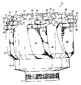
1. A drag-type casing mill/drill bit for down hole milling of a casing
window and drilling of a bore hole in an earth formation, comprising:
a bit body adapted to be rotated in a defined direction, the bit body having
an
operating end face;
a plurality of radially extending blades as a part of the operating end face
of
the bit body, the blades comprising pockets formed therein;
a plurality of primary cutting elements, each element mounted in a pocket in
one of the plurality of blades; and
a plurality of secondary ridge structures extending from each of the plurality
of blades interspersed with the plurality of primary cutting elements in a
cooperative
pattern such that as the bit body rotates at least one of the secondary ridge
structures
contact the casing or the earth formation thereby protecting the primary
cutting
elements and allowing substantially stable casing milling and earth formation
drilling.
2. A drag-type casing mill/drill bit as set forth in Claim 1, wherein the
secondary ridge structures extending from the plurality of blades comprise a
configuration of full or partial concentric rings.
3. A drag-type casing mill/drill bit as set forth in Claim 1, wherein the
plurality of primary cutting elements comprises a material such as PDC for
penetration into the casing and the earth formation.
4. A drag-type casing mill/drill bit as set forth in Claim 1, wherein the
plurality of secondary ridge structures comprise an elongated blunt
configuration
extending from the blades of the bit body to protrude therefrom in close
proximity to
a primary cutting element and extending from a surface of a blade to
substantially the
same height as an adjacent primary cutting element.
5. A drag-type casing mill/drill bit as set forth in Claim 1, further
comprising additional blunt ridge structures mounted to the operating end face
of the
bit body.

9
6. A drag-type casing mill/drill bit as set forth in Claim 1, wherein the
plurality of secondary ridge structures comprise cutting elements embedded in
a face
of the secondary structure.
7. A drag-type casing mill/drill bit as set forth in Claim 6, wherein the
cutting elements of the secondary ridge structures comprise a superhard
material such
as TSP.
8. A drag-type casing mill/drill bit for down hole milling of a casing
window and drilling of a bore hole in an earth formation, comprising:
a bit body adapted to be rotated in a defined direction, the bit body
comprising
an operating end face having a plurality of pockets formed therein;
a plurality of primary cutting elements, each element mounted in a pocket in
the operating end face; and
a plurality of secondary ridge structures extending from the operating end
face
interspersed with the plurality of primary cutting elements in a cooperative
pattern
such that as the bit body rotates at least one of the secondary ridge
structures contact
the casing or the earth formation thereby protecting the primary cutting
elements and
allowing substantially stable casing milling and earth formation drilling.
9. A drag-type casing mill/drill bit as set forth in Claim 8, wherein each
of the plurality of primary cutting elements comprises a cutting face oriented
in a
direction to contact the casing or the earth formation as the bit body rotates
in the
defined direction.
10. A drag-type casing mill/drill bit as set forth in Claim 9, wherein the
plurality of primary cutting elements are mounted to the operating end face of
the bit
body in a random pattern.

10
11. A drag-type casing mill/drill bit as set forth in Claim 8, wherein the
plurality of secondary ridge structures comprise an elongated blunt
configuration
extending from the operating end face of the bit body to protrude therefrom
and in
close proximity to a primary cutting element and extending from a surface of
the
operating end face to substantially the same height as an adjacent primary
cutting
element.
12. A drag-type casing mill/drill bit as set forth in Claim 11, wherein the
plurality of secondary ridge structures comprise cutting elements embedded in
a face
of the secondary ridge structure.
13. A drag-type drill bit for down hole drilling of a bore hole in an earth
formation, comprising:
a bit body adapted to be rotated in a defined direction, the bit body having
an
operating end face;
a plurality of radially extending blades as a part of the operating end face
of
the bit body, the blades comprising pockets formed therein;
a plurality of primary cutting elements, each element mounted in a pocket in
one of the plurality of blades; and
a plurality of secondary ridge structures extending from each of the plurality
of blades interspersed with the plurality of primary cutting elements in a
cooperative
pattern such that as the bit body rotates at least one of the secondary ridge
structures
contact the earth formation thereby protecting the primary cutting elements
and
allowing substantially stable earth formation drilling.
14. A drag-type drill bit as set forth in Claim 13, wherein the secondary
ridge structures extending from the plurality of blades comprise a
configuration of full
or partial concentric rings.
15. A drag-type drill bit as set forth in Claim 13, wherein the plurality of
primary cutting elements comprises a material such as PDC for penetration into
the
earth formation.

11
16. A drag-type drill bit as set forth in Claim 13, wherein the plurality of
secondary ridge structures comprise an elongated blunt configuration extending
from
the blades of the bit body to protrude therefrom in close proximity to a
primary
cutting element and extending from a surface of a blade to substantially the
same
height as an adjacent primary cutting element.
17. A drag-type drill bit as set forth in Claim 13, further comprising blunt
ridge structures mounted to the operating end face of the bit body.
18. A drag-type drill bit as set forth in Claim 13, wherein the plurality of
secondary ridge structures comprise cutting elements embedded in a face of the
secondary structure.
19. A drag-type drill bit as set forth in Claim 18, wherein the cutting
elements of the secondary ridge structures comprise a superhard material such
as TSP.
20. A drag-type drill bit as set forth in Claim 13, wherein each of the
plurality of secondary ridge structures comprises a leading end trailing a
leading end
of an adjacent primary cutting element, the leading end defined by direction
of
rotation of the bit body.
21. A drag-type drill bit for down hole drilling of a bore hole in an earth
formation, comprising:
a bit body adapted to be rotated in a defined direction, the bit body
comprising
an operating end face having a plurality of pockets formed therein;
a plurality of primary cutting elements, each element mounted in a pocket in
the operating end face; and
a plurality of secondary ridge structures extending from the operating end
face
interspersed with the plurality of primary cutting elements in a cooperative
pattern
such that as the bit body rotates at least one of the secondary ridge
structures contact
the earth formation thereby protecting the primary cutting elements and
allowing
substantially stable earth formation drilling.

12
22. A drag-type drill bit as set forth in Claim 21, wherein each of the
plurality of primary cutting elements comprises a cutting face oriented in a
direction
to contact the earth formation as the bit body rotates in the defined
direction.
23. A drag-type drill bit as set forth in Claim 22, wherein the plurality of
primary cutting elements are mounted to the operating end face of the bit body
in a
random pattern.
24. A drag-type drill bit as set forth in Claim 21, wherein the plurality of
secondary ridge structures comprise an elongated blunt configuration extending
from
the operating end face of the bit body to protrude therefrom and in close
proximity to
a primary cutting element and extending from a surface of the operating end
face to
substantially the same height as an adjacent primary cutting element.
25. A drag-type drill bit as set forth in Claim 24, wherein the plurality of
secondary ridge structures comprise cutting elements embedded in a face of the
secondary ridge structure.
26. A drag-type drill bit as set forth in Claim 21, wherein each of the
plurality of secondary ridge structures comprises a leading end trailing a
leading end
of an adjacent primary cutting element, the leading end defined by direction
of
rotation of the bit body.
27. A drag-type drill bit as set forth in Claim 1, wherein each of the
plurality of secondary ridge structures comprises a leading end trailing a
leading end
of an adjacent primary cutting element, the leading end defined by direction
of
rotation of the bit body.
28. A drag-type drill bit as set forth in Claim 8, wherein each of the
plurality of secondary ridge structures comprises a leading end trailing a
leading end
of an adjacent primary cutting element, the leading end defined by direction
of
rotation of the bit body.

Description

Note : Les descriptions sont présentées dans la langue officielle dans laquelle elles ont été soumises.


i
CA 02374086 2002-03-O1
MILL/DRILL BIT
TECHNICAL FIELD OF THE INVENTION
This invention relates to a combination mill/drill bit having primary cutting
elements and secondary structures, and more particularly to a combination
mill/drill
bit comprising primary cutting elements and secondary structures to enable
continuous substantially smooth milling of down hole casing and drilling of an
earth
formation.
1 o BACKGROUND OF THE INVENTION
Heretofore, the milling of down hole casing and the drilling of an earth
formation laterally from the casing were performed as two separate operations
requiring tripping the mill tool before sidetrack drilling of laterals in the
earth
formation. Milling tools for casing have typically been made of crushed
carbide to
provide sufficient cutting ability for the varying hardness of steel casing.
Typically, a
mill tool would be retrieved after milling a window in the down hole casing
and then
discarded.
The manufacturing process used in making prior art milling tools provided no
organization of the cutting structure; consequently, milling a window in a
down hole
2 0 casing became a lengthy and time consuming process. This is due to varying
down
hole conditions, operating parameters and applications. In many cases the
quality of
the manufacturing process for applying the cutting structure to a milling tool
depended upon the skill of the person applying the cutting structure.
Experience has
shown that present milling tools if used after cutting a window in a down hole
casing
would not be effective in drilling a lateral bore in most earth formations.
Thus the
milling tool must be tripped out of the well, a time consuming and costly
operation.
After tripping out the milling tool a second tool, that is a drill bit, suited
for drilling
formations of the earth would be tripped into the well to proceed with the
drilling
portion of the operation.
3 o Typically, the cutting element of an earth boring drill bit, although very
wear
resistant, could not survive the impacts of the interrupted cuts that occur
during
milling a window in steel casing. Thus the earth boring drill bit cannot be
used for
DAL01:660352

CA 02374086 2002-03-O1
2
both the milling operation and the drilling operation. When drill bits
designed for
boring in various earth formations were used for milling a window in a casing,
the
result was usually catastrophic in that most of the cutting elements were
broken
primarily resulting from the impact loads as the cutting elements enter and
leave the
steel casing during the window milling operation.
As a result of varying down hole conditions, performance of present
milling/drilling tools used to mill a casing window and then laterally drill
through an
earth formation produced varying results. To achieve some degree of uniformity
required extensive control of manufacturing processes to ensure quality tools
considered to be essential for consistent performance. The results have not
always
been encouraging and most operators prefer to trip the milling tool and run in
the drill
bit even though this was a time consuming and costly operation. Thus, there is
a need
for a mill/drill bit that will remain in the bore hole after window milling of
the steel
casing and continue with the drilling of laterals in the earth formation.
SUMMARY OF THE INVENTION
In accordance with the present invention there is provided a drag-type
mill/drill bit for down hole milling of a window in casing and lateral
drilling of an
earth formation that comprises a bit body adapted to be rotated in a defined
direction.
2 0 The bit body has an operating end face with a plurality of primary cutting
elements
each mounted in a pocket in the operating end face of the bit body. In
addition, a
plurality of secondary ridge structures are mounted to the operating end face
interspersed with the plurality of primary cutting elements in a pattern such
that as the
bit body rotates the secondary ridge structures contact the down hole casing
or the
2 5 earth formation thereby protecting the primary cutting elements and
allowing
continuous substantially smooth casing milling or earth formation drilling.
Also in accordance with the present invention there is provided a drag-type
mill/drill bit for a down hole milling of a window in casing and lateral
drilling of an
earth formation comprising a bit body adapted to be rotated in a defined
direction, the
3 0 bit body having an operating end face. A plurality of radially extending
blades are
formed as a part of the operating end face of the drill bit and a plurality of
primary
cutting elements are mounted in pockets in the plurality of blades. A
plurality of
DAL01:660352

i
CA 02374086 2002-03-O1
3
secondary ridge structures are also mounted to each of the plurality of blades
and
interspersed with the plurality of primary cutting elements in a pattern such
that as a
bit body rotates the secondary ridge structures contact the down hole casing
or the
earth formation thereby protecting the primary cutting elements and allowing
continuous substantially smooth casing milling or earth formation drilling.
The primary cutting elements and the secondary ridge structures are arranged
about the bit face to increase element contact during operation, particularly
when
interrupted cuts are taken while milling a window in steel casing. The
secondary
ridge structures may be configured in a pattern of full or partial concentric
rings or
1 o other beneficial shapes. The secondary ridge structures are positioned
such that as the
bit body rotates, one secondary ridge structure protrusion slides off the
steel or rock
and another secondary ridge structure protrusion comes in contact, allowing
continuous smooth drilling.
In another embodiment of the invention, the secondary ridge structures are
mounted adjacent to a primary cutting element to control the cutting depth of
the
primary cutting element. The leading edge of the secondary ridge structure
would be
positioned to expose the front face of the primary cutting element. Each
secondary
ridge structure has a leading edge configuration ramping up to the desired
height.
Technical advantages of the mill/drill bit of the present invention include
2 o utilizing the same primary cutting elements for both window milling of
steel casing
and drilling in earth formations of varying hardness. This results in a
substantial cost
saving by eliminating trip-out and trip-in when boring multiple laterals from
the same
casing. By use of the secondary ridge structures that allow continuous
substantially
smooth casing milling or earth formation drilling, there is achieved the
technical
2 5 advantage of reliable window milling in steel casing and improved
efficiency in
lateral bore hole drilling.
DAL01:660352

CA 02374086 2002-03-O1
4
BRIEF DESCRIPTION OF THE DRAWINGS
FIGURE 1 is a pictorial view of a mill/drill bit in accordance with the
present
invention;
FIGURE 2 is an end view of the operating end face of the mill/drill bit of
FIGURE 1;
FIGURES 3A, 3B, 3C and 3D illustrate the primary cutting elements and the
secondary structure for the mill/drill bit of FIGURE 1; and
FIGURE 4 is an illustration of the mill/drill bit of the present invention
cutting
a window in a casing.
DETAILED DESCRIPTION OF THE DRAWINGS
Referring to FIGURES 1 and 2, there is shown a mill/drill bit 10 embodying
the features of the present invention. As illustrated, the bit 10 has fixed
cutters
conventionally referred to in the industry as a drag bit. In accordance with
the present
invention, the fixed cutters also provide milling of windows in steel bore
hole casing.
Thus, the mill/drill bit 10 is adapted for milling a window in steel casing
followed by
drilling through earth formations to form lateral bore holes from the windowed
casing. The mill/drill bit 10 comprises a bit body 12, a shank 14 and a
threaded
connection or pin 16 for connecting the mill/drill bit 10 to a sub as a part
of a drill
2 0 string (not shown) in a manner conventional for processes of drilling in
the earth's
formations.
Bit body 12 includes a central longitudinal bore (not shown) as is
conventional
with drill bit construction as a passage for drilling fluid to flow through
the drill string
into the bit body and exit through nozzles 18 arranged in the operating end
face 20.
2 5 Extending from essentially the center of the operating end face 20 are
circumferentially spaced blades 22 that extend down the side of a bit body 10
as gage
pads to the shank 14. The bit body 10 is formed in a conventional manner
utilizing
either powdered metal tungsten carbide or steel bodies machined from a steel
block.
Attached to each of the blades 22 of the milling/drilling tool of the present
3 0 invention is a pattern of primary cutting elements 24 for milling through
casing and
creating a window into surrounding earth formations for lateral drilling. The
primary
cutting elements are polycrystalline diamond cutting inserts (PDC) or similar
DAL01:660352

CA 02374086 2002-03-O1
relatively hard material for milling the steel casing or boring into rock of
earth
formations. Intermixed with the primary cutting elements 24 are secondary
ridge
structures. The secondary ridge structures 26 have a relatively blunt
protrusion that
contacts the steel casing or the rock formations while the sharp primary
cutting
5 elements 24 is performing the milling/drilling operation. The blunt
configuration of
the secondary ridge structures 26 exhibits sliding contact with the steel
casing or the
rock formation to control the penetration of the sharp primary cutting
structure 24.
Thus, the secondary ridge structures 26 protrudes from the operating end face
20 in
close proximity to the primary cutting elements 24 and in operation protects
the
primary cutting elements during the milling/drilling operation by absorbing
impacts,
limiting the primary cutter engagement, controlling torque, and provide
stability.
The primary cutting elements 24 and the secondary ridge structure 26 are
arranged about the operating end face 20 to control contact of the primary
cutting
elements during a milling and/or drilling operation, particularly when
interrupted cuts
are taken during the milling of a window in steel casing. The secondary ridge
structures 26 may be configured as full or partial concentric rings or various
other
beneficial shapes to achieve the primary function of absorbing impacts. As
illustrated
in FIGURES 1 and 2 the secondary ridge structures 26 are positioned such that
as the
bit body 10 rotates, one secondary ridge structure protrusion slides off the
steel casing
2 0 or rock formation and another secondary ridge structure protrusion makes
contact
thereby protecting the primary cutting elements 24 and allowing substantially
continuous window cutting or drilling. For example, reference is made to the
radial
line 27 for an illustration of a secondary ridge structure 26 protecting a
primary
cutting element 24.
2 5 Additional relatively blunt ridge structures 28 are arranged around the
operating end face 20 at various locations to assist in stabilizing the bit
operation in
the event of a failure of an adjacent primary cutting element 24. The
additional blunt
ridge structures 28 may typically be cylindrical shaped with a flat cutting
surface.
Like the primary cutting elements 24 the additional blunt ridge structures 28
are
3 0 typically constructed from a relatively hard material.
Each of the primary cutting elements 24 are mounted in pockets formed in the
blades 22. As best illustrated in FIGURES 3A through 3D, the primary cutting
DAL01:660352

CA 02374086 2002-03-O1
6
elements 24 are constructed in accordance with conventional methods and each
typically includes a base or support 30 inserted into a pocket of a blade 22
and
secured within the pocket by brazing or similar conventional techniques. The
support
30 is typically a sintered tungsten carbide material usually with a hardness
exceeding
that of the bit body 10. Integral with the support 30 is a layer 32 of PDC
which forms
the cutting face of the primary cutting elements 24.
Also as illustrated in FIGURES 3A and 3C, the secondary ridge structures 26
may include crushed carbide cast into the structure surface. The secondary
ridge
structures 26 may also include TSP or diamond chips. Use of TSP, diamond chips
or
crushed carbide lessens the wear rate of the secondary ridge structure 26 and
also
imparts to the structure a secondary cutting operation.
Referring to FIGURE 4, there is illustrated use of the mill/drill bit of the
present invention illustrating the sequence of operation of the bit to form a
window in
a casing 34. The casing is cemented into the bore hole in accordance with
accepted
practice and a whip stock 36 is run into the hole and oriented such that the
concave
surface thereof is in the direction of the window to be cut in the casing 34.
The whip
stock 36 is anchored at a location in the casing 34 for cutting a window.
The mill/drill bit of FIGURES 1 and 2 is attached to a drill string 38 by
means
of the shank 14. The assembly is rotated in accordance with conventional
techniques
2 0 and as the bit encounters the whip stock 36 the primary cutting elements
24 begin to
cut into the casing 36 as shown by the bit in position A. The bit encounters
the
concave surface of the whip stock 36 and continues cutting into the casing 34
and
subsequently into the surrounding cement with the primary cutting elements 24
now
cutting the casing 34 and boring through the surrounding cement as illustrated
by the
2 5 bit at position B. As the mill/drill bit of the present invention is
nearing completion of
the cutting of a window in the casing 34 the primary cutting elements are now
boring
through the cement surrounding the casing and into the earth formation. Upon
completion of the cutting of the window in the casing 36 the mill/drill bit
continues to
bore into the earth formation and is now functioning primarily as an earth
boring bit.
3 0 Upon completion of the lateral bore hole the assembly including the
mill/drill bit of
FIGURES 1 and 2 is tripped out of the hole for subsequent use.
DAL01:660352

CA 02374086 2002-03-O1
7
Although the present invention has been described by reference to a preferred
embodiment, it will be appreciated by those skilled in the art that
modifications,
substitutions and additions may be made without departing from the scope of
the
invention as defined in the claims. The embodiment described herein is
exemplary
only, and is not limiting.
DAL01:660352

Dessin représentatif
Une figure unique qui représente un dessin illustrant l'invention.
États administratifs

2024-08-01 : Dans le cadre de la transition vers les Brevets de nouvelle génération (BNG), la base de données sur les brevets canadiens (BDBC) contient désormais un Historique d'événement plus détaillé, qui reproduit le Journal des événements de notre nouvelle solution interne.

Veuillez noter que les événements débutant par « Inactive : » se réfèrent à des événements qui ne sont plus utilisés dans notre nouvelle solution interne.

Pour une meilleure compréhension de l'état de la demande ou brevet qui figure sur cette page, la rubrique Mise en garde , et les descriptions de Brevet , Historique d'événement , Taxes périodiques et Historique des paiements devraient être consultées.

Historique d'événement

Description Date
Inactive : CIB de MCD 2006-03-12
Demande non rétablie avant l'échéance 2005-03-01
Le délai pour l'annulation est expiré 2005-03-01
Réputée abandonnée - omission de répondre à un avis sur les taxes pour le maintien en état 2004-03-01
Demande publiée (accessible au public) 2002-09-02
Inactive : Page couverture publiée 2002-09-01
Inactive : CIB en 1re position 2002-05-27
Inactive : CIB attribuée 2002-05-27
Demande reçue - nationale ordinaire 2002-04-02
Exigences de dépôt - jugé conforme 2002-04-02
Lettre envoyée 2002-04-02
Inactive : Certificat de dépôt - Sans RE (Anglais) 2002-04-02

Historique d'abandonnement

Date d'abandonnement Raison Date de rétablissement
2004-03-01

Historique des taxes

Type de taxes Anniversaire Échéance Date payée
Taxe pour le dépôt - générale 2002-03-01
Enregistrement d'un document 2002-03-01
Titulaires au dossier

Les titulaires actuels et antérieures au dossier sont affichés en ordre alphabétique.

Titulaires actuels au dossier
VAREL INTERNATIONAL, INC.
Titulaires antérieures au dossier
CARL W. KEITH
GARY M. THIGPEN
Les propriétaires antérieurs qui ne figurent pas dans la liste des « Propriétaires au dossier » apparaîtront dans d'autres documents au dossier.
Documents

Pour visionner les fichiers sélectionnés, entrer le code reCAPTCHA :


Pour visualiser une image, cliquer sur un lien dans la colonne description du document. Pour télécharger l'image (les images), cliquer l'une ou plusieurs cases à cocher dans la première colonne et ensuite cliquer sur le bouton "Télécharger sélection en format PDF (archive Zip)" ou le bouton "Télécharger sélection (en un fichier PDF fusionné)".

Liste des documents de brevet publiés et non publiés sur la BDBC .

Si vous avez des difficultés à accéder au contenu, veuillez communiquer avec le Centre de services à la clientèle au 1-866-997-1936, ou envoyer un courriel au Centre de service à la clientèle de l'OPIC.


Description du
Document 
Date
(aaaa-mm-jj) 
Nombre de pages   Taille de l'image (Ko) 
Dessin représentatif 2002-05-28 1 17
Page couverture 2002-08-30 1 48
Description 2002-03-01 7 326
Dessins 2002-03-01 3 103
Abrégé 2002-03-01 1 22
Revendications 2002-03-01 5 203
Courtoisie - Certificat d'enregistrement (document(s) connexe(s)) 2002-04-02 1 113
Certificat de dépôt (anglais) 2002-04-02 1 164
Rappel de taxe de maintien due 2003-11-04 1 106
Courtoisie - Lettre d'abandon (taxe de maintien en état) 2004-04-26 1 175