Note : Les descriptions sont présentées dans la langue officielle dans laquelle elles ont été soumises.
02-07-2001 1B000021 C
CA 02375610 2002-01-04
CONNECTING DEVICE FOR TUBULAR FRAMIE MEMBERS, PARTICULARLY
FOR STRETCHER.
TECHNICAL FIELD
This invention relates to medical devices to be used in first aid emergency
situations for
immobilizing and canying the traumatized injured persons.
Particularly the invention refers to a connecting device for tubular frame
members of a
io scoop stretcher with which is possible to "pick-up" an injured person
laying on the ground
without any risk to let him suffer more possible trauma.
BACKGROUND OF THE IIWENTION
The known scoop stretchers essentially consist of two half-stretchers
detachably connected
near to the ends by means of articulated hooking devices.
Document US-A-3.653.079 discloses a pivot lock for splint-stretcher
essentially consisting
of a female part including a "U" shaped seat transversely crossed, in a
substantially central
position, by a hooking pivot and of a male part made of a tongue which is
complementarily
inserted into the "U" shaped seat and its head.is provided with a notch fit
for partially
-_, ._ .-housing the-pivot pinand fitfio-be closed-at -eyelet-by-a iatch
member o~opeizfturgWitlrit =-~ s
in order to "hook" the pivot pin by way of eyelet. This latch member is
pivotally connected
to the tongue and is kept in the eyelet-closure condition by a contrast
spring.
The main drawback of the known connection and coupling devices for stretchers
is that
they can be accidentally opened, with very serious consequence for the patient
carried by
the stretcher, especially when the stretcher is handled by the operators
particularly in
narrow environments (ditch, inside the vehicles, etc.) or in situations
hurried up by the
emergency and quickness of the intervention.
To prevent the opening and then the accidental disconnection of the device, it
was
AMENDED SHEET
CA 02375610 2002-01-04
WO 01/03628 PCT/IB00/00210
suggested to use a safety hook assembled on the female part whose hooking end
engages a
recess made in the tongue of the male part in correspondence of the coupling
condition.
Such solution, notwithstanding represents an effective remedy against the
accidental
opening of the device, has however the disadvantage of being not very reliable
in case of
malfunction or failure of the hooking member.
In fact, the hooking members have load function since the weight of the
carried patient acts
thereon because the stresses are transferred from the two half-stretcher
through the tubular
frame members to the hooking and locking members.
Other disadvantage of the known solutions is that the closing or opening of
the stretcher by
the operator is uncomfortable, because the hook of the device is positioned in
the inner side
of the stretcher, in other words in correspondence of the area of the head or
feet of the
transported injured person.
Furthermore, the solution that presents a safety hook, for coupling or
uncoupling the half-
stretcher, requests to act on the free ends of both hooks, by using both
hands.
Consequently, such operations are uncomfortable because of the inappropriate
positions of
the operator hands and because the coupling/uncoupling button of the main
locking hook
member is placed in the inner edge of the stretcher.
DISCLOSURE OF THE INVENTION
The main object of the present invention is to propose a connecting device for
preventing
the opening and the accidental disconnection of said device, particularly due
to shocks or
malfunction of the device.
Other object is to propose a device for allowing a comfortable coupling and
uncoupling of
the half-stretcher by the operator.
A further object is to propose a device simple and easy to be made and to be
maintained.
2
CA 02375610 2002-01-04
WO 01/03628 PCT/IBOO/00210
These and other objects and advantages of the present invention will become
apparent
from the subsequent detailed description of best mode for carrying out the
invention and
appended claims taken in conjunction with the accompanying drawings.
DESCRIPTION OF THE DRAWINGS
- Figure 1 shows a reduced schematic view, in a coupled condition, of the half-
stretchers
interconnected by means of the connecting device according to the present
invention;
- figure 2A and 2B show a schematic view, respectively in a uncoupled and a
partially
coupled condition, of the half-stretchers in figure 1;
- figure 3 shows a front view of the device according to the present invention
in a
coupled condition;
- figure 4 shows a top view of the device in figure 3;
- figure 5 shows a section view of the device in figure 3;
- figure 6 shows a top view of the device in figure 3 in a partial coupled
condition;
- figure 7 shows a top view of the device in figure 3 in a uncoupled
condition;
- figure 8 shows a top view of the device in figure 3 in a coupled and folded
up
condition;
- figure 9 shows a top view of a stretcher portion in a coupled condition in
which some
parts have been removed for better viewing other parts;
- figure 10 shows a partial section view of the device taken along the line X-
X in figure
9;
- figure 11 shows a top view of a variant of the device according to figure 3,
in an
uncoupled condition;
- figure 12 shows a top view of the device in figure 11 in a partial coupled
condition;
- figure 13 shows a top view of the device in figure 11 in a coupled and
folded up
condition;
- figure 14 shows a front view of the device in figure 11 in a coupled
condition;
- figure 15 shows a top section view of the device in figure 11 in a coupled
condition;
- figure 16 shows a front section view of the device in figure 11 in a folded
and partially
coupled condition.
3
CA 02375610 2002-01-04
WO 01/03628 PCT/IB00/00210
BEST MODE FOR CARRYING OUT THE INVENTION
Referring to figures 1, 2A and 2B, numeral 1 indicates a connecting device of
a scoop-
stretcher 3, composed by two half-stretchers, first 3a and second 3b, whose
respective
lateral and peripheral supporting tubular frame members, first 2a and second
2b, are
detachably connected by means of a device 1.
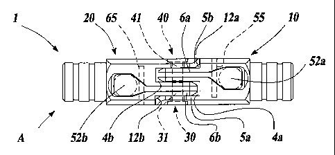
Referring to figures from 3 to 7, the device 1 comprises a pair of elements of
the same
embodiment and shape, essentially including connecting means, first 10 and
second 20;
support means, first 30 and second 40; hooking and locking means, first 50 and
second 60.
Each of the connecting means, 10 and 20, is fixed to the respective tubular
frame member
2a and 2b and they are complementarily connectable in correspondence of a
coupling
condition A between the tubular frame members 2a and 2b.
Each of the connecting means, first 10 and second 20, has, on the free end, a
seat,
respectively first 4a and second 4b, defined by a bracket, respectively first
5a and second
5b, and a tongue, respectively first 6a and second 6b, in such a way that each
tongue 6a,
6b, is placed substantially parallel to the relative bracket 5a, 5b.
In this way the two connecting means 10 e 20, are complementarily connectable
in such a
way that the second tongue 6b is detachably insertable into the first seat 4a,
and the second
bracket 5b overhang the first tongue 6a, while the first tongue 6a is
detachably insertable
into the second seat 4b, and the first bracket 5a overhangs the second tongue
6b.
The support means, first 30 and second 40, essentially comprise respectively a
first pivot
pin 31 and a second pivot pin 41, fixed perpendicularly, respectively to the
inside wall of
first bracket 5a and second bracket 5b.
Each tongue, first 6a and second 6b, has a recess, respectively first 8a and
second 8b fit for
housing the corresponding second pivot pin 41 and first pivot pin 31.
4
CA 02375610 2002-01-04
WO 01/03628 PCT/IB00/00210
The hooking and locking means, first 50 and second 60, are respectively
pivoted by means
of related pins, first 55 and second 65, to the connecting means, first 10 and
second 20, and
are fit to hook the respective pivot pins, second 41 and first 31, in
correspondence of the
coupling condition A.
Each of the hooking means, first 50 and second 60, includes a hook,
respectively first 9a
and second 9b, whose free end is insertable in the corresponding tongue,
respectively first
6a and second 6b, in such a way to hook the corresponding pivots, second 41
and first 31,
in correspondence of the coupling condition A.
The hooking means, first 50 and second 60, are inside a correspondent housing,
first 54
and second 64, of the connecting means, 10 and 20, in such a way that the
operating free
ends, first 52a and second 52b, of the hooking means, first 50 and second 60
are placed on
the plane defined by the side surfaces of the connecting means, 10 and 20. In
this way such
operating free ends or buttons are faced outwardly with respect to the
stretcher 3 so as to
be faced to the operator carrying it.
Furthermore, the hooking means, 50 and 60, are permanently kept in the
coupling
condition A by means of the elastic reaction of the respective elastic means,
first 51a and
second 51b, for example springs, interposed respectively between the lower
walls of the
operating buttons, 52a and 52b, and the bottom of the related housing, first
54 and second
64, of the connecting means, 10 and 20.
In figures 9 and 10 is shown a variant of the device 1 which has anchorage
means 70,
essentially composed by inserts 71, fixed to the connecting means, first 10
and second 20,
fit to lock these latter to the frame of the stretcher 3. In particular each
anchorage means 70
is provided with three inserts 71 inserted in the plastic material during the
forming of each
half-stretcher frame.
The utilization of the device 1 is extremely simple and reliable, because the
operator, after
approaching the two tubular frame members, 2a and 2b, in order to join them
through the
device 1, has to press onto the operating buttons 52a and 52b or to approach
forcedly the
5
CA 02375610 2002-01-04
WO 01/03628 PCT/IB00/00210
two tubular frame members 2a and 2b, in order to overcome the strength exerted
by the
elastic reaction of the springs 51a and 51b and thus to push away the hooks 9a
and 9b from
the pivot 31 and 41. At this point the operator approaches furthermore the two
tubular
frame members and hence the connecting means, 10 and 20, until the first
bracket 5a and
first tongue 6a insert in the respective housing made in the second connecting
means 20,
namely in second seat 4b and in a second notch 12b. Similarly, the second
bracket 5b is
inserted in a first notch 12a and the second tongue 6b is inserted into the
first seat 4a.
These connections take place until the pivots, first 31 and second 41, engages
the bottom
1o of the correspondent recesses, second 8b and first 8a, and therefore the
safe and stabile
hooking of the pivots, first 31 and second 41, is firmly and safely obtained
by means of the
hooks, respectively first 9a and second 9b.
It is advantageous to notice that the above mentioned hooking, that is
achieved also if the
operating buttons 52a and 52b are not operated, is allowed by virtue of
inclined leading
edges, first 19a and second 19b, made on the head of the related hooks 9a and
9b.
In such a way the coupling condition A is operated, while the reversed
operations lead to
the uncoupling condition D, shown in details in figure 6, provided that the
operator, using
normally both the hands, press on the operating buttons, 52a and 52b, in order
to release
the hooks 9a and 9b from the support means 30, 40 in correspondence of the
uncoupling
condition D of the tubular frame members 2a and 2b.
Therefore it is necessary to release both the hook means 50, 60 from the
support means 30,
40 in order to separate the connecting means first 10 and second 20, one from
the another.
In a variant of the invention, the connecting means, first 10 and second 20,
are pivotally
constrained to the tubular frame members, respectively first 2a and second 2b.
It is convenient to specify that the connecting means, first 10 and second 20,
have a
chamfer edge, respectively first 11a and second 11b, in correspondence of a
free end of the
connecting means 10, 20 to allow the mutual rotation around the support means
30, 40 in
6
CA 02375610 2002-01-04
WO 01/03628 PCT/IB00/00210
the approach direction, shown by the arrows R1 and R2 of figure 8, of the free
ends of the
hooking means, first 50 and second 60, in correspondence of a mutual folding
condition P
of the two half-stretcher 3a, 3b.
The tubular frame members, first 2a and second 2b, are therefore detachable by
moving
them according to the arrows S of figure 7 because none of the two hooks 9a
and 9b is
hooked to the complementary pivot pin 31, 41.
The two tubular frame members 2a and 2b cannot be released whether only the
first hook
lo 9a is disconnected from the second pivot 41, and similarly whether only the
second hook
9b is disconnected from the first pivot 31.
The release of the two tubular frame members 2a and 2b happens only if both
the hooks 9a
and 9b are disconnected from the complementary pivots 41 and 31.
This solution is therefore fit for preventing accidental opening of the
stretcher particularly
due to malfunction of the device, for example an unexpected failure of the
contrast spring
of anyone of the hooks, because the two tubular frame members are still
connected steadily
by means of the remaining hook.
In the variant shown in figures from 11 to 16 the seats, first 4a and second
4b, are
longitudinally extended by means of shaped recesses, respectively first 4c and
second 4d,
fit to allow the free rotation respectively of the hooks 9b and 9a in
correspondence of the
folded condition P of said two half-stretcher 3a, 3b.
The heads of said hooks, first 9a and second 9b, have inclined leading edges,
respectively
first 19a and second 19b, approximately shaped as a circumference arch, and
the
correspondent tongues, respectively first 6a and second 6b, have recesses,
respectively first
8a and second 8b, "V" shaped in such a way to allow the coupling or the
uncoupling of
said connecting means, first 10 and second 20, also in correspondence of the
mutual folded
condition P.
7
CA 02375610 2002-01-04
WO 01/03628 PCT/IB00/00210
It is important to notice that by virtue of these variant, said connecting
means, first 10 and
second 20, can be rotated from the respective straight coupled condition A of
180 till the
folded condition P up to less than 90 .
Besides, this variant allows also the coupling and uncoupling operations in
correspondence
of angles between the longitudinal axis of the connecting means, first 10 and
second 20,
varying from 180 up to less than 110 in order to easily assemble and
disassemble the two
half shelves of the stretcher 3.
1o More precisely, the connecting means, first 10 and second 20, also if in
the folded
condition P, can be hooked moving them in the direction of the arrows A1 of
figures 11
and 12, until the pivots, first 31 and second 41, engage the bottom of the
correspondent
recesses, second 8b and first 8a, and so obtaining the safe and stabile
hooking and locking
of the pivots, first 31 and second 41, by means of the hooks, respectively
first 9a and
second 9b (see figure 11).
The connecting means, first 10 and second 20, can mutually rotate in the
approaching
direction so reaching an extreme folded condition. The connecting means, first
10 and
second 20, can be detached in the folded condition P by pressing on the
operating buttons,
52a and 52b, in order to disengage the hooks 9a and 9b from the support means
30, 40 and
moving them in opposite directions.
According to the preferred embodiment an the variants of the device 1, it is
important to
notice that the two hook 9a and 9b avoid the accidental opening of the device
1 in case of
knock of anyone of the two operating buttons 52a and 52b during the carriage
of the
stretcher 3, for instance in difficult situation, because the possible
disconnection of an hook
do not cause the opening of the stretcher since the other hook is always
engaged with the
correspondent pivot: thus this device has double linking, supporting and
locking hook
members which could be considered a "redundant system" but it is extremely
efficient and
safe in order to avoid accidental and inopportune opening of the stretchers.
Advantageously the two hook 9a and 9b are placed in correspondence of the
external
8
CA 02375610 2002-01-04
WO 01/03628 PCT/IB00/00210
lateral walls of the connecting means, first 10 and second 20, so that their
operative free
ends, first 52a and second 52b, face the operator.
Furthermore, the brackets, first 5a and second 5b, have related beveled edges
15 and the
tongue, first 6a and second 6b, have correspondent beveled edges 16 in such a
way to easy
the coupling/uncoupling thereof, that is of the connecting means, first 10 and
second 20.
In this way the coupling and uncoupling operation of the half-stretchers 3a
and 3b becomes
very simple because the operator puts the hands in a natural position without
interfering
lo with the body of the patient carried by the stretcher 3.
It is very important to specify that such connecting device 1 is usable not
only for coupling
the tubular frame members of the two half-stretchers in a scoop-stretcher 3,
but it is also
used to connect the heads of two tubular frame members of general use in such
a way to
allow the uncoupling, even if they are subjected to torsion and/or flexion,
and anyhow such
device is able to prevent the accidental disconnection.
The main advantage of the present invention is to provide a connecting device
for a
stretcher fit to allow the coupling/uncoupling of two tubular frame members of
the scoop-
stretcher, also in correspondence of flexion and/or torsion condition of the
stretcher
portions disclosed by the present invention, and to avoid the accidental
opening of the
same device and therefore the accidental uncoupling of the two tubular frame
members of
the stretcher, particularly in consequence of malfunctions or failures of some
coupling
device element or accidental knocks.
Other advantage of this invention is to provide a handy device, fit to allow
both an easy
operation of the coupling device and the coupling and the uncoupling of the
connecting
means also in correspondence of the mutual folded condition.
Further advantage is to provide a connecting device of simple production, at
low cost and
with high level of reliability.
9