Note : Les descriptions sont présentées dans la langue officielle dans laquelle elles ont été soumises.
CA 02376692 2002-03-13
RAILING APPARATUS WITH VARIABLE POSITIONABLE RAILS
BACKGROUND OF THE INVENTION
This invention relates to railing apparatuses and, in particular, to railing
apparatuses
having rails which can be adjusted to different angular positions relative to
the posts
thereof.
The prior art reveals numerous different railing apparatuses for use in such
applications
as stairways, decks and balconies. Typically these apparatuses are shipped to
a job site as
a plurality of components which axe assembled and installed at the required
location.
One factor which increases the cost of such railing systems is the necessity
to
accommodate different configurations of components. In some cases the number
of
separate components is multiplied because different components are required
for different
installation situations. For example, the most common installation is one
where the rails
are perpendicular to the posts and are aligned with each other in a common
direction.
Alternatively corner posts receive rails at right angles to each other.
Different posts or
different fittings are then required for rails used on stairs where the rails
are angled with
respect to the posts. Different posts or different fittings again are required
for situations
where the rails connect to the posts at non-perpendicular angles in a
horizontal plane.
Meeting all of these requirements means a larger number of components have to
be
produced or customized for different installations.
It is an object of the invention to provide an improved railing apparatus
where a reduced
number of components can be utilized for different installation conditions.
It is also an object of the invention to provide an improved railing apparatus
where a
single type of post can receive rails projecting at different angles with
respect to the post.
CA 02376692 2002-03-13
-2-
It is a further object to the invention to provide an improved railing
apparatus which is
economical to produce and sell and provides a rugged and long-lasting
installation.
SUMMARY OF THE INVENTION
According to the invention, there is provided an aluminum railing apparatus
having a rail
with an end. There is a post for supporting the rail, The post has a side and
an opening
in the side for receiving the end of the rail. The opening has a profile
equivalent to a
profile of the rail along a first plane. The first plane is inclined with
respect to a second
plane. The second plane is transverse relative to the rail, whereby an end of
the rail can
be inserted through the opening so the rail is at an angle inclined with
respect to a
position of the rail perpendicular to the side of the post. There is a
securing device which
secures the rail to the post at said angle.
In one embodiment, the rail is a top rail. The railing apparatus also includes
a bottom
rail. The side of the post includes a lower opening for receiving the end of
the bottom
rail. The lower opening has a profile the equivalent to a profile of the
bottom rail along a
second plane. The second plane is inclined with respect to a third plane. The
third plane
is transverse relative to the bottom rail. An end of the bottom rail can be
inserted through
the lower opening so the bottom rail is at said angle. There is a securing
device which
secures the end of the bottom rail to the post at said angle.
The invention offers significant advantages compared to the prior art. It
allows a single
type of post, rail and securing device to be utilized in different
installation situations
where the rail projects at different angles from the post. At the same time,
the connection
of the post to the rail is quite simple, whereby the rails fit in precut
openings in the post,
within a range of different angular positions, and are then secured by the
securing device.
The manufacturer accordingly does not have to provide different types of
posts, railings
or securing devices for each of the different angular positions within this
range. This
means that the number of components to be stocked and shipped is significantly
reduced.
For the manufacturer this reduces overhead and manufacturing costs. For the
installer it
CA 02376692 2002-03-13
-3-
means simplified ordering procedures since fewer customized components are
required.
It is less likely that the job will be held up because of the shortage of
certain types of
components because components according to the invention are adaptable to a
number of
different installation situations.
BRIEF DESCRIPTION OF THE DRAWINGS
In the drawings:
Figure 1 is an isometric view of a railing apparatus according to an
embodiment of the
invention;
Figure 2 is exploded isometric view thereof;
Figure 3 is an enlarged, fragmentary exploded view of a center post therefor
and portions
of the rails and other components connected thereto;
Figure 4 is a top plan, diagrammatic view of the post thereof and rails
connected to the
post at different angular positions;
Figure 5 is a view similar to Figure 3 for an end post thereof;
Figure 6 is a view similar to Figure 4 for the post of Figure 5;
Figure 7 is a view similar to Figure 3 for a post at the top of a stairway
which connects
two aligned horizontal rails;
Figure 8 is a view similar to Figure 4 for the post of Figure 7;
Figure 9 is a view similar to Figure 3 for a corner post;
CA 02376692 2002-03-13
-4-
Figure 10 is a view similar to Figure 4 for the post of Figure 9;
Figure 11 is a view similar to Figure 7 for a stand-alone post at the top of a
stairway; and
Figure 12 is a diagrammatic inside elevation showing the connection of a rail
thereof to
the post at different angles of inclination;
Figure 13 is enlarged, fragmentary sectional view of the embodiment of Figure
1 showing
a picket assembly; and
Figure 14 is a view similar to Figure 13, showing the glass panel assembly;
Figure 15 is a front view of the cutout in the post for the top rail and the
top rail of Figure
7;
Figure 16 is a view similar to Figure i 5 for a straight top post cutout and
the top rail;
Figure 17 is a view similar to Figure 16 for a 22.5 degree top post cutout and
the top rail;
Figure 18 is a view similar to Figure 16 for a straight bottom post cutout and
the bottom
rail;
Figure 19 is a view similar to Figure 18 for a 22.5 degree bottom post cutout
and the
bottom rail;
Figure 20 is a view similar to Figure 15 showing the opening in the post only;
Figure 21 is a view similar to Figure 18, but showing the opening only for use
on stairs as
in Figure 7; and
CA 02376692 2002-03-13
- 5 -
Figure 22 is a view similar to Figure 21, but showing the cutout only for a
straight bottom
post.
DETAILED DESCRIPTIONS OF THE PREFERRED EMBODIlVIENTS
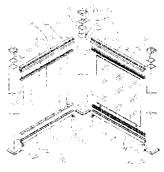
Referring to the drawings and first to Figure l, this shows a railing
apparatus 20
according to an embodiment of the invention. The railing apparatus includes
two end
posts 22 and 24, a corner post 26, first top rail 28, a second top rail 30,
first bottom rail 32
and a second bottom rail 34. A plurality of pickets 36 extend between the top
rail 28 and
bottom rail 32. The pickets could be of other sizes, shapes and configurations
than those
illustrated. A glass panel 40 extends between the top rail 30 and bottom rail
34.
Typically either pickets or similar panels would be used throughout the same
installation,
but for illustrative purposes this example has both a glass panel and pickets.
Each of the
posts is equipped with a top cap 42 and a mounting plate 44 at the bottom
thereof. Each
of the mounting plates has a plurality of apertures 46 for securing the
railing apparatus to
a surface such as a wooden deck or a concrete pad. Typically screws, bolts or
studs
project through the apertures and are fitted with compatible nuts.
More of the details of the invention are apparent in Figure 2 which is an
exploded view of
the apparatus of Figure 1. The rails project through openings in each of the
posts. For
example, end 50 of top rail 30 projects through opening 52 of post 26.
Likewise end 54 of
top rail 28 projects through opening 56 of the same post. End 60 of bottom
rail 34
projects through opening 62 in the post and end 64 of bottom rail 32 projects
through
opening 66. It may be observed that the openings in the posts are shaped
similar to the
profiles of the rails as may be seen by comparing end 68 of rail 30 with
opening 52 and
comparing end 70 of rail 34 with opening 62. However, as will be explained in
more
detail below, the openings have increased dimensions to permit the rails to be
positioned
at different angles other than completely perpendicular to sides 72 and 74 of
post 26 as
illustrated. In brief, the opening in the post has a profile similar to the
transverse exterior
profile of the rail, but is enlarged relative to the profile of the rail so
one end of the rail
CA 02376692 2002-03-13
can be inserted through the opening and the rail is at a non-perpendicular
angle relative to
the post.
The posts are hollow in this example, having a space therein which is
rectangular in
section as may be observed by the hollow interior 80 of post 26. The term
"rectangular"
is used herein in the broader sense to include a space which is square in
section as may be
observed in the illustrated embodiment. There is a device for securing the end
of each
rail to the appropriate post. For example, the securing device is in the form
of a plate 82
which fits within post 26 and secures end 54 of rail 28 and end 50 of rail 30.
In this
example the plate 82 is square in section and fits closely inside the post 26.
A plurality of
screws 86 extend through apertures 88 in the plate and into the ends of the
rails. U-
shaped clips 90 are connected to the bottom rails by screws 92. They butt
against raised
edge 63 on the post to properly locate the bottom rails.
A variation of the invention shown in Figure 3 wherein like parts have like
numbers as
the previous embodiment with the additional designation ".1 ". In this case
post 94
receives top rails 28.1 and 30:1 which are aligned in a linear manner. Bottom
rails 32.1
and 34.1 are similarly aligned. However, as seen in Figure 4, the rails may be
angled at
different positions compared to the position 180 degrees apart as illustrated
in Figure 3.
The minimum angle of 150 degrees is illustrated by the positions of the rails
illustrated in
broken lines at 96 and 98. The maximum angle of 210 degrees is illustrated in
broken
lines at 100 and 102.
The profile of each of the openings is generally similar to the profiles of
the rails. This
may be observed by comparing the profiles of rails 28.1 and 32.1 with the
openings 52.1
and 62.1. However the openings are actually wider than the rails to
accommodate the
angular displacements apparent in Figure 4. The actual width of each of the
rails and the
openings varies from top to bottom as may be observed. However Figure 4 shows
a
typical section. Opening 54.I has opposite sides 106 and 108. A first plane
110 through
the rail is inclined with respect to a second plane 112 through the square end
of the rail.
The second plane is accordingly transverse relative to the longitudinal
direction of the
CA 02376692 2002-03-13
_7_
rail. It may be seen that the width of the opening between sides 106 and 108
is
substantially the same as the width of the rail taken along the first plane.
In fact the
opening is slightly wider than the rail at this point to allow insertion of
the rail through
the opening, but the dimensions are substantially the same. Likewise the width
of the
opening is equivalent to the width of the rail, taken along plane 110 at
different vertical
positions along the rail and the opening. Thus the opening has a profile
equivalent to a
profile of the rail along the first plane 110 which allows the rail to be
inserted at an
inclined angle, as represented by the position shown in broken lines in Figure
4, relative
to the position of the rail perpendicular to side 113 of the post. Although
described above
in relation to top rail 30.1, the same relationship applies between bottom
rail 34.1 and
opening 62.1 as well as the corresponding top and bottom rails and openings on
the
opposite side of the post.
Figures 5 and 6 illustrate an end post 116 with openings 52.2 and 62,2. In
this example
the same numbers are used for similar components as in the previous
embodiments with
the additional designation ".2". The relationship between the profiles of
rails 30.2 and
34.2 and the openings is the same as described above for the embodiment of
Figures 3
and 4. However this is an end post so there is no opening on the side opposite
openings
52.2 and 62.2. As illustrated in Figure 6, the rails are adjustable from 75
degrees to 105
degrees relative to side 113.2 of post 116.
Figures 7 and 8 illustrate a center post 120 which is generally similar to
post 94 of Figure
3. In this example the same numbers are used for similar components as in the
previous
embodiments with the additional designation ".3". However, as illustrated in
Figure 8,
the post is configured to allow a wider degree of angular displacement of the
rails in
horizontal plane between 129 degrees and 23I degrees. This is accomplished by
making
the openings 52.3 and 62:3 wider at corresponding positions than the openings
52.1 and
62.1 in Figure 3.
However there is a further difference due to the fact that rails 30.3 and 34.3
are inclined
downwardly from left to right, from the point of view of Figure 7, for use on
a stairway
CA 02376692 2002-03-13
_g_
for example with post 120 at the top of the stairway. Accordingly, in this
example the
first plane is represented by a plane through end 124 of the rail 30.3 which
is inclined
with respect to a second plane which is transverse relative to the rail as
represented, for
example, by the square end 126 of rail 20.3. Again the profile of opening 52.3
appears
similar to the profile at end 126 of the rail 28.3, but is actually higher to
accommodate the
angular displacement of the rail. Correspondingly opening 62.3 is higher than
the profile
of rail 34.3 when viewed directly on the end thereof.
Figures 9 and 10 show on alternative corner post similar to post 26 of Figure
1. In this
example the same numbers are used for similar components as in the previous
embodiments with the additional designation ".4". The post 24.1 has openings
52.4 and
62.4 for rails 30.4 and 34:4. It also has openings 56.4 and 66.4 for rails
28.4 and 32.4. In
this example, as seen in Figure 10, the openings are sufficiently wide to
provide for an
angular displacement of the rails 28.4 and 30.4, as well as the corresponding
bottom rails,
between 60 degrees and 120 degrees.
Figures 11 and 12 show a post 130 which is similar to the post 120 of Figures
7 and 8. In
this example the same numbers are used for similar components as in the
previous
embodiments with the additional designation ".5". However in this example the
post 130
is an end post and accordingly only has openings 52.4 and 62.4 for a pair of
rails 30.5 and
34.5. Figure 12 illustrates how opening 52.4 is elongated vertically in order
to
accommodate rail 30.4 at angles between 35 degrees and 39 degrees to the
horizontal as
represented by line 134.
Referring back to Figure 2, it should be understood that in some embodiments
the
structure would be complete with only the top rails 28 and 30 and without the
bottom
rails 32 and 34 or the structures in between. However optionally, as
illustrated in Figure
2, there are bottom rails 32 and 34 as well as pickets 36 and/or glass panel
40.
In this example each of the pickets 36 has a top 150 and a bottom 152. The
tops are
connected to a top elongated member 154, while the bottoms are connected to a
bottom
CA 02376692 2002-03-13
-9-
elongated member 156. These are shown better in Figure 13. The top rails have
a
downwardly facing channel 160 including slots 162 and 164. The top elongated
member
154 has flanges 166 and 168, shown in Figure 2, which fit into the slots of
the
downwardly facing channel. The member 154 also has a pair of shorter flanges
155 and
157 located inwardly with respect to flanges 166 and 168. These flanges each
have a
groove 159 which engages lip 161ofthe rail. Similarly the bottom elongated
member fits
within slots 170 and 172 in the upwardly facing channel 174 of the bottom rail
and
connects to the bottom rail in the same way as the member 154 engages the top
rail.
There is a support 173 having a base 175, flange 177 and a top channel 179
which
connects to the bottom of the bottom rail midway between posts. The channel
179 is
similar to the top elongated member 154 described above and has flanges 181
which lock
onto lips 183 of the bottom rail on each side thereof.
Glass panel 40 fits within channels 174 and 176 of top elongated member 178
and bottom
elongated member 180 as shown in Figures 2 and 9, In this embodiment these are
vinyl
extrusions and are shown better in Figure 14. Blade-like members 181 are of
rubber in
this example. Resilient spacers 182, of compressed rubber in this example, are
fitted
between the bottom of the panel and the channel 176 of member 180.
Details of the openings in various posts are shown in Figures 15-22. In all
cases
clearances are provided between the profile of the rail, as it intersects the
post, and the
opening in the post. In the preferred embodiments this clearance is 3/64"
although it
could vary in alternative embodiments.
It will be understood by someone skilled in the art that many of the details
provided
above are by way of example only and can be deleted or modified without
departing from
the scope of the invention as defined by the following claims.