Sélection de la langue

Search

Sommaire du brevet 2376804 

Énoncé de désistement de responsabilité concernant l'information provenant de tiers

Une partie des informations de ce site Web a été fournie par des sources externes. Le gouvernement du Canada n'assume aucune responsabilité concernant la précision, l'actualité ou la fiabilité des informations fournies par les sources externes. Les utilisateurs qui désirent employer cette information devraient consulter directement la source des informations. Le contenu fourni par les sources externes n'est pas assujetti aux exigences sur les langues officielles, la protection des renseignements personnels et l'accessibilité.

Disponibilité de l'Abrégé et des Revendications

L'apparition de différences dans le texte et l'image des Revendications et de l'Abrégé dépend du moment auquel le document est publié. Les textes des Revendications et de l'Abrégé sont affichés :

  • lorsque la demande peut être examinée par le public;
  • lorsque le brevet est émis (délivrance).
(12) Demande de brevet: (11) CA 2376804
(54) Titre français: STRUCTURE DE BASCULEMENT POUR SAC DE GOLF
(54) Titre anglais: GOLF BAG TILTING STRUCTURE
Statut: Réputée abandonnée et au-delà du délai pour le rétablissement - en attente de la réponse à l’avis de communication rejetée
Données bibliographiques
Abrégés

Abrégé anglais


A golf bag tilting structure comprises a fixed tube fastened at the
bottom end with a bag bottom disk, and a movable tube fastened at the
top end with a bag top edge such that the bottom end of the movable
tube is slidably fitted into the top end of the fixed tube. The fixed tube
is linked with one or more tilting rods which are pivoted at the top end
with the bag top edge. As the bag top edge is exerted on by an
external force, the bottom end of the movable tube is forced to slide to
compress a spring which is located in the top end of the fixed tube.
The tilting rods swivel away from the bag body to support the golf
bag slantingly on the ground.

Revendications

Note : Les revendications sont présentées dans la langue officielle dans laquelle elles ont été soumises.


CLAIMS
I CLAIM:
1. ~A golf bag comprising:
a cylindrical bag body;
a support rod disposed in the interior of said bag body; and
a tilting structure for tilting said bag body, said tilting structure
comprising:
a bag top edge disposed at a top end of said bag body and
provided with a fastening piece attached thereto;
a bag bottom disk disposed at a bottom end of said bag body;
one or more tilting rods pivoted at a top end with said
fastening piece of said bag top edge;
an adjustable rod member fastened at a top end with said bag
top edge, and at a bottom end with said bag bottom disk; and
a link piece for linking said adjustable rod member and said
tilting rods;
wherein said adjustable rod member comprises:
a fixed tube fastened at a bottom end with said bag bottom
disk and provided at a top end with two pin holes opposite in location
to each other;
a plug disposed in the top end of said fixed tube;
a spring disposed in the top end of said fixed tube such that a
bottom end of said spring is rested on said plug;
6

a movable tube fastened at a top end with said bag top edge
and provided at a bottom end with two position confining holes
opposite in location to each other, said two position confining holes
having a length and extending in the longitudinal direction of said
movable tube, said movable tube being fitted slidably at a bottom end
thereof into the top end of said fixed tube in conjunction with a pin
which is put through said pin holes of said fixed tube and said
position confining holes of said movable tube whereby the bottom end
of said movable tube is caused to slide to compress said spring at such
time when said bag top edge is exerted on by an external force,
thereby causing said tilting rods to swivel away from said bag body
such that bottom ends of said tilting rods are rested on a surface, and
that said bag body is rested slantingly on the surface.
2. The golf bag as defined in claim 1, wherein said fixed tube
is provided with a retaining piece fastened therewith for retaining said
link piece.
3. The golf bag as defined in claim 1, wherein said fixed tube
is provided at the bottom end with a ball; wherein said bag bottom
disk is provided with a socket; wherein the bottom end of said fixed
tube is movably connected with said bag bottom disk such that said
ball of the bottom end of said fixed tube is movably received in said
socket of said bag bottom disk.
7

Description

Note : Les descriptions sont présentées dans la langue officielle dans laquelle elles ont été soumises.

CA 02376804 2002-03-15
GOLF BAG TILTING STRUCTURE
BACKGROUND OF THE INVENTION
1. Field of the Invention
The present invention relates generally to a golf bag, and more
particularly to a tilting structure of the golf bag.
2. Description of Related Art
The conventional golf bag is generally provided with a tilting
structure to enable the golf bag to be put on the ground slantingly.
However, the conventional golf bag tilting structure is limited in
function in that it does not hold the golf bag securely on the ground.
BRIEF SUMMARY OF THE INVENTION
The primary objective of the present invention is to provide a
golf bag with a tilting structure comprising an adjustable rod member
to enable the distance between the top and the bottom of the golf bag
to be adjusted automatically at the time when the golf bag is tilted on
the ground. The adjustable rod member is formed of a fixed tube and a
movable tube which is movably received in the fixed tube. The
movable tube is fastened at the top end with the top edge of the golf
bag such that the bottom end of the movable tube is slidably received
in the top end of the fixed tube. The fixed tube is connected at the
bottom end with the bottom disk of the golf bag by a joint, such a ball-
and-socket joint.
The features and the advantages of the present invention will be
more readily understood upon a thoughtful deliberation of the
1

CA 02376804 2002-03-15
following detailed description of a preferred embodiment of the
present invention with reference to the accompanying drawings.
BRIEF DESCIPTION OF THE SEVERAL VIEWS OF THE
DRAWINGS
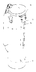
FIG. 1 shows a perspective view of a golf bag of the present
invention.
FIG. 2 shows a schematic view of a tilting structure of the golf
bag of the present invention.
FIG. 3 shows a partial exploded view of the adjustable rod
member of the tilting structure of the golf bag of the present
invention.
FIG. 4 shows a longitudinal sectional view of the adjustable rod
member of the tilting structure of the present invention at work.
FIG. 5 shows another longitudinal sectional view of the
adjustable rod member of the tilting structure of the present invention
at work.
FIG. 6 shows a sectional schematic view of the ball-and-socked
joint by which the bottom end of the fixed tube of the adjustable rod
member is connected with the bottom of the golf bag of the present
invention.
FIG. 7 shows a schematic view of the golf bag of the present
invention which is placed uprightly on the ground.
FIG. 8 shows a schematic view of the golf bag of the present
invention which is tilted on the ground.
2

CA 02376804 2002-03-15
DETAILED DESCRIPTION OF THE INVENTION
As shown in FIGS. 1-8, a golf bag embodied in the present
invention comprises a bag body 10 of a cylindrical construction, a
support rod 30, and a tilting structure which is formed of a bag top
edge 11, a bog bottom disk 12, one or two tilting rods 13, a link piece
14, and an adjustable rod member 20. The support rod 30 is disposed
in the interior of the bag body 10 such that the top end of the support
rod 30 is fastened with the bag top edge 11, and that the bottom end of
the support rod 30 is fastened which the bag bottom disk 12 of the bag
body 10.
The bag top 11 is provided with a fastening piece 15 attached
thereto. The tilting rods 13 are pivotally fastened at the top end with
the fastening piece 15. The tilting rods 13 are linked with the
adjustable rod member 20 by the link piece 14.
The adjustable rod member 20 is formed of a movable tube 21
and a fixed tube 22. The movable tube 21 is fastened at the top end
with the bag top edge 11 such that the bottom end of the movable tube
21 is slidably fitted into the top end of the fixed tube 22. The fixed
tube 22 is fastened at the bottom end with the bottom disk 12 of the
bag body 10. The preferred embodiment of the present invention is
provided with a ball-and-socket joint which is formed by a ball 228 of
the bottom end of the fixed tube 22 and a socket 128 of the bottom
disk 12, ad illustrated in FIG. 6. The ball-and-socket joint allows the
bottom end of the fixed tube 22 to move limitedly in any directional,
ad illustrated by the dotted lines in FIG. 6.
3

CA 02376804 2002-03-15
As shown in FIGS. 3-5, the adjustable rod member 20 further
comprises a plug 24 and a spring 25, which are fitted into the top end
of the fixed tube 22. The bottom end of the spring 25 is stopped by the
plug 24. The bottom end of the movable tube 21 is urged by the top
end of the spring 25. The bottom end of the movable tube 21 is
provided with two position confining holes 211, whereas the top end
of the fixed tube 22 is provided with two pin holes 222. The bottom
end of the movable tube 21 is received in the top end of the fixed tube
22 in conjunction with a pin 23 which is put through the pin holes 222
of the fixed tube 22 and the position confining holes 211 of the
movable tube 21. The position confining holes 211 of the movable
tube 21 have a predetermined length and extends in the longitudinal
direction of the movable tube 21. The bottom end of the movable tube
21 has a contact portion 212, which is urged by the top end of the
spring 25. The sliding range of the movable tube 21 in the fixed tube
22 is corresponding to the length of the position confining holes 211
of the movable tube 21.
The fixed tube 22 is provided with a retaining piece 221 fastened
therewith for retaining the link piece 14 which is used to link the fixed
tube 22 of the adjustable rod member 20 with the tilting rods 13.
When the bag body 10 is tilted by the tilting rods 13, the spring
25 is compressed by the bottom end of the movable tube 21, as shown
in FIG. 5. Accordingly, the bag body 10 can be tilted by an external
force exerting on the bag top edge 11, thereby causing the bottom end
of the movable tube 21 to slide further into the top end of the fixed
tube 22 such that the spring 25 is compressed by the contact portion

CA 02376804 2002-03-15
212 of the movable tube 21. As a result, the tilting rods 13 spread out
such that the bottom ends of the tilting rods 13 are rested on the
ground, so as to tilt the bag body 10 on the ground, as shown in FIG.
8.
It must be noted here that the two pin holes 222 of the fixed tube
22 are opposite in location to each other, and that the two position
confining holes 211 of the movable tube 21 are opposite in location to
each other.
r

Dessin représentatif
Une figure unique qui représente un dessin illustrant l'invention.
États administratifs

2024-08-01 : Dans le cadre de la transition vers les Brevets de nouvelle génération (BNG), la base de données sur les brevets canadiens (BDBC) contient désormais un Historique d'événement plus détaillé, qui reproduit le Journal des événements de notre nouvelle solution interne.

Veuillez noter que les événements débutant par « Inactive : » se réfèrent à des événements qui ne sont plus utilisés dans notre nouvelle solution interne.

Pour une meilleure compréhension de l'état de la demande ou brevet qui figure sur cette page, la rubrique Mise en garde , et les descriptions de Brevet , Historique d'événement , Taxes périodiques et Historique des paiements devraient être consultées.

Historique d'événement

Description Date
Inactive : CIB désactivée 2015-03-14
Inactive : CIB du SCB 2015-01-17
Inactive : Symbole CIB 1re pos de SCB 2015-01-17
Inactive : CIB expirée 2015-01-01
Inactive : CIB de MCD 2006-03-12
Le délai pour l'annulation est expiré 2005-03-15
Demande non rétablie avant l'échéance 2005-03-15
Réputée abandonnée - omission de répondre à un avis sur les taxes pour le maintien en état 2004-03-15
Demande publiée (accessible au public) 2003-09-15
Inactive : Page couverture publiée 2003-09-14
Inactive : CIB attribuée 2002-10-04
Inactive : CIB en 1re position 2002-06-14
Inactive : Certificat de dépôt - Sans RE (Anglais) 2002-04-18
Exigences de dépôt - jugé conforme 2002-04-18
Demande reçue - nationale ordinaire 2002-04-18

Historique d'abandonnement

Date d'abandonnement Raison Date de rétablissement
2004-03-15

Historique des taxes

Type de taxes Anniversaire Échéance Date payée
Taxe pour le dépôt - générale 2002-03-15
Titulaires au dossier

Les titulaires actuels et antérieures au dossier sont affichés en ordre alphabétique.

Titulaires actuels au dossier
WEN-CHIEN CHENG
Titulaires antérieures au dossier
S.O.
Les propriétaires antérieurs qui ne figurent pas dans la liste des « Propriétaires au dossier » apparaîtront dans d'autres documents au dossier.
Documents

Pour visionner les fichiers sélectionnés, entrer le code reCAPTCHA :


Pour visualiser une image, cliquer sur un lien dans la colonne description du document. Pour télécharger l'image (les images), cliquer l'une ou plusieurs cases à cocher dans la première colonne et ensuite cliquer sur le bouton "Télécharger sélection en format PDF (archive Zip)" ou le bouton "Télécharger sélection (en un fichier PDF fusionné)".

Liste des documents de brevet publiés et non publiés sur la BDBC .

Si vous avez des difficultés à accéder au contenu, veuillez communiquer avec le Centre de services à la clientèle au 1-866-997-1936, ou envoyer un courriel au Centre de service à la clientèle de l'OPIC.


Description du
Document 
Date
(aaaa-mm-jj) 
Nombre de pages   Taille de l'image (Ko) 
Dessin représentatif 2002-07-03 1 6
Abrégé 2002-03-14 1 21
Description 2002-03-14 5 181
Revendications 2002-03-14 2 72
Dessins 2002-03-14 7 68
Certificat de dépôt (anglais) 2002-04-17 1 164
Rappel de taxe de maintien due 2003-11-17 1 106
Courtoisie - Lettre d'abandon (taxe de maintien en état) 2004-05-09 1 175