Sélection de la langue

Search

Sommaire du brevet 2377562 

Énoncé de désistement de responsabilité concernant l'information provenant de tiers

Une partie des informations de ce site Web a été fournie par des sources externes. Le gouvernement du Canada n'assume aucune responsabilité concernant la précision, l'actualité ou la fiabilité des informations fournies par les sources externes. Les utilisateurs qui désirent employer cette information devraient consulter directement la source des informations. Le contenu fourni par les sources externes n'est pas assujetti aux exigences sur les langues officielles, la protection des renseignements personnels et l'accessibilité.

Disponibilité de l'Abrégé et des Revendications

L'apparition de différences dans le texte et l'image des Revendications et de l'Abrégé dépend du moment auquel le document est publié. Les textes des Revendications et de l'Abrégé sont affichés :

  • lorsque la demande peut être examinée par le public;
  • lorsque le brevet est émis (délivrance).
(12) Demande de brevet: (11) CA 2377562
(54) Titre français: DISPOSITIF DE COMMANDE AUTOMATIQUE DE RACCORDEMENT DE LIGNES POUR HAUTE TENSION ELECTRIQUE
(54) Titre anglais: A DEVICE FOR THE AUTOMATIC CONTROL OF JOINTS IN ELECTRICAL HIGH VOLTAGE LINES
Statut: Réputée abandonnée et au-delà du délai pour le rétablissement - en attente de la réponse à l’avis de communication rejetée
Données bibliographiques
Abrégés

Abrégé français

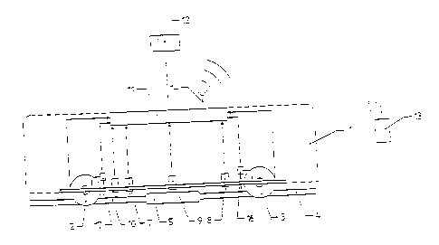
L'invention concerne un dispositif automatique de commande de raccordements (5) dans des lignes électriques à haute tension. Ce dispositif comprend un premier support (1) ; une première roue (2) destinée à être posée sur une ligne (4) ; un moyen d'entraînement permettant d'entraîner la première roue ; au moins une seconde roue (3) destinée à être posée sur la ligne (4) ; une unité de mesure (11) connectée à des moyens de mesure permettant la mesure de propriétés physiques audit raccordement. Ces moyens comprennent au moins un élément pointu (7, 8, 9) permettant le contact électrique avec la ligne (4). Le dispositif est spécialement caractérisé en ce qu'au moins une des roues (2, 3) est connectée électriquement à l'unité de mesure (11).


Abrégé anglais


A device for the automatic control of joints (5) in electrical high voltage
lines is disclosed. It comprises a first support (1), a first wheel (2) for
lying on a line (4), a driving means for driving of said first wheel (2), at
least one second wheel (3) for lying on said line (4), a measurement unit (11)
in contact with means for the measurement of physical data at said joint.
These means comprise at least one pointed element (7, 8, 9) for electrical
contact with the line (4). The device is especially characterized in that at
least one wheel (2, 3) is provided, electrically connected to said measurement
unit (11).

Revendications

Note : Les revendications sont présentées dans la langue officielle dans laquelle elles ont été soumises.


-5-
claims
A device for the automatic control of joints (5) in electrical high voltage
lines,
comprising a first support (1) a first wheel (2) for lying on a line (4), a
driving
means for driving of said first wheel (2), at least one second wheel (3) for
lying on
said line(4), a measurement unit (11) in contact with means for the
measurement of physical data at said joint, comprising at least one pointed
element (7,8,9) for electrical contact with the line (4),
characterized in that
at least one wheel (2,3) is provided, electrically connected to said
measurement
unit (11).
2.
A device according to claim 1,
characterized in that
at least two wheels (2,3) are electrically connected to said measurement unit
(11),
whereas a means for feeding current is provided to feed an electrical current
from the first wheel (2) to the second wheel (3) through the line (4).
3.
A device according to claim 1,
characterized in that
the means for measurement of physical data in the form of at least one pointed
element (7.8.9) also comprises at least one wheel (2,3).
4.
A device according to any of claims 1 to 3,
characterized in that
it comprises a holder- on (15), journalled in the support (1), intended to be
swung
up below the line (4) to increase the pressure of the wheel (2,3) against
same.
5.
A device according to any of claims 1 to 4,
characterized in that
measure position givers (16,17) preferably in the form of laser distance
gauges
are provided for measurement of the position of the device in relationship to
the
actual joint (5).

Description

Note : Les descriptions sont présentées dans la langue officielle dans laquelle elles ont été soumises.


CA 02377562 2001-12-14
WO 01/04651 PCT/SE00/01462
- 1 -
A device for the automatic control of joints in electrical high voltage
lines
The present invention relates to a device for the automatic control of joints
in
electrical high voltage lines, comprising a first support, a first wheel for
lying on
a line, a driving means for driving of said first wheel, at least one second
wheel
for lying on said line, a measurement unit in contact with means for the
measurement of physical data at said joint, comprising at least one pointed
element for electrical contact with the line.
Such devices are known, a g from the International Patent Application
PCT/SE93/00666, which discloses a device intended to be .located on a line for
electrical high voltage by a crane or a helicopter. This device comprises a
number
of means for remotely controlled, automatic measurement of physical data at a
joint in the line. The device shows, however, some limitations as to the
measurement methods, as only pointed elements are provided for electrical
measurements. There is a demand for a device of the art mentioned
introductorily, which enables more active measurement methods. According to
the invention, such a device is primarily characterized in that at least one
wheel
is provided, electrically connected to said measurement unit. In one
advantageous embodiment of the device at least two wheels are provided,
electrically connected to said measurement unit, whereas a means for feeding
current is provided to feed an electrical current from the first wheel to the
second wheel through the line. In one alternative embodiment of the device the
means for measurement of physical data in the form of at least one pointed
element (7,8,9) also comprise at least one wheel (2,3). In one advantageous
embodiment of the device it comprises a holder- on, journalled in the support,
intended to be swung up below the line to increase the pressure of the wheel
against same.
In the following the invention shall be described more in detail, reference
being
made to the three enclosed figures, of which:

CA 02377562 2001-12-14
WO 01/04651 PCT/SE00/01462
- 2 -
figure 1 schematically shows a view of one embodiment of the device according
to
the invention,
figure 2 shows a section of a wheel, provided with a glide contact, whilst
figure 3 schematically shows a view of part of the device, provided with a
swingable holder- on.
In figure 1 a schematically indicated support is denoted by 1, a first wheel
by 2, a
second wheel by 3 and a line, against which these wheels lie, by 4. At least
one of
these wheels is provided with a driving device, which is not shown. The line 4
is
provided with a joint 5. Both wheels are provided with a glide contact 6,
according to figure 2. The wheels are such designed, as to the outer diameter
D,
the inner diameter d, the outer width b, the inner free width e, the fillet
radius
r and the opening angle a,, that both the mechanical and electric demands are
fulfilled. The inclined inner sides of the wheel flanges are suitably provided
with
structured surfaces, a g in the form of groovings or other surface form, in
order
to warrant good electrical contact with the line, when the wheels are used for
feeding current, and also when they operate in the same way as the first,
second
and third pointed element, which are marked by 7,8 and 9. They are prestressed
by springs for lying with good electrical contact with the line 4 and the
joint 5. A
measurement pair of tongs 10 is provided for measurement of the amperage in
the line 4. The wheels via glide contacts, the pointed elements and the
measurement pair of tongs are all connected to an electric measurement unit
11,
which is also connected to an electric current feeding unit 12. The
measurement
unit 11 may be connected to a control station 13 via an optical fiber, an
electric
line or wireless via an antenna 14, as is indicated in figure 1. The pointed
elements are, as is mentioned, provided for electrical contact with the line
and
joint, respectively. They also measure the temperature and transfer data of
same
to the measurement unit 11. The wheels may be used as pointed elements as
well as for current feed. In figure 3 there is shown a holder- on, swingable
in
relationship to the support 1, which holder- on is provided to press the wheel
from below, when the wheel has come to lie at the line 4, to warrant
electrical
contact. The holder- on can also be used for transfer, together with wheel 2,
current to line and joint 4,5 in order to get better current distribution in
these.

CA 02377562 2001-12-14
WO 01/04651 _ 3 _ PCT/SE00/01462
The device is lifted to the actual line and shall first be positioned. For
positioning
of the device, including the joint, that shall be measured, and measuring the
diameter of the line and the joint respectively, position givers in the form
of
distance gauges, are used, preferably of the laser type. In figure 1 they are
marked by 16 and 17. Furthermore here one not shown rotational giver is used
for measurement of the rotation of the driving wheel or the driving wheels, i
a
traveled length on the line. Principally the positioning is carried out such,
that
one operator drives the device forward on the line towards the actual joint.
If,
according to figure 1, the device is driven to the right, the position giver
17 will
be used for indicating when the left limit of the joint is achieved. The
device is
backed, and the length traveled is indicated by the rotational giver. The
position
16 giver indicates when it has reached the right limit. By the aid of
indicated
data the device is driven such that the joint will lie centrally within the
device.
The device may now be used, after positioning on the line for electrical high
voltage, the joint of which shall be controlled, in different ways according
to the
followin g:
Alternative A
The measurement unit 11, wheel 2, line 4 with joint 5 and wheel 3 form a
current circuit, within which a current of a known amperage is made to
circulate.
The voltage drop between at least two measurement points, wheel 2, pointed
elements 7,8,9 and wheel 3 is measured, as well as the temperature at the
pointed element 7,8 and 9.
Alternative B
The same current circuit as in alternative A is arranged, and a current with
per
se not known amperage is made to circulate in same, and the amperage in line 4
is measured with the measurement pair of tongs 10. Otherwise the same
measurements are carried out as according to alternative A.
Alternative C
In this case the line 4 is fed with a current of known amperage. The voltage
drop
is measured between at least two of the measurement points, that are formed by
the two wheels via their glide contacts and the pointed elements 7,8 and 9.
Otherwise the measurements are carried out according to alternative A.

CA 02377562 2001-12-14
WO 01/04651 PCT/SE00/01462
- 4 -
Alternative D
The line 4 is here fed with a current of a not known amperage. This is
measured
by the measurement pair of tongs 10, and otherwise it is measured according to
alternative C.
Alternative E
In this case the line 4 is fed with a current of not known amperage. This is
measured by the measurement pair of tongs 10 and the voltage drop is measured
between a wheel via its glide contact and the pointed elements 7,8 and 9.
Furthermore the temperature is measured at the pointed elements 7,8 and 9.
Within the scope of the invention, the device may be formed in several ways.
Thus, the symmetry plane of the wheels, parallel to the line.4, must not lie
in the
same plane. The means for physical measurement may also include such ones for
the measurement in three dimensions of position in relationship to the line
and
the joint. The pointed elements may be placed above, at the side of or below
the
line 4, also outside of the wheels. The pointed elements may be arranged such,
that they admit the measurement of the form of the joint and bending,
respectively. Their pressure against the line 4 is, as is mentioned, suitably
adapted by springs. The device may of course be fitted with several different,
here not shown sensors, and may also be equipped for remote control or more
direct control, according to demand. The measurement pair of tongs may be
placed optionally within or outside of the wheels.

Dessin représentatif
Une figure unique qui représente un dessin illustrant l'invention.
États administratifs

2024-08-01 : Dans le cadre de la transition vers les Brevets de nouvelle génération (BNG), la base de données sur les brevets canadiens (BDBC) contient désormais un Historique d'événement plus détaillé, qui reproduit le Journal des événements de notre nouvelle solution interne.

Veuillez noter que les événements débutant par « Inactive : » se réfèrent à des événements qui ne sont plus utilisés dans notre nouvelle solution interne.

Pour une meilleure compréhension de l'état de la demande ou brevet qui figure sur cette page, la rubrique Mise en garde , et les descriptions de Brevet , Historique d'événement , Taxes périodiques et Historique des paiements devraient être consultées.

Historique d'événement

Description Date
Inactive : CIB expirée 2020-01-01
Demande non rétablie avant l'échéance 2010-07-08
Le délai pour l'annulation est expiré 2010-07-08
Réputée abandonnée - les conditions pour l'octroi - jugée non conforme 2009-09-28
Réputée abandonnée - omission de répondre à un avis sur les taxes pour le maintien en état 2009-07-08
Un avis d'acceptation est envoyé 2009-03-26
Lettre envoyée 2009-03-26
Un avis d'acceptation est envoyé 2009-03-26
Inactive : Approuvée aux fins d'acceptation (AFA) 2009-03-23
Modification reçue - modification volontaire 2008-03-26
Inactive : Dem. de l'examinateur par.30(2) Règles 2007-09-28
Inactive : CIB de MCD 2006-03-12
Lettre envoyée 2004-12-08
Exigences pour une requête d'examen - jugée conforme 2004-11-22
Toutes les exigences pour l'examen - jugée conforme 2004-11-22
Requête d'examen reçue 2004-11-22
Lettre envoyée 2002-12-12
Inactive : Transfert individuel 2002-11-04
Inactive : Page couverture publiée 2002-06-11
Inactive : Lettre de courtoisie - Preuve 2002-06-11
Inactive : Notice - Entrée phase nat. - Pas de RE 2002-06-05
Demande reçue - PCT 2002-04-23
Exigences pour l'entrée dans la phase nationale - jugée conforme 2001-12-14
Demande publiée (accessible au public) 2001-01-18

Historique d'abandonnement

Date d'abandonnement Raison Date de rétablissement
2009-09-28
2009-07-08

Taxes périodiques

Le dernier paiement a été reçu le 2008-07-04

Avis : Si le paiement en totalité n'a pas été reçu au plus tard à la date indiquée, une taxe supplémentaire peut être imposée, soit une des taxes suivantes :

  • taxe de rétablissement ;
  • taxe pour paiement en souffrance ; ou
  • taxe additionnelle pour le renversement d'une péremption réputée.

Les taxes sur les brevets sont ajustées au 1er janvier de chaque année. Les montants ci-dessus sont les montants actuels s'ils sont reçus au plus tard le 31 décembre de l'année en cours.
Veuillez vous référer à la page web des taxes sur les brevets de l'OPIC pour voir tous les montants actuels des taxes.

Historique des taxes

Type de taxes Anniversaire Échéance Date payée
Taxe nationale de base - générale 2001-12-14
TM (demande, 2e anniv.) - générale 02 2002-07-08 2001-12-14
Enregistrement d'un document 2002-11-04
TM (demande, 3e anniv.) - générale 03 2003-07-08 2003-07-04
TM (demande, 4e anniv.) - générale 04 2004-07-08 2004-06-18
Requête d'examen - générale 2004-11-22
TM (demande, 5e anniv.) - générale 05 2005-07-08 2005-04-28
TM (demande, 6e anniv.) - générale 06 2006-07-10 2006-05-01
TM (demande, 7e anniv.) - générale 07 2007-07-09 2007-05-11
TM (demande, 8e anniv.) - générale 08 2008-07-08 2008-07-04
Titulaires au dossier

Les titulaires actuels et antérieures au dossier sont affichés en ordre alphabétique.

Titulaires actuels au dossier
VATTENFALL AB
Titulaires antérieures au dossier
JONAS ORMIN
Les propriétaires antérieurs qui ne figurent pas dans la liste des « Propriétaires au dossier » apparaîtront dans d'autres documents au dossier.
Documents

Pour visionner les fichiers sélectionnés, entrer le code reCAPTCHA :


Pour visualiser une image, cliquer sur un lien dans la colonne description du document. Pour télécharger l'image (les images), cliquer l'une ou plusieurs cases à cocher dans la première colonne et ensuite cliquer sur le bouton "Télécharger sélection en format PDF (archive Zip)" ou le bouton "Télécharger sélection (en un fichier PDF fusionné)".

Liste des documents de brevet publiés et non publiés sur la BDBC .

Si vous avez des difficultés à accéder au contenu, veuillez communiquer avec le Centre de services à la clientèle au 1-866-997-1936, ou envoyer un courriel au Centre de service à la clientèle de l'OPIC.


Description du
Document 
Date
(aaaa-mm-jj) 
Nombre de pages   Taille de l'image (Ko) 
Dessin représentatif 2002-06-09 1 7
Revendications 2001-12-13 1 39
Abrégé 2001-12-13 1 46
Dessins 2001-12-13 1 16
Description 2001-12-13 4 205
Description 2008-03-25 5 215
Dessins 2008-03-25 2 20
Revendications 2008-03-25 1 36
Avis d'entree dans la phase nationale 2002-06-04 1 194
Courtoisie - Certificat d'enregistrement (document(s) connexe(s)) 2002-12-11 1 106
Accusé de réception de la requête d'examen 2004-12-07 1 177
Avis du commissaire - Demande jugée acceptable 2009-03-25 1 163
Courtoisie - Lettre d'abandon (taxe de maintien en état) 2009-09-01 1 172
Courtoisie - Lettre d'abandon (AA) 2009-12-20 1 164
PCT 2001-12-13 8 302
Correspondance 2002-06-04 1 24