Sélection de la langue

Search

Sommaire du brevet 2379248 

Énoncé de désistement de responsabilité concernant l'information provenant de tiers

Une partie des informations de ce site Web a été fournie par des sources externes. Le gouvernement du Canada n'assume aucune responsabilité concernant la précision, l'actualité ou la fiabilité des informations fournies par les sources externes. Les utilisateurs qui désirent employer cette information devraient consulter directement la source des informations. Le contenu fourni par les sources externes n'est pas assujetti aux exigences sur les langues officielles, la protection des renseignements personnels et l'accessibilité.

Disponibilité de l'Abrégé et des Revendications

L'apparition de différences dans le texte et l'image des Revendications et de l'Abrégé dépend du moment auquel le document est publié. Les textes des Revendications et de l'Abrégé sont affichés :

  • lorsque la demande peut être examinée par le public;
  • lorsque le brevet est émis (délivrance).
(12) Demande de brevet: (11) CA 2379248
(54) Titre français: FLOTTEUR DE LIGNE TOUEE
(54) Titre anglais: TOWED LINE FLOATER
Statut: Réputée abandonnée et au-delà du délai pour le rétablissement - en attente de la réponse à l’avis de communication rejetée
Données bibliographiques
(51) Classification internationale des brevets (CIB):
  • B63B 21/66 (2006.01)
  • B63G 08/42 (2006.01)
(72) Inventeurs :
  • HOCQUET, PHILIPPE (Norvège)
  • BOUDET, LOIC PIERRE (France)
(73) Titulaires :
  • GECO AS
(71) Demandeurs :
  • GECO AS (Norvège)
(74) Agent: SMART & BIGGAR LP
(74) Co-agent:
(45) Délivré:
(86) Date de dépôt PCT: 2000-07-13
(87) Mise à la disponibilité du public: 2001-01-25
Licence disponible: S.O.
Cédé au domaine public: S.O.
(25) Langue des documents déposés: Anglais

Traité de coopération en matière de brevets (PCT): Oui
(86) Numéro de la demande PCT: PCT/FR2000/002030
(87) Numéro de publication internationale PCT: FR2000002030
(85) Entrée nationale: 2002-01-14

(30) Données de priorité de la demande:
Numéro de la demande Pays / territoire Date
99/09249 (France) 1999-07-16

Abrégés

Abrégé français

Ce flotteur comprend un fuseau (6) analogue à des flotteurs classiques, mais qui est ici surmonté par une jambe (7) de sorte que le fuseau (6) est entièrement immergé. Cette disposition, combinée à d'autres qui sont secondaires, permet de diminuer les oscillations verticales du flotteur que la houle produit tout en lui assurant une bonne tenue de route et une stabilité convenable aux autres perturbations. Ainsi, une structure (1) suspendue au flotteur (5) et qui fait partie d'une ligne (2, 3) touée par un navire reste à une profondeur constante. Cette invention s'applique par exemple aux essais sismiques en mer.


Abrégé anglais


The invention concerns a floater comprising a pod (6) similar to standard
floaters, but in this particular case with a strut (7) mounted thereon such
that the pod is entirely submerged. Such an arrangement, combined with other
secondary ones, enables to reduce vertical oscillations of the floater caused
by the swell while providing it with suitable stability towards other
perturbations. Thus, a structure (1) suspended to the floater (5) and forming
part of a line (2, 3) towed by a ship remains at a constant depth. The
invention is applicable, for instance, to seismic tests at sea.

Revendications

Note : Les revendications sont présentées dans la langue officielle dans laquelle elles ont été soumises.


CLAIMS
1. Float (5) for a towed line, comprising a
horizontal portion (6) with a fuselage shape,
characterised in that it comprises an upper
portion (7), extending upwards from the horizontal
portion and in that the horizontal portion is
completely submerged, and the upper portion is partly
emerged, when the float supports an element (1) of the
line.
2. Float according to claim l, characterised in
that the upper portion (7) rises at the rear of the
horizontal portion (6).
3. Float according to claim 2, characterised in
that a suspension element (19) of a portion (1) of the
line, located under the horizontal portion, is also set
in front of at least the greater part of the upper
portion (7).
4. Float according to claim 3, characterised in
that the suspension element (19) comprises a single
articulation (25), which has a transversal axis.
5. Float according to any one of claims 1 to 4,
characterised in that the horizontal portion (6) is
wider than it is high.

8
6. Float according to claim 5, characterised in
that the horizontal portion has a base (12) and an
upper deck (16), both partially flat.
7. Float according to claim 6, characterised in
that the horizontal portion has closely rectangular
cross-sections.
8. Float according to any one of claims 5 to 7,
characterised in that it comprises a base with a rising
step (13) at the rear, vertical fins (14) being housed
in the step.
9. Float according to any one of claims 1 to 8,
characterised in that it comprises horizontal fins (15)
on the horizontal portion (6).
10. Float according to any one of claims 1 to 9,
characterised in that the upper portion (7) has
substantially uniform horizontal cross-sections.

Description

Note : Les descriptions sont présentées dans la langue officielle dans laquelle elles ont été soumises.

CA 02379248 2002-O1-14
1
TOWED LINE FLOATER
The present invention relates to a float for a
towed line, whose field of application is generally
seismic measurements at sea, in which a battery of
lines carrying acoustic sensors is towed at the stern
of a ship. Each of the lines comprises a deflector in
front of the sensors, which is a submerged and vertical
wing which incurs a transversal lift and maintains the
line alongside the wake of the ship, and a float _re~«
which the deflector is suspended and whose aim is t:,
prevent the line from sinking under the weight of the
deflector.
The floats must be almost insensitive to the
disturbances to which they may be submitted, in
particular by the sea swell. Unfortunately, as far as
this is concerned, ti:e knowr_ floats oscillate too
easily in the vertical direction follow_ng the
movements of the swell. The suspension line of the
float deflector is submitted to periodic surges which
can end by fatigue rupture or car, create damage to the
connections, and the quality of measurement can also be
disturbed. The float to be described below overcomes
this disadvantage while still retaining good
directional stability, above all in its most
advantageous embodiment.
The known floats have a fuselage shape, expanded
in the centre and progressively tapered towards the
ends. The float according to the invention comprises a
horizontal portion of:the floating body whose shape is
also substantially fuselage shaped, but also an upper
SP 16998 JCI

" ~ CA 02379248 2002-O1-14
2
part of the floating body, extending from the
horizontal portion upwards and with horizontal cross-
sections which are closely uniform; in addition, the
horizontal portion is completely submerged and the
upper portion is partially emerged when the float holds
the line, or a heavy element of the latter.
The vertical movement of the sea swell is
therefore represented above all by a variation of the
immersion of the upper portion without any special
force on the float because of the uniformity of its
cross-section and the small variation of the submerged
volume: the vertical oscillating movement of the float
and its load therefore does not have a great amplitude.
The stability is still better if the upper portion
is higher at the rear of the horizontal portion, and
particularly if the suspension element of the deflector
is located in front of the upper portion.
If this suspension element comprises a single
articulation around a transversal axis, the float is
restrained from rolling movements and comes back into
place more easily.
The directional stability of the float is improved
if its horizontal portv~on is wider than its height,
which makes it possible to reduce its lateral surface,
and thus the lateral disturbing forces.
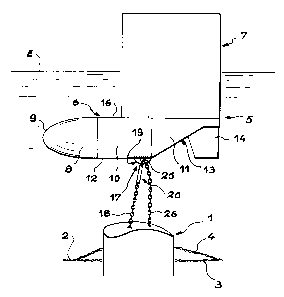
The invention will now be described with the aid
of the figures below, showing one embodiment:
- figure 1 is a side view of the float,
- figure 2 is a view from above the float,
- figure 3 is a cross-section of the float along
the line III-III.
SP 16998 JCI

CA 02379248 2002-O1-14
3
A part of the line towed for seismic measurements
is shown in figure 1. It comprises, on either side of a
submerged deflector 1, a front portion of line 2
attached to a ship located on the left and a rear
portion of line 3 to which the sensors are attached
located on the right (outside the figure). In addition,
a line deviation 4 links the fore and aft portions 2
and 3 avoiding the deflector l, and serves for
transmitting the signal from the sensors to the ship.
The deflector 1 is maintained at a closely constant
depth thanks to a float 5, characteristic of the
invention, preventing it from sinking lower, whether it
is suspended by a cable or by a chain 18.
The float 5 comprises a horizontal and lower
portion of a floating body here called a fuselage 6 and
an upper vertical portion of a floating body called a
leg 7. The fuselage 6 has: a front portion 8 intended
to promote penetration in the water and which is
therefore tapered towards the front, as far as a
rounded end 9; a median portion 10 of closely uniform
cross-section; and a rear portion 11 reducing towards
the rear, a base surface 12 of the fuselage 6 at this
point having a rising step 13 to recede upwards and to
form a concave housing for a vertical fin 14; other
fins, horizontal, 15, are placed on the sides of the
fuselage 6. The horizontal fins 15 are a disadvantage
in that they increase the transversal dimensions of the
float 5, but they can be made detachable or retractable
to make them disappear when the float 5 is on board the
ship. It is advantageous for the cross-sections of the
fuselage 6 to be closely rectangular and for its faces
SP 16998 JCI

CA 02379248 2002-O1-14
4
to be defined by the edges 24 forming almost sharp
edges as shown in figure 3. Preferably, the base 12 is
flat over the greater part of its length, particularly
in the median part 10, and the upper surface of the
fuselage 6 forms an upper flat deck 16 between the
median part 10 and the rear part 11.
Advantageously, the leg 7 is at the back of the
fuselage 6 and extends substantially over half of its
length, substantially over the whole of the rear
part 11 and over half of the median part 10. A
suspension element 17 of the deflector 1 by the
chain 18 is attached to the base 12, and comprises a
coupling 19 fixed to the fuselage 6, a connecting
rod 20 connected to the chain 18 and a transversal axis
articulation 25 between them, which thus makes it
possible for the conr_ecting rod 20 to oscillate
backwards and forwards bat not laterally, such that the
deflector 1 helps to stabilise the float 5 against
rolling movements by restraining its rotation around
the longitudinal axis. A safety chain 26 could further
unite the deflector 1 to the coupling 19 and support it
if the suspension element 17 were to break. The
connecting rod 20 can include a shock absorber.
The leg 7 is substantially half-submerged under
the surface of the water E and comprises a front
portion 21 rounded as a half-cylinder to promote
penetration, and a rear portion 22 formed of two
surfaces joined together at an edge 23 located at the
rear. The leg 7 is smooth, with substantially identical
cross-sections, in order to limit the forces produced
by the vertical movements of the sea swell.
SP 16998 JCI

CA 02379248 2002-O1-14
The mechanical principle sought consists generally
of making the actual frequency of heaving (vertical
oscillatory movement) of the float 5 close to a value
where the movements of the swell only exert a minimum
5 force, which attenuates the forces on the suspension
element 17. The dimensions of the fuselage 6 and the
cross-section of the leg 7 can be chosen in
consequence, as a function of the results of digital
simulations or pool trials. However, it was noted that
a positive result was more easily obtained if the
base 12 and the deck 16 were flat and relatively close
to each other, which justifies the fuselage being wider
than it is high. One also tries to increase the
friction produced by the vertical movement of the water
in order to damp down the oscillation of the float 5;
the almost sharp angles of the edges 24 of the
fuselage 6, as well as the horizontal fins 15, provide
this result by creating eddies.
Other considerations concern the stabilisation of
the forward movement of the float 5. It is normal to
improve it by providing the floats with appendages,
which can however increase the towing force and to
elongate them towards the rear. Such appendages are not
needed here, where the leg 7 works as a rudder, the
vertical fin 14 having the same effect if it is added.
The leg 7 is best set behind the fuselage 6, and the
coupling 19 also as far to the front as possible so
that it does not upset the balance of the float 5, in
front of the leg 7 or at least the greater part of it.
The centre of the hull of the float 5 must be brought
forward and its centre of gravity moved backward. The
SP 16998 JCI

CA 02379248 2002-O1-14
6
flattening of the fuselage 6 and the reduction of its
resulting lateral surface is also positive concerning
this, since the lateral disturbances produced by the
water will be reduced.
In general, it is preferable not to place ballast
in the float 5, which could make it more stable but
which would increase its mass and its displacement.
SP 16998 JCI

Dessin représentatif
Une figure unique qui représente un dessin illustrant l'invention.
États administratifs

2024-08-01 : Dans le cadre de la transition vers les Brevets de nouvelle génération (BNG), la base de données sur les brevets canadiens (BDBC) contient désormais un Historique d'événement plus détaillé, qui reproduit le Journal des événements de notre nouvelle solution interne.

Veuillez noter que les événements débutant par « Inactive : » se réfèrent à des événements qui ne sont plus utilisés dans notre nouvelle solution interne.

Pour une meilleure compréhension de l'état de la demande ou brevet qui figure sur cette page, la rubrique Mise en garde , et les descriptions de Brevet , Historique d'événement , Taxes périodiques et Historique des paiements devraient être consultées.

Historique d'événement

Description Date
Demande non rétablie avant l'échéance 2005-07-13
Le délai pour l'annulation est expiré 2005-07-13
Réputée abandonnée - omission de répondre à un avis sur les taxes pour le maintien en état 2004-07-13
Lettre envoyée 2003-01-13
Inactive : Transfert individuel 2002-11-12
Inactive : Page couverture publiée 2002-07-10
Inactive : Lettre de courtoisie - Preuve 2002-07-09
Inactive : Notice - Entrée phase nat. - Pas de RE 2002-07-05
Demande reçue - PCT 2002-05-03
Exigences pour l'entrée dans la phase nationale - jugée conforme 2002-01-14
Demande publiée (accessible au public) 2001-01-25

Historique d'abandonnement

Date d'abandonnement Raison Date de rétablissement
2004-07-13

Taxes périodiques

Le dernier paiement a été reçu le 2003-06-25

Avis : Si le paiement en totalité n'a pas été reçu au plus tard à la date indiquée, une taxe supplémentaire peut être imposée, soit une des taxes suivantes :

  • taxe de rétablissement ;
  • taxe pour paiement en souffrance ; ou
  • taxe additionnelle pour le renversement d'une péremption réputée.

Les taxes sur les brevets sont ajustées au 1er janvier de chaque année. Les montants ci-dessus sont les montants actuels s'ils sont reçus au plus tard le 31 décembre de l'année en cours.
Veuillez vous référer à la page web des taxes sur les brevets de l'OPIC pour voir tous les montants actuels des taxes.

Historique des taxes

Type de taxes Anniversaire Échéance Date payée
Taxe nationale de base - générale 2002-01-14
TM (demande, 2e anniv.) - générale 02 2002-07-15 2002-06-05
Enregistrement d'un document 2002-11-12
TM (demande, 3e anniv.) - générale 03 2003-07-14 2003-06-25
Titulaires au dossier

Les titulaires actuels et antérieures au dossier sont affichés en ordre alphabétique.

Titulaires actuels au dossier
GECO AS
Titulaires antérieures au dossier
LOIC PIERRE BOUDET
PHILIPPE HOCQUET
Les propriétaires antérieurs qui ne figurent pas dans la liste des « Propriétaires au dossier » apparaîtront dans d'autres documents au dossier.
Documents

Pour visionner les fichiers sélectionnés, entrer le code reCAPTCHA :


Pour visualiser une image, cliquer sur un lien dans la colonne description du document. Pour télécharger l'image (les images), cliquer l'une ou plusieurs cases à cocher dans la première colonne et ensuite cliquer sur le bouton "Télécharger sélection en format PDF (archive Zip)" ou le bouton "Télécharger sélection (en un fichier PDF fusionné)".

Liste des documents de brevet publiés et non publiés sur la BDBC .

Si vous avez des difficultés à accéder au contenu, veuillez communiquer avec le Centre de services à la clientèle au 1-866-997-1936, ou envoyer un courriel au Centre de service à la clientèle de l'OPIC.


Description du
Document 
Date
(aaaa-mm-jj) 
Nombre de pages   Taille de l'image (Ko) 
Dessin représentatif 2002-07-08 1 6
Revendications 2002-01-13 2 51
Description 2002-01-13 6 214
Abrégé 2002-01-13 1 15
Dessins 2002-01-13 1 19
Rappel de taxe de maintien due 2002-07-07 1 114
Avis d'entree dans la phase nationale 2002-07-04 1 208
Courtoisie - Certificat d'enregistrement (document(s) connexe(s)) 2003-01-12 1 107
Courtoisie - Lettre d'abandon (taxe de maintien en état) 2004-09-06 1 178
Rappel - requête d'examen 2005-03-14 1 117
PCT 2002-01-13 15 574
Correspondance 2002-07-04 1 23
Taxes 2003-06-24 1 34
Taxes 2002-06-04 1 49