Note : Les descriptions sont présentées dans la langue officielle dans laquelle elles ont été soumises.
CA 02379337 2002-O1-14
- 1 -
TITLE
CIRCULAR OR ANNULAR COATING FILM FORMING METHOD
TECHNICAL FIELD
The present invention relates to a method of
forming a circular or an annular coating film on a
substrate.
BACKGROUND OF THE INVENTION
Conventionally, coating methods by spin coater
have been known, for example, as a method of applying
resist liquid in a generally circular shape to a generally
circular wafer. However, according to this method, most of
the coating liquid (about 95~) would not be recycled but
thrown away, resulting in a very poor yield.
Furthermore, a coating method by die coater has
been proposed in Japanese Patent Laid-Open Publication
No.lO-99764, in which resist liquid is applied in a
circular shape to a wafer, by providing a shim (choke
plate) within a slit of a die main body, the shim being
advanceable and retreatable along the longitudinal
direction of the slit, and by continuously advancing and
retreating the shim during the coating process while
traveling the die main body or the wafer (substrate)
horizontally.
In this method, in order to prevent. the coating
liquid from leaking through between the shim and the slit,
CA 02379337 2002-O1-14
- 2 -
the shim has to be held within the slit so as t.o be movable
with precision and smoothness. Accordingly, when the shim
arid the slit are manufactured and provided, not only quite
a high level of precision is required, but a:Lso the shim
has to be exchanged frequently due to heavy wear.
Moreover, in this method, since the movement of the shim
results in nonuniformity of the supply pressure in the
widthwise direction within the slit, uniform film thickness
of the coating film in the widthwise direction can not be
obtained.
Therefore, in recent years, a method is proposed
in which a length of a slit of the die main body is made
equal to a radius of the wafer such that coating liquid is
applied without waste by positioning opposite ends of the
slit at a center and an edge of the wafer, :respectively.
In this method, however, since an overlap portion of the
slit is formed at the center of the wafer, involving an
increased thickness of a coating film thickness at this
overlap. portion, there is a problem that a.coating film of
uniform thickness cannot be obtained.
Furthermore, in the foregoing coating method,
there is a problem that an annular coating film cannot be
formed.
CA 02379337 2002-O1-14
- 3 -
SUNll~IARY OF THE INVENTION
The present invention having been accomplished
with a view to eliminating these and other problems, an
object of the invention is to provide a method of forming a
circular or an annular coating film which makes it possible
to obtain uniform film thickness by equipment of simple
construction without wasting the coating fluid.
In order to achieve the above object, in the
present invention, by using a coating apparatus constructed
by a rotatable table on which a substrate is held
horizontally through evacuation and, a nozzle which is
movable vertically and horizontally above .the table and.
provided, at its distal end portion, with a discharge hole,
in which a coating liquid is supplied linearly from the
discharge hole to the substrate by moving the :nozzle in one
direction in a predetermined interval between a rotational
center of the table and a predetermined outer :position in a
state where the table is rotated and the nozzle is held at
a predetermined height from the rotating table.
According to the present invention, a circular or
an annular coating film can be formed only by linearly
moving the nozzle relative to the rotating substrate
without providing any complex mechanisms in the coating
apparatus and irrespectively of the substrate
configuration. Additionally, according to the invention,
CA 02379337 2002-O1-14
- 4 -
there can be produced effects such as elimination of
wasteful use of the coating liquid.
BRIEF DESCRIPTION OF THE DRAWINGS
Fig. 1 is a plan view of a coating apparatus used
for the present invention;
Fig. 2 is a sectional view taken a:Long the line
II - II of Fig. 1;
Fig. 3 is a view taken along the line III - III
direction in Fig. 2; and
Fig. 4 is a side view showing a move of the
nozzle of the coating apparatus.
DETAILED DESCRIPTION OF THE PREFERRED EMBODIMENTS
An embodiment of the present invention is
described below with reference to the accompanying
drawings.
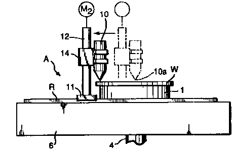
The drawings show a coating apparatus A for
performing the present invention.
As shown in Fig. 1, this coating apparatus A is
composed roughly of a table 1 and a nozzle 10: As shown in
Fig. 2, the table 1 is fixed to one end of a hollow shaft 4
penetrating a base 6, and held by a bearing ~ provided at
the penetrating portion of the base 6 so as to be rotatable
together with the hollow shaft 4. The other end of the
hollow shaft 4 is connected to an unshown vacuum pump via a
rotary joint 7. A gear 8 is provided at a protruding
CA 02379337 2002-O1-14
- 5 -
portion of the hollow shaft 4 on the lower face' side of the
base 6, such that the table 1 is rotated by dz~iving a gear
9 engaging with the gear 8 by a motor Ml.
The table 1 has a surface of a predetermined
flatness, for example, a flatness of 2 ~.im or :Less. Inside
the table 1, headers 2 are provided radial.ly so as to
communicate with a space 4a in the hollow sh,3ft 4, and a
multiplicity of evacuating holes 3 are provided so as to
penetrate from each of the headers 2 to the surface of the
table 1. Therefore, camber and undulation of <~ substrate W
can be corrected by driving the vacuum pump so that the
substrate W is held .through evacuating on the surface of
the table 1.
As shown in Figs. 1 and 2, a pedestal 11 moving
to and fro by an unshown mechanism for horizontal transfer
is mounted on two rails R which are disposed at opposite
sides of a width of the base 6 so as to confront each other
through the table 1. Further, a beam 14 is provided on the
pedestal 11 through lifters 13 supporting both end portions
of the beam 14, each lifter 13 being composed of a stepping
motor MZ and a non-backlash ball screw 12. The nozzle 10
is held at a predetermined position of the beam 14, that
is, such a position in which a discharge hole 10a of the
nozzle 10 passes through the rotational center of the table
1 when the pedestal 11 moves to and fro.
CA 02379337 2002-O1-14
- 6 -
As a result, it becomes possible for the
discharge hole 10a of the nozzle 10 to move to and fro
maintaining at a predetermined height from the surface of
the table 1 along one direction between thES rotational
center of the table 1 and the predetermined outer position
on the substrate W.
Meanwhile, as shown in Fig. 3, the discharge hole
10a of the nozzle 10 is formed so as to supply the coating
liquid linearly to the substrate W, which is held on the
table 1 through evacuating.
Then, a method for using the coating apparatus A
having the above structure is. described.
Firstly, the pedestal 11 is transferred by the
unshown mechanism for horizontal transfer :~o that the
nozzle 10 is positioned on one end portion of the base 6 as
shown in Fig. 1. Thereafter, the substrate W, which is a
wafer for example, is disposed on the table 1, and by
driving the vacuum pump, the substrate W is held onto the
table 1 through evacuating.
Further, while the table 1 is rotate~~ by driving
the motor Ml, the pedestal 11 is moved by the mechanism for
the horizontal transfer so that the discharge hole 10a of
the nozzle 10 is positioned above the rotational center of
the table 1 as shown by two-dot chain line in Fig. 4.
CA 02379337 2002-O1-14
7
Subsequently, by driving the stepping motors MZ,
MZ, the nozzle 10 is moved downward so that the distal end
of the nozzle 10 and the surface of the viable l are
adjusted so as to be spaced from each other by a
predetermined distance (reference gap).
Thereafter, by driving an unshown device for
supplying coating liquid to supply the coating liquid to
the nozzle 10, coating process is started. Thus, while
coating is performed, the pedestal 11 (nozzle 10) is moved
to a predetermined outer position on the sut~strate W as
shown in Fig. 4.
In his case, the nozzle 10 is, basically, moved
by the same distance as the width of the discharge hole 10a
of the nozzle 10 (i.e., the width of discharged coating
liquid) during one rotation of the table 1. However, the
nozzle 10 may be moved by a distance larger than the width
of the discharge hole 10a (i.e., the width of discharged
coating liquid) depending on the properties of the coating
liquid.
For example, leveling property is described here
in properties of the coating liquid. When a coating liquid
of poor leveling property is applied, the coating liquid is
less likely to diffuse on the substrate surfa~~e, in which
case it is advisable that the nozzle 10 is moved by the
same distance as the width of the discharge hole 10a during
CA 02379337 2002-O1-14
one rotation of the table 1 so that a side face of the
linear coating liquid supplied from the discharge hole 10a
makes into contact with a side face of a coating film
formed by the preceding rotation. In contrast to this,
when a coating liquid of good leveling propert~~r is applied,
the coating liquid is more likely to diffuse on the
substrate surface, in which case it is advisable that the
table 1 is moved by a distance larger than the width of the
discharge hole 10a during one rotation of the table 1 so
that a gap is formed between a side face of the coating
film formed by the preceding rotation and a side face of
the linear coating liquid supplied from the d~_scharge hole
10a.
Meanwhile, the leveling property of coating
liquid means the fluidity of the coating liquid itself.
Therefore, in the case of good leveling pro~~erty of the
coating liquid, when a predetermined time elapsed after the
coating on the substrate, the formed coating film is
diffused uniformly on the substrate surface by the fluidity
of the coating liquid itself, resulting in a successful
coating state free from streaks and nonuniformities. Thus,
generally, the lower the viscosity of a coatin<~ liquid, the
higher the leveling property of the coating liquid.
However, even though the viscosity of the coat~_ng liquid is
low, for example, if the coating liquid using a solvent
CA 02379337 2002-O1-14
_ g _
having a very high volatility is applied to the substrate,
it may occur that the solvent volatilizes and dries before
the coating film is diffused uniformly on the substrate
surface by the fluidity of the coating liquid itself,
thereby resulting in streaks, nonuniformities or the like.
Such coating liquids are not good regarding leveling
property in spite of low viscosity.
That is, since the substrate W is rotating, the
linear coating fluid flows down from the discharge hole 10a
as if it were flowing along a groove on a phonograph record
surface, so that a coating film of circular shape and
uniform_thickness.is formed ori.the substrate W by virtue of
the centrifugal force based on the rotation of the
substrate W and the leveling property of the coating
liquid.
Then, after the nozzle 10 is moved horizontally
through a distance equal to a radius of a desired circular
coating film, the supply of the coating liquid is stopped
and besides the rotation of the table 1 is stopped.
Subsequently, the stepping motors M2, MZ are rotated such
that the nozzle 10 is lifted up to a ~~redetermined
position, and further the horizontal transfer mechanism is
driven such that the nozzle 10 is retreated to a
predetermined position of the base 6, thus the nozzle 10 is
set on standby for the succeeding step (see Fi~~. 1).
CA 02379337 2002-O1-14
-10-
A circular coating film is form~ad on the
substrate W by following the above steps, thereafter the
vacuum pump is stopped and the substrate W is transferred
to the succeeding process by an unshown means. Then, the
next substrate W is disposed on the table 1, and the
foregoing coating process is repeated again.
In the above description, the substrate W has
been assumed to be a circular wafer. However, the
substrate W is not limited to wafers, and the substrate
configuration is not limited to circular shape, either.
Furthermore, the cross-sectional configuration of the
discharge hole 10a may. be either circular or rectangular.
shape.
Furthermore, in the above description,, the nozzle
10 has been moved linearly from the rotational center of
the table 1 toward an outer position on the :substrate W.
Conversely, the nozzle 10 may also be moved from a
predetermined outer position on the substrate ~a toward the
rotational center.
In the foregoing coating process, as the position
of the nozzle 10 moves outward from the center ~~f the table
1 to an outer position on the substrate W or moves inward
from the outer position to center position, the substrate W
under the discharge hole 10a varies in peripheral speed.
Therefore, the supply amount of the coating 1~_quid may be
CA 02379337 2002-O1-14
-11-
gradually increased or decreased in accordance with this
variation in peripheral speed. Further, the peripheral
speed at coating positions may be maintained constant at
all times by varying the rotating speed of the table 1.
Meanwhile, the above-described configuration of
the coating film is a circular shape. However, an annular
coating film can be formed by supplying the coating liquid
in a linear state onto the substrate from the discharge
hole while the nozzle 10 is moved through a predetermined
interval between the rotational center of the gable 1 and a
predetermined outer position on the substrate in one
direction. Moreover, striped-pattern coating films can
also be formed by forming annular coating films at any
arbitrary intervals on the same substrate.
Example:
As a result of applying the method according to
the present invention under the following c~~nditions, a
satisfactory coating film having a film thickness of 10 ~.un
was formed:
(1) Substrate:
Diameter: 200 mm
Rotating speed: 60 rpm
(2) Nozzle:
Inner diameter: 1.0 mm
Moving speed: 1.0 mm/sec.
CA 02379337 2002-O1-14
-12-
Moving direction: toward center of substrate
Moving range: from position of diameter 192 mm of
substrate to substrate center ( diameter 0 mm )
Gap: 60 ~.un (distance between substrate and distal end
of nozzle)
Discharge amount: 100 at coating start position
0~ at coating end position
(3) coating liquid
Viscosity: 10 p (1000 cp)