Note : Les descriptions sont présentées dans la langue officielle dans laquelle elles ont été soumises.
CA 02379517 2002-O1-15
WO 01/18422 PCT/US00/22666
CAM SHAFT SUPPORT AND ENCLOSURE ASSEMBLY
BACKGROUND OF THE INVENTION
FIELD OF THE INVENTION
The invention relates to brake systems of heavy duty vehicles, and
in particular to cam assemblies of the brake system. More particularly,
the invention is directed to a cam shaft enclosure/support assembly which
enables efficient installation of the cam assembly on various types of
axle/suspension systems, and extends the life of the cam assembly.
BACKGROUND ART
In conventional heavy duty vehicle brake systems, an S-cam is
utilized to lift brake shoes against a brake drum to decelerate a vehicle.
The cam shaft to which the S-cam is integrally connected typically is
supported at each of its ends by a bushing or bearing. These bushings
usually are greased to reduce friction between the bushings and the cam
shaft.
If the bushings or the cam shaft become worn and/or rotational
friction of the cam shaft against the bushings increases, the overall
efficiency of the brake system decreases. Of course, when bushing or
cam shaft wear exceeds predetermined limits, bushing and/or cam shaft
replacement is required. Recommended practice in the industry is that
when the cam shaft and/or bushings on one end of an axle require
replacement, then the cam shaft and/or bushings on the other end of the
same axle should also be replaced, and all other axles of the vehicle
should be inspected for the same worn condition.
There are two primary contributors to cam shaft and bushing wear,
namely, load-induced wear and contamination-induced wear. Wear due
to loading is encountered in two different conditions that can be defined
CA 02379517 2002-O1-15
WO 01/18422 PCT/US00/22666
-2-
as quasi-static and dynamic. The quasi-static case occurs when the
vehicle brakes are applied and braking forces are reacted in the cam shaft
bushings. This scenario is considered quasi-static due to the relatively
low rotational speed of the cam shaft and the steady state condition when
the brakes are held at constant pressure. In such a case, the loads on
the outboard bushing are greater than on the inboard bushing. The
dynamic load case typically occurs when the brakes are in the released
condition and the cam shaft experiences vibrations due to road inputs.
These vibrations result in impact loading of the cam shaft against the
bushings.
Cam shaft and bushing wear due to contamination is caused
primarily by environmental factors. Seals generally are disposed on each
end of each bushing to capture the lubricant inside the bushings as well
as to prevent ingress of contaminants from the outside environment. The
lubricant not only acts to reduce friction between the cam shaft and the
bushings, but also suspends any contaminants that may migrate past the
seals and into the bushing. The lubricant also acts as a barrier to
moisture that could cause corrosion of the cam shaft.
Thus, various types of cam shaft enclosure and/or support
assemblies have been utilized in the brake system art to protect and
support the cam shaft and ensure coaxiality of the bushings to prevent
excessive rotational friction or binding of the cam shaft against one or
more of the bushings when the brakes are actuated. Maintaining
coaxiality of the bushings also improves the load support of the bushings.
More particularly, loads are more evenly distributed across the surfaces of
both bushings and there is a reduced chance of the cam shaft contacting
a small area or edge of one of the bushings. Such support increases the
load-bearing area available for the cam shaft, thus reducing bushing wear
due to quasi-static and dynamic load conditions. Such a cam
support/enclosure assembly also protects the bushings from
environmental contamination. The cam tube eliminates two seals over
CA 02379517 2002-O1-15
WO 01/18422 PCT/US00/22666
-3-
bushings used without a cam tube, and reduces by two the number of
locations for ingress of contaminants into the bushings. The cam tube
also provides a larger grease reservoir to improve lubricity and to suspend
any contaminants that may migrate past the seals.
However, prior art cam shaft support/enclosure assemblies
typically have required a weld at the attachment point of the inboard end
of the cam tube to the vehicle to react rotation of the tube induced by cam
shaft rotation. Unfortunately, such a weld can be subject to fatigue and
failure. Moreover, due to the requirement of such -welding and/or
shimming during installation of the cam tube support/enclosure assembly
during production of an axle/suspension system, the cam assembly
typically must be custom fit to a single type of axle/suspension system.
More specifically, different axle/suspension systems have different
distances between the two major support points for the cam assembly,
namely, the brake system spider and the beam of the axle/suspension
system. Thus, one size of cam assembly with fixed weld points will fail to
fit many axle/suspension systems. In addition, custom-fitting also is
required on same-type axle/suspension systems due to small tolerances
in the distance between the support points for the cam tube caused by
natural variations in manufacturing processes.
The present invention solves the above-described problems of
fatigue failure and custom-fitting by utilizing an inboard cam tube support
plate having a predetermined keyhole configuration that matches the
configuration of the periphery of the inboard end of the cam tube. The
support plate reacts cam tube rotation without the possibility of fatigue to
and failure of a weld. The keyhole slip fit between the cam tube and
support plate further enables installation of the cam tube on different
types of axle suspension systems, where the distance between the brake
spider and inboard suspension beam points of support for the cam tube
varies, as well as on same-type suspension assemblies without concern
CA 02379517 2002-O1-15
WO 01/18422 PCT/US00/22666
for differing distances between the support points caused by natural
variations in manufacturing processes.
SUMMARY OF INVENTION
Objectives of the present invention include providing a cam shaft
support/enclosure assembly which can be mounted on various types of
axle/suspension systems having differing distances between the brake
system spider and the suspension assembly beam, without custom fitting
the cam shaft assembly, as well as on same-type suspension assemblies
where manufacturing tolerances create different distances between the
support points for the cam assembly.
Another objective of the present invention includes providing such
~ cam shaft assembly which is free of welds intended to prevent cam tube
rotation' induced by loads placed on the axle/suspension system during
operation of the vehicle, as well as from loads caused by operation of the
brake system.
A further objective of the present invention into provide such a cam
shaft assembly which limits load-induced wear and contamination-induced
wear to the cam shaft and bushings of the assembly.
A still further objective of the present invention is to provide such a
cam shaft assembly which can be efficiently assembled in a production
environment, which is durable in use and cost-effective to install and
maintain.
These objectives and advantages are obtained by a cam shaft
support and enclosure assembly for a vehicle, the assembly including, a
cam tube having first and second ends, at least one of the ends being
formed with engagement means, a pair of bushings, each one of the
bushings being mounted in a respective one of the cam tube ends, a
spider mounted on an axle of the vehicle, the spider receiving and
supporting the cam tube first end, support means spaced from the spider
for receiving and supporting the cam tube second end, a shaft having first
and second ends, the shaft first end formed with a cam and the shaft
CA 02379517 2002-O1-15
WO 01/18422 PCT/US00/22666
-5-
second end formed with means for operatively engaging a slack adjuster,
the shaft passing completely through the bushings and the cam tube so
that the cam and the slack adjuster engagement means each extend
outwardly from respective ones of the cam tube ends, the cam tube ends
being sealed and the cam tube containing a lubricant, and at least one of
the spider and the support means being formed with engagement means
for mating with the cam tube engagement means, enabling the spider and
the support means to react loads emanating from the cam tube.
BRIEF DESCRIPTION OF THE DRAWINGS
The preferred embodiment of the invention, illustrative of the best
mode in which applicants have contemplated applying the principles, is
set forth in the following description and is shown in the drawings and is
particularly and distinctly pointed out and set forth in the appended claims.
FIG. 1 is an inverted, partially exploded perspective view of an
axle/suspension system of the type useful in a heavy duty vehicle such as
the trailer of a semi-trailer, and showing the cam shaft support/enclosure
assembly of the present invention mounted on each end of the system;
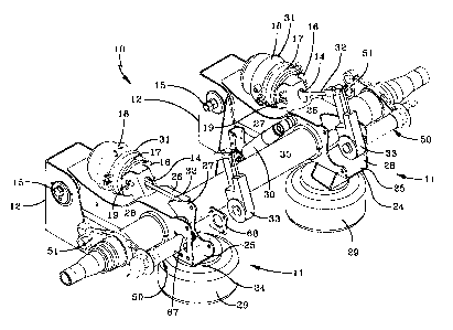
FIG. 2 is an enlarged perspective view of one of the cam shaft
support/enclosure assemblies shown in FIG. 1;
FIG. 3 is a reduced-size exploded view of the assembly shown in
FIG. 2;
FIG. 4 is a fragmentary plan view, with portions broken away and
shown in section and hidden portions shown in phantom lines, of the left-
hand cam shaft support/enclosure assembly shown in FIG. 1, mounted on
an axle and suspension beam of the axle/suspension system;
FIG. 5 is an elevational view of the suspension beam mounting
plate of the cam shaft support/enclosure assembly; and
FIG. 6 is an elevational view, with portions shown in hidden lines,
of the cam tube of the cam shaft support/enclosure assembly of the
present invention.
CA 02379517 2002-O1-15
WO 01/18422 PCT/US00/22666
-6-
Similar numerals refer to similar parts throughout the drawings.
DESCRIPTION OF THE PREFERRED EMBODIMENT
So that one representative environment in which the cam shaft
support/enclosure assembly of the present invention operates, as well as
the invention itself, both can be better understood, an air-ride beam-type
trailing arm axle/suspension system for a tractor-trailer is indicated
generally at 10 and is shown in FIG. 1. Inasmuch as axle/suspension
system 10 includes generally identical suspension assemblies 11, each
suspended from a respective one of a pair of hangers 12, only one of
these suspension assemblies will be described herein. Hanger 12 is, by
any suitable means, securely mounted on and depends from the
underside of the trailer of a semi-trailer or from another heavy duty vehicle
(not shown).
A bushing (not shown) is pivotally mounted on hanger 12 by any
suitable means such as a fastener 15. The bushing preferably is of the
type having multi-functional characteristics. More specifically, the multi-
functional characteristics include required load and deflection ratios, or
static rates, of varying levels in different directions for semi-trailer
axle/suspension system applications. The bushing static rate is stiff in the
horizontal radial direction, so that axle/suspension system 10 remains
substantially perpendicular to the direction of movement of the semi-trailer
despite horizontal loading which may be placed on the axle/suspension
system, and relatively soft in the vertical radial direction, to enable the
suspension system and bushing to absorb vertical loading shocks and
provide a smooth ride for the vehicle occupants and any cargo carried by
the vehicle.
The front end of a trailing arm or beam 24 in turn is rigidly attached
to a mounting tube (not shown) containing the bushing by any suitable
means such as welding. Beam 24 generally is rectangular-shaped and
includes spaced-apart top and bottom walls 25 and 26, respectively, and
CA 02379517 2002-O1-15
WO 01/18422 PCT/US00/22666
_7_
spaced-apart inboard and outboard sidewalls 27 and 28, respectively.
Top wall 25 is formed integrally with sidewalls 27, 28 to form an inverted
generally U-shaped structure. Bottom wall 26 extends between, is welded
to, and interconnects sidewalls 27, 28. An air spring 29 is suitably
mounted on and extends between the upper surface of the rear end of top
wall 25 and the underside of the vehicle. A shock absorber 30 extends
between and is mounted on inboard sidewall 27 of suspension beam 24
and hanger 12.
A dual brake chamber 31 of the vehicle braking system is mounted
on a bracket 16, which in turn is mounted on and depends from bottom
wall 26 of suspension beam 24, by passage of a piston rod 32 of dual
chamber 31 through an opening 14 formed in the bracket. Fasteners 19
formed ~ integrally with a service brake chamber 17, are passed through
openings (not shown) formed in bracket 16 to secure dual brake chamber
31 to the bracket. Dual brake chamber 31 includes service brake
chamber 17 and a parking brake chamber 18. Brake chamber piston 32
in turn is pivotally attached to a slack adjuster 33.
An axle 35 extends between and is immovably captured in
suspension beam 24 and its corresponding opposite suspension beam of
axle/suspension system 10. A set of wheels/tires (not shown) is mounted
on each end of axle 35.
Turning now to the present invention, a cam shaft
support/enclosure assembly 50 is mounted on axle 35 and suspension
beam 24 adjacent to each suspension assembly 11 (Fig. 1 ). Only one of
the cam shaft support/enclosure assemblies 50 will be described
hereinbelow, since the structure and operation of each of the assemblies
is similar. More particularly, cam shaft support/enclosure assembly 50
includes a cam shaft 52 having an S-cam 53 immovably attached to the
outboard end of the cam shaft. A spider 51 is immovably mounted by any
suitable means, typically welds, on axle 35, and a cam tube 54 is
mounted in a bore 55 formed in the cam assembly support end of the
CA 02379517 2002-O1-15
WO 01/18422 PCT/US00/22666
_$_
spider (FIGS. 2-4). More specifically, and as best shown in FIGS. 3, 4
and 6, a reduced diameter outboard end 46 of cam tube 54 forms a
shoulder 56 in the periphery of the cam tube, whereby the cam tube
outboard end is slip-fit in spider bore 55. Shoalder 56 acts as a stop to
prevent outboard movement of seated cam tube 54. A sealant or
adhesive is applied to the exterior of cam tube outboard end 46 and/or the
interior surface of spider bore 55 to limit the ingress of contaminants
and/or moisture into the inboard end of the spider bore, thereby aiding in
preventing damage to the slip fit connection between cam tube 54 and
spider 51, but also aiding in the prevention of entry of contaminants into
the cam tube.
Outboard and inboard bushings 59 and 60, respectively, are
friction-fit in cam tube outboard and inboard ends 46, 47 (FIGS. 3 and 4).
An outboard seal 61 is friction-fit in spider bore 55 and is disposed
adjacent to cam tube outboard end 46. An inboard seal 63 is friction-fit in
cam tube inboard end 47 adjacent to the inboard end of bushing 60. Cam
shaft 52 is rotatably mounted in and passes completely through outboard
and inboard bushings 59, 60 and cam tube 54, so that S-cam 53 is
exposed and is located adjacent to cam tube outboard end 46, and a
splined inboard end 64 of cam shaft 52 is exposed and is located adjacent
to cam tube inboard end 47. A washer 57 is captured about cam shaft 52
between S-cam 53 and spider 51 to prevent friction contact between the
S-cam and the spider.
In accordance with one of the key features of the present invention,
inboard end 47 of generally cylindrical-shaped cam tube 54 is formed with
a flat 66 (Figs. 2-4 and 6). Cam tube inboard end 47 passes freely
through an opening 67 (Fig. 1 ) formed in outboard wall 28 of suspension
beam 24, and through an opening 69 formed in a support plate 68. More
particularly, support plate 68 is attached to the inboard surface of beam
outboard sidewall 28 by any suitable means such as a floating fastener
joint. Plate 68 is formed with correspondingly sized and shaped opening
CA 02379517 2002-O1-15
WO 01/18422 PCT/US00/22666
_g_
69 (FIG. 5) to slip fittingly receive cam tube inboard end 47 formed with
flat 66. This keyhole or generally D-shaped opening 69 formed in
mounting plate 68, and which corresponds to the profile of cam tube
inboard end 47, is important for several reasons, which will be described
in detail immediately below in the description of the operation of cam shaft
support/enclosure assembly 50 of the present invention.
Splined inboard end 64 of cam shaft 52 is meshingly engaged with
the splined interior surface (not shown) of slack adjuster 33, as is well
known in the art and to the literature. Slack adjuster 33 provides for
transfer of in-line loads from brake chamber piston 32 into a torsional load
on cam shaft 52. A snap ring 62 is snappingly engaged in a groove (not
shown) formed in a reduced diameter inboardmost end 71 of cam shaft
52. Tlie location of snap ring 62 inboard relative to slack adjuster 33,
limits inboard axial movement of the slack adjuster and disengagement
from cam shaft 52. Similarly, a washer 58 is captured about cam shaft 52
between cam tube inboard end 47 and slack adjuster 33. A snap ring 70
is snappingly engaged in a groove 75 formed in cam shaft 52 inboard
from and adjacent to cam shaft splined inboard end 64. The combination
of parts of washer 58 and snap ring 70 prevents cam shaft 52 from
moving in an outboard direction any appreciable distance, but also
reduces the play of the cam shaft within cam tube 54, which results in
improved life of seals 61, 63. Finally, the combination of washer 58 and
snap ring 70 also prevents appreciable inboard movement of cam tube
54.
A fitting 72 is mounted in an opening (not shown) formed in cam
tube 54 to enable introduction of a lubricant such as heavy grease into the
interior of the cam tube for lubricating cam shaft 52 and bushings 59, 60.
One of the main advantages of the present invention is that the
improved cam shaft supportlenclosure assembly 50 can improve brake
component life, and in particular the life of seals 61, 63, bushings 59, 60
and cam shaft 52. Specifically, and as discussed hereinabove, there are
CA 02379517 2002-O1-15
WO 01/18422 PCT/US00/22666
-10-
two primary contributors to cam shaft and bushing wear, namely, load-
induced wear and contamination-induced wear. Load-induced wear is
caused by quasi-static and dynamic conditions. In the quasi-static case,
when the vehicle brakes are applied braking forces are reacted in
bushings 59, 60. This case is considered quasi-static due to the relatively
low rotational speed of cam shaft 52 and the steady state condition when
the brakes are held at constant pressure. In this quasi-static state, the
load is greater on outboard bushing 59 than on inboard bushing 60. The
dynamic load case typically develops when the brakes are in the released
condition and cam shaft 52 experiences vibrations due to road inputs.
This results in impact loading of cam shaft 52 against bushings 59, 60.
However, use of cam tube 54 in cam shaft support and enclosure
assemfily 50 of the present invention maintains bushings 59, 60 in coaxial
relationship to effectively prevent excessive quasi-static and dynamic
loads on the bushings. More particularly, this arrangement of parts
prevents excessive rotational friction or binding of cam shaft 52 against
one or more of bushings 59, 60, during brake actuation, and also
improves the load support of the bushings. That is, loads are more evenly
distributed across the surtaces of both bushings 59,60 and there is a
reduced chance of cam shaft 52 contacting a small area or edge of one of
the bushings. The load-bearing area also is increased for cam shaft 52
which also contributes to reduced wear of bushings 59,60. Moreover, use
of cam tube 54 eliminates two seal interfaces and reduces by two the
possible points of ingress of contamination into cam tube 54 as compared
to bushings used without a tube. Cam tube 54 also provides a larger
grease reservoir to assist in trapping and diluting any contaminants that
may migrate past the seals.
In accordance with one of the key features of the present invention,
support plate 68 formed with D-shaped opening 69 provides a means of
reacting rotation of cam tube 54 induced by rotation of cam shaft 52.
More specifically, flat 66 formed in cam tube 54 engages the flat portion F
CA 02379517 2002-O1-15
WO 01/18422 PCT/US00/22666
-11-
(FIG. 5) of support plate opening 69 and is large enough to react torsional
loads imparted by the tube. In direct contrast, many prior art cam
assembly designs weld the cantilevered cam tube to a suspension beam
support plate, and such welds are susceptible to fatigue and failure due to
the many loads reacted by the plate. The present invention eliminates the
possibility of weld fatigue or failure since it is free of welds. Moreover,
the
slip fit, non-welded connection of support plate 68 and cam tube 54 is
easy to assemble in a production environment. In addition, flat 66 is long
enough horizontally to engage support plate 68. More specifically, cam
tube 54 can be positioned in an inboard or an outboard direction a
distance equal to the length of the flat 66, to account for manufacturing
variances in the distance between the two main support points for the
tube, namely spider 51 and suspension beam outboard wall 28. Thus,
custom welding or shimming is not required during assembly of cam
assembly 50 to account for such variances. This arrangement of parts
also enables a single type of cam assembly 50 to be mounted on various
types of axle/suspension systems having differing distances between the
spider and beam, without custom fitting. In contrast, prior art cam shaft
support and enclosure assemblies would have to be custom fit to account
for such manufacturing variances and different axle/suspension systems,
such as by changing the length of tube 54.
The slip fit of cam tube 54 and support plate 68 also
accommodates possible dynamic small scale axial displacements of tube
54 relative to beam 24, which is possible due to the lack of welds. These
displacements are caused by dynamic displacements between spider 51
and beam 24 due to deflections of axle 35. Also, since inboard seal 63
and cam shaft 52 remain static while moving with tube 54, seal life is
improved and therefore the life of bushings 59,60 and cam shaft 52 also
are improved. Also, the arrangement of washer 58 and snap rings 70 and
62 allows replacement of slack adjuster 33 without disturbing the other
components of cam shaft support/enclosure assembly 50.
CA 02379517 2002-O1-15
WO 01/18422 PCT/US00/22666
-12-
It is understood that other shapes of support plate opening 69 and
the corresponding shape of cam tube inboard end 47 engaging that plate
can be utilized without affecting the overall concept of the present
invention. It is also understood that plate 69 could be welded directly to
axle 35 or mounted on a separate bracket that is in turn welded to the
axle. Moreover, it is contemplated that plate 69 could be eliminated
altogether, and keyhole opening 69 could be formed directly in outboard
sidewall 28 of beam 24. It is even contemplated that fitting 72 could serve
the same purpose as flat 66. It is also within the scope of the present
invention to create a friction fit between cam tube 54 and plate 69. In
addition, D-shaped or other keyhole-shaped opening 69 could be formed
i~ spider bore 55, and flat 66 or other keyhole-engaging member could be
formed in or on outboard end 46 of cam tube 54. Finally, it should be
appreciated that cam assembly 50 could be used on all types of heavy
duty vehicles as well as on other types of brake systems, such as a
system where spider 51 extends frontwardly, without affecting the overall
concept of the present invention.
Accordingly, the improved cam shaft support and enclosure
assembly is simplified, provides an effective, safe, inexpensive, and
efficient assembly which achieves all the enumerated objectives, provides
for eliminating difficulties encountered with prior cam shaft support and
enclosure assemblies, and solves problems and obtains new results in
the art.
In the foregoing description, certain terms have been used for
brevity, clearness and understanding; but no unnecessary limitations are
to be implied therefrom beyond the requirements of the prior art, because
such terms are used for descriptive purposes and are intended to be
broadly construed.
Moreover, the description and illustration of the invention is by way
of example, and the scope of the invention is not limited to the exact
details shown or described.
CA 02379517 2002-O1-15
WO 01/18422 PCT/US00/22666
-13-
Having now described the features, discoveries and principles of
the invention, the manner in which the improved cam shaft support and
enclosure assembly is constructed, arranged and used, the
characteristics of the construction and arrangement, and the
advantageous, new and useful results obtained; the new and useful
structures, devices, elements, arrangements, parts and combinations are
set forth in the appended claims.