Sélection de la langue

Search

Sommaire du brevet 2379944 

Énoncé de désistement de responsabilité concernant l'information provenant de tiers

Une partie des informations de ce site Web a été fournie par des sources externes. Le gouvernement du Canada n'assume aucune responsabilité concernant la précision, l'actualité ou la fiabilité des informations fournies par les sources externes. Les utilisateurs qui désirent employer cette information devraient consulter directement la source des informations. Le contenu fourni par les sources externes n'est pas assujetti aux exigences sur les langues officielles, la protection des renseignements personnels et l'accessibilité.

Disponibilité de l'Abrégé et des Revendications

L'apparition de différences dans le texte et l'image des Revendications et de l'Abrégé dépend du moment auquel le document est publié. Les textes des Revendications et de l'Abrégé sont affichés :

  • lorsque la demande peut être examinée par le public;
  • lorsque le brevet est émis (délivrance).
(12) Demande de brevet: (11) CA 2379944
(54) Titre français: SYSTEME DE MOULAGE RADIAL A SIMPLE PASSAGE
(54) Titre anglais: SINGLE PASS RADIUS MOLDING SYSTEM
Statut: Réputée abandonnée et au-delà du délai pour le rétablissement - en attente de la réponse à l’avis de communication rejetée
Données bibliographiques
(51) Classification internationale des brevets (CIB):
  • B26D 1/16 (2006.01)
  • B23Q 5/58 (2006.01)
  • B27C 5/06 (2006.01)
  • B27C 9/04 (2006.01)
  • B27M 3/08 (2006.01)
  • E04B 1/32 (2006.01)
  • E06B 1/00 (2006.01)
(72) Inventeurs :
  • WHITE, ROLLIE NATHANIEL (Etats-Unis d'Amérique)
(73) Titulaires :
  • ROLLIE NATHANIEL WHITE
(71) Demandeurs :
  • ROLLIE NATHANIEL WHITE (Etats-Unis d'Amérique)
(74) Agent: SMART & BIGGAR LP
(74) Co-agent:
(45) Délivré:
(22) Date de dépôt: 2002-04-02
(41) Mise à la disponibilité du public: 2002-10-04
Requête d'examen: 2007-03-30
Licence disponible: S.O.
Cédé au domaine public: S.O.
(25) Langue des documents déposés: Anglais

Traité de coopération en matière de brevets (PCT): Non

(30) Données de priorité de la demande:
Numéro de la demande Pays / territoire Date
09/826,461 (Etats-Unis d'Amérique) 2001-04-04

Abrégés

Abrégé anglais


A molding system to form a decorative use in a single pass and
having a horizontal profile cutter, a first vertical cutter
disposed adjacent an end of the horizontal cutter, a second
vertical cutter secured to a hinged door by means of an extension,
and the extension partially disposed in a recess formed on the
adjacent end of the horizontal cutter.

Revendications

Note : Les revendications sont présentées dans la langue officielle dans laquelle elles ont été soumises.


CLAIMS
1. A molding system comprising a frame, a door hingedly
attached to said frame, an extension extending from said door, a
first cutter rotatably mounted in said extension, a second cutter
mounted on said frame at one end thereof, a recessed cavity formed
on the other end of said second cutter, and said extension at
least partially disposed within said recessed cavity during a
cutting operation.
2. A molding system according to claim 1 wherein a third
cutter is rotatably mounted on said frame adjacent said second
cutter and remote from said recessed cavity.
3. A molding system according to claim 1 wherein a shaving
cutter is horizontally rotatable adjacent said second cutter and
remote from said recessed cavity.
4. A molding system according to claim 1 wherein said first
cutter overlaps said second cutter.
5. A molding system according to claim 1 wherein the free end
of said extension is tapered.
6. A molding system according to claim 2 wherein said first
and third cutters are vertically rotatable.
7. A molding system according to claim 1 wherein said second
cutter is horizontally rotatable.
8. A molding system according to claim 1 wherein said second
cutter is mounted on said frame by means of a bolt and said
extension is disposed immediately adjacent said bolt.
8

9. A molding system according to claim 2 wherein said cutters
include bearings and said bearings are lubricated by means of oil
under pressure.
9

Description

Note : Les descriptions sont présentées dans la langue officielle dans laquelle elles ont été soumises.

CA 02379944 2002-04-02
Docket 11109
SINGLE PASS RADIUS MOLDING SYSTEM
BACKGROUND OF THE INVENTION
[0001] In the production of curved door and window arches, it is
necessary to cut the inner and outer surfaces of the arch as well
as the decorative face or profile of the arch. Historically these
cuts have been made by means of successive separate cutting
operations in order to achieve the completed arch design. Of
course, this means of cutting an,arch is quite time consuming and
labor intensive.
BRIEF SUMMARY OF THE INVENTION
[0002] By this invention, a single pass radius molding system
is provided for a decorative arch. A pair of vertically disposed
cutters are provided to cut the inner and outer surfaces of the
arch and a horizontally disposed cutter is positioned between the
Two vertical cutters to cut the profile of the arch. A recess is
formed in the inner end of the horizontal profile cutter with the
inner vertical cutter rotatably positioned on an extension secured
to a door hinged to the frame. To provide stability, the free end
of the extension is disposed in the recessed end of the horizontal
cutter during a cutting operation.
BRIEF DESCRIPTION OF THE SEVERAL VIEWS OF THE DRAWINGS
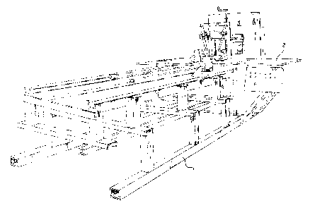
[0003] FIG. 1 is a perspective view of_.the cutting machine
according to this invention;
FIG. 2 is an enlarged perspective view of the rear cutting
1

CA 02379944 2002-04-02
shaft;
FIG. 3 is an enlarged perspective view showing the radius
setting of the machine;
FIG. 4 is an enlarged perspective view of the inner vertical
cutter and the horizontal profile cutter;
FIG. 5 is a top plan view of the cutting operation;
FIG. 6 is an enlarged perspective vievi from below;
FIG. 7 shows a finished arch;
FIG. 8 is an elevational view taken along the line 8-8 in FIG.
7;
FIG: 9 is an enlarged elevational view of the inner cutter
shaft assembly; and
FIG. 10 is an enlarged perspective view of the inner cutter.
DETAILED DESCRIPTION OF THE INVENTION
[000] In the drawings, and with particular reference to FIG. 1,
the numeral 1 designates multiple horizontal and vertical beams
interconnected to form a base for the molding system. Working
surface 2 is supported on frame 1 and backboard 3 is joined to
working surface 2 and extends vertically upward therefrom.
[0005] For the purpose of reducing vibration in the molding
process and as shown in FIG. 2, rollers 4 and 5 are provided and,
in order to accommodate various thicknesses in the workpieces, are
vertically adjustable by means of adjustment assemblies 6 and 7.
Adjustment assemblies 6 and 7 are secured to backboard 3 by any
suitable known means. To complete the basic elements of the
2

CA 02379944 2002-04-02
molding system, motor 8 is provided and is controlled by the manual
manipulation of the associated switches housed within control box
9.
[006] In order to cut a decorative arch shape in workpiece 11,
three molding cutters are utilized. More specifically, molding
cutter 12 is provided for the purpose of cutting the outside
vertical surface of the arch. Molding cutter 12 is adjustable in
the vertical direction by means of threaded adjustment device l3
and horizontally by means of adjustment device 13a both of which
are rotated in either direction, respectfully, by means of cranks
14 and 14a to cause cutter 12 to be raised or lowered and
maneuvered in or out. Operational rotation of molding cutter 12 is
achieved by means of motor 15 which rotates pulley and belt
assembly l6.
[0007] In an alternative configuration, cutter 12 can be
utilized for either the inside or outside cut of the arch
depending on the arch through which workpiece 11 is maneuvered.
For purposes of the outside cut, threads holding the cutter in the
end of the shaft must be left-handed or of a clockwise
configuration. The rotation of the shaft and cutter must be
counterclockwise which allows the cut of the arch to be smooth and
keeps the bit tight in the taper~of the shaft. When utilizing
cutter 12 for the inside cut of the arch, the threads for holding
the cutter in the shaft must be right-handed and the cutting
rotation of the shaft and cutter must be left-handed or clockwise
3

CA 02379944 2002-04-02
also to obtain a smooth cut and keep the bit tight in the taper of
the shaft.
[0008] When cutter 12 is not utilized for the inner cut, the
inner vertical surface of the arch is machined by means of molding
cutter 17 which is rotatably mounted on hinged door 18 as shown in
FIG. 4. The decorative profile cut is achieved by means of
molding cutter 20 which is specially designed with a point zero
shaving blade and cutting edges on both sides and the tip. Molding
cutter 20 is rotatably mounted on shaft 21 and secured thereto by
means of bolt 22 which is affixed through plate 23 to shaft 21. If
cutter 12 is utilized, the cut can be reversed.
[0009] If only a cutting tip is utilized, the back of the arch
is beveled and not cut to a 90 degree angle. Cutter 12a allows the
outside edge to be cut without using cutter 12. Shaving cutter 12a
rotates in a horizontal disposition and allows the cut to begin as
the arch passes through the cutter whereby the back of the arch is
shaved to a 90 degree angle. Both sides have cutting edges so as
to relieve heat buildup in cutter 12a. The cutting edges of cutter
12a should end just below working surface 2 which allows a complete
90 degree dead center cut of the arch. Further, cutter 12a is
removable to allow the arch to be reversed to allow adjustment
between profile cutter 20, cutter 12 and the outside of the arch.
When reversing the arch, if cutter 12a is not removed, it will cut
out the profile of the inside of the reversed arch. Shaft 21 is
not adjustable which allows for complete changing of cutters of
4

CA 02379944 2002-04-02
different profiles thereby reducing setup time. The adjustment is
built into the radius of each profile cutter which, in turn, allows
for later duplication of a particular profile.
[0010] As cutter 17 cuts through the arch, it overlaps the
cutting tip of cutter 20 when cutter 20 begins the profile cut and
cutter 17 acts to finish the profile cut started by cutter 20.
Thi s is necessary because in order to have a tip long enough to
complete the profile cut by cutter 20 when the arch is small,
cutter 20 will cut the inside of the arch and cut into the profile.
Also, cutter 17 has sloped side cutting edges to relieve the
chopping action and maintain a shaving action to relieve the impact
of the cutting forces.
[0011] In the molding operation of a decorative arch, the three
molding cutters are of necessity quite close together and the
constant vibration of the machine can cause a catastrophic failure
when the molding cutters come into contact with each other. In
order to prevent the molding cutters 17 and 20 from coming into
contact, molding cutter 20 is provided with recessed cavity 24 at
one end thereof. Further, molding cutter 17 is secured to hinged
door 18 by means of tapered extension 25 which is integrally
attached to hinged door 18. Therefore, prior to the molding
operation, hinged door 18 is simply closed whereby the free end of
extension 25 enters recessed cavity 24 and comes into near contact
~,aith bolt 22. By this means, any relative movement between molding
cutter 17 and molding cutter 20 is prevented and the molding

CA 02379944 2002-04-02
cutters can be operated at extremely high rpm's without any danger
of touching.
[0012] After hinged door 18 is swung into the operating
position, it is held in place by means of locking rod 28, a portion
of which extends through aperture 29 formed in plate 30 which is
secured to hinged door 18. Finally, locking rod 28 is threaded
into threaded aperture 31. Excess sawdust is removed from the
work area by means of vacuum duct 32. As shown in FIG. 6, cutter
17 is rotated by means of motor 33 through shaft 34.
[ 0013 ] It is known that router cutters must be run at high rpm' s
to achieve smooth cuts. If sealed bearings are utilized, the life
thereof is very short and, if unsealed bearings with dust shields
and an oil mister are utilized, the life is also short due to dust
interfering with the operation of the bearings. By running
bearings in an oil bath, the speed will cause the bearings to clean
themselves thus causing failure.
[0014] According to this invention, oil is forced through the
bearings, which are unsealed, with a high pressure pump circulating
the oil through the bearing and back into a reservoir. This allows
for necessary cooling thereby yielding longer bearing life. By
using a motor and cutting system and a small cutter shaft, both
increased power and high speed rotation of the cutters 12 and 17
are achieved which are not possible with a router motor.
[0015) In operation, workpiece 11 is clamped into position by
means of clamping piston 26 on horizontally movable rail 27.' Then
6

CA 02379944 2002-04-02
workpiece 11 is moved into the desired cutting position whereby
hinged door 18 closed and, if molding cutter 12 is used, lowered
into its cutting position. Following this, workpiece 11 is swung
through the cutters at pivot point 26 resulting in the finished
product as shown in FIGS. 7 and 8.
[0016] An alternative arrangement is depicted in FIGS. 9 and 10
wherein extension 25 is bolted to hinged door 18 through holes 35
and 36 in known manner. Door 18 is provided with lubrication
channels 37, 38 and 39 which cooperate with corresponding channels
disposed in extension 25. In the arrangement of FIGS. 9 and 10,
cutter 17 is disposed above extension 25 by means of shaft 40 which
in turn is rotated by means of drive belt 41. In FIG. 10, collar
42 is pressed onto and strengthens the end of shaft 43 and cutter
17 is mounted in the end of shaft 43.
[0017] Therefore, by this invention, decorative arches are cut
in a high-speed operation with a single pass required in the
cutting operation and any chance of the molding cutters actually
touching each other is prevented.
7

Dessin représentatif
Une figure unique qui représente un dessin illustrant l'invention.
États administratifs

2024-08-01 : Dans le cadre de la transition vers les Brevets de nouvelle génération (BNG), la base de données sur les brevets canadiens (BDBC) contient désormais un Historique d'événement plus détaillé, qui reproduit le Journal des événements de notre nouvelle solution interne.

Veuillez noter que les événements débutant par « Inactive : » se réfèrent à des événements qui ne sont plus utilisés dans notre nouvelle solution interne.

Pour une meilleure compréhension de l'état de la demande ou brevet qui figure sur cette page, la rubrique Mise en garde , et les descriptions de Brevet , Historique d'événement , Taxes périodiques et Historique des paiements devraient être consultées.

Historique d'événement

Description Date
Demande non rétablie avant l'échéance 2010-09-03
Inactive : Morte - Taxe finale impayée 2010-09-03
Réputée abandonnée - omission de répondre à un avis sur les taxes pour le maintien en état 2010-04-06
Réputée abandonnée - les conditions pour l'octroi - jugée non conforme 2009-09-03
Un avis d'acceptation est envoyé 2009-03-03
Lettre envoyée 2009-03-03
Un avis d'acceptation est envoyé 2009-03-03
Inactive : Approuvée aux fins d'acceptation (AFA) 2009-02-23
Modification reçue - modification volontaire 2007-07-16
Lettre envoyée 2007-05-22
Requête d'examen reçue 2007-03-30
Toutes les exigences pour l'examen - jugée conforme 2007-03-30
Exigences pour une requête d'examen - jugée conforme 2007-03-30
Inactive : CIB de MCD 2006-03-12
Demande publiée (accessible au public) 2002-10-04
Inactive : Page couverture publiée 2002-10-03
Inactive : CIB attribuée 2002-07-08
Inactive : CIB en 1re position 2002-07-08
Demande reçue - nationale ordinaire 2002-05-08
Inactive : Certificat de dépôt - Sans RE (Anglais) 2002-05-08
Exigences de dépôt - jugé conforme 2002-05-08

Historique d'abandonnement

Date d'abandonnement Raison Date de rétablissement
2010-04-06
2009-09-03

Taxes périodiques

Le dernier paiement a été reçu le 2009-01-21

Avis : Si le paiement en totalité n'a pas été reçu au plus tard à la date indiquée, une taxe supplémentaire peut être imposée, soit une des taxes suivantes :

  • taxe de rétablissement ;
  • taxe pour paiement en souffrance ; ou
  • taxe additionnelle pour le renversement d'une péremption réputée.

Veuillez vous référer à la page web des taxes sur les brevets de l'OPIC pour voir tous les montants actuels des taxes.

Historique des taxes

Type de taxes Anniversaire Échéance Date payée
Taxe pour le dépôt - générale 2002-04-02
TM (demande, 2e anniv.) - générale 02 2004-04-02 2004-02-13
TM (demande, 3e anniv.) - générale 03 2005-04-04 2005-03-08
TM (demande, 4e anniv.) - générale 04 2006-04-03 2006-02-15
TM (demande, 5e anniv.) - générale 05 2007-04-02 2007-03-26
Requête d'examen - générale 2007-03-30
TM (demande, 6e anniv.) - générale 06 2008-04-02 2008-03-11
TM (demande, 7e anniv.) - générale 07 2009-04-02 2009-01-21
Titulaires au dossier

Les titulaires actuels et antérieures au dossier sont affichés en ordre alphabétique.

Titulaires actuels au dossier
ROLLIE NATHANIEL WHITE
Titulaires antérieures au dossier
S.O.
Les propriétaires antérieurs qui ne figurent pas dans la liste des « Propriétaires au dossier » apparaîtront dans d'autres documents au dossier.
Documents

Pour visionner les fichiers sélectionnés, entrer le code reCAPTCHA :


Pour visualiser une image, cliquer sur un lien dans la colonne description du document. Pour télécharger l'image (les images), cliquer l'une ou plusieurs cases à cocher dans la première colonne et ensuite cliquer sur le bouton "Télécharger sélection en format PDF (archive Zip)" ou le bouton "Télécharger sélection (en un fichier PDF fusionné)".

Liste des documents de brevet publiés et non publiés sur la BDBC .

Si vous avez des difficultés à accéder au contenu, veuillez communiquer avec le Centre de services à la clientèle au 1-866-997-1936, ou envoyer un courriel au Centre de service à la clientèle de l'OPIC.


Description du
Document 
Date
(aaaa-mm-jj) 
Nombre de pages   Taille de l'image (Ko) 
Dessin représentatif 2002-07-09 1 23
Page couverture 2002-09-09 1 46
Description 2002-04-02 7 281
Abrégé 2002-04-02 1 12
Revendications 2002-04-02 2 47
Dessins 2002-04-02 5 146
Certificat de dépôt (anglais) 2002-05-08 1 165
Rappel de taxe de maintien due 2003-12-03 1 109
Rappel - requête d'examen 2006-12-05 1 118
Accusé de réception de la requête d'examen 2007-05-22 1 177
Avis du commissaire - Demande jugée acceptable 2009-03-03 1 162
Courtoisie - Lettre d'abandon (AA) 2009-11-26 1 164
Courtoisie - Lettre d'abandon (taxe de maintien en état) 2010-06-01 1 174
Taxes 2004-02-13 1 32
Taxes 2005-03-08 1 27
Taxes 2006-02-15 1 26
Taxes 2007-03-26 1 29
Taxes 2008-03-11 1 34
Taxes 2009-01-21 1 34