Sélection de la langue

Search

Sommaire du brevet 2380458 

Énoncé de désistement de responsabilité concernant l'information provenant de tiers

Une partie des informations de ce site Web a été fournie par des sources externes. Le gouvernement du Canada n'assume aucune responsabilité concernant la précision, l'actualité ou la fiabilité des informations fournies par les sources externes. Les utilisateurs qui désirent employer cette information devraient consulter directement la source des informations. Le contenu fourni par les sources externes n'est pas assujetti aux exigences sur les langues officielles, la protection des renseignements personnels et l'accessibilité.

Disponibilité de l'Abrégé et des Revendications

L'apparition de différences dans le texte et l'image des Revendications et de l'Abrégé dépend du moment auquel le document est publié. Les textes des Revendications et de l'Abrégé sont affichés :

  • lorsque la demande peut être examinée par le public;
  • lorsque le brevet est émis (délivrance).
(12) Brevet: (11) CA 2380458
(54) Titre français: SEPARE-OEUF EN FIL METALLIQUE
(54) Titre anglais: WIRE EGG SEPARATOR
Statut: Périmé et au-delà du délai pour l’annulation
Données bibliographiques
(51) Classification internationale des brevets (CIB):
  • A47J 43/14 (2006.01)
  • A23J 01/09 (2006.01)
  • A47J 43/22 (2006.01)
(72) Inventeurs :
  • WANG, NIGEL (Taïwan, Province de Chine)
  • KARI, KATHY (Etats-Unis d'Amérique)
(73) Titulaires :
  • COLUMBIA INSURANCE COMPANY
(71) Demandeurs :
  • COLUMBIA INSURANCE COMPANY (Etats-Unis d'Amérique)
(74) Agent: NORTON ROSE FULBRIGHT CANADA LLP/S.E.N.C.R.L., S.R.L.
(74) Co-agent:
(45) Délivré: 2007-01-02
(86) Date de dépôt PCT: 2000-08-29
(87) Mise à la disponibilité du public: 2001-03-08
Requête d'examen: 2003-11-27
Licence disponible: S.O.
Cédé au domaine public: S.O.
(25) Langue des documents déposés: Anglais

Traité de coopération en matière de brevets (PCT): Oui
(86) Numéro de la demande PCT: PCT/US2000/023700
(87) Numéro de publication internationale PCT: US2000023700
(85) Entrée nationale: 2002-01-25

(30) Données de priorité de la demande:
Numéro de la demande Pays / territoire Date
09/387,368 (Etats-Unis d'Amérique) 1999-08-31

Abrégés

Abrégé français

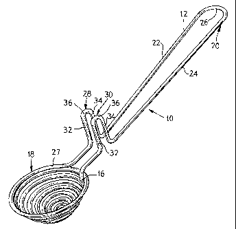
On décrit un sépare-oeuf réalisé à partir d'un brin de fil qui a été plié et torsadé pour former une coupelle dans laquelle le blanc de l'oeuf est séparé du jaune. Le sépare-oeuf comprend également une poignée formée de deux parties sur lesquelles des régions coudées définissent des fentes qui, ensemble, constituent un dispositif de retenue qui permet de fixer le sépare-oeuf sur le bord d'un bol ou d'un saladier. Les régions coudées comprennent des pattes qui peuvent être inclinées suivant un angle par rapport à la poignée, cet angle correspondant globalement à l'angle d'inclinaison du bol pour que la coupelle reste droite et de niveau dans ledit bol.


Abrégé anglais


An egg separator made from a strand of wire which has been bent and twisted to
form a cup in which the white of
the egg is separated from the yolk of the egg. The separator also includes a
handle having two wire arms with bends therein defining
slots which together define a clip which allows the egg separator to be rested
to the rim of a bowl. The bends include arms which
may be inclined at an angle relative to the handle corresponding generally to
the angle at which the wall of the bowl is inclined so
that the cup remains level in the bowl.

Revendications

Note : Les revendications sont présentées dans la langue officielle dans laquelle elles ont été soumises.


-5-
WHAT IS CLAIMED IS:
1. An egg separator comprising a length of wire defining a cup-shaped
portion for receiving the contents of an egg and a handle including arms
having
bends therein defining a clip for resting the egg separator over the rim of a
receptacle.
2. The egg separator of claim 1 wherein the cup-shaped portion is
semi-spherically shaped.
3. The egg separator of claim 1 wherein the bends are generally
inverted U-shaped and define generally U-shaped slots.
4. The egg separator of claim 1 wherein the bends extend above the
respective arms of the handle and include a closed end and two spaced-apart
parallel arms which are angularly oriented relative to the arms of the handle.
5. The egg separator of claim 4 wherein the arms of the bends extend
at approximately a ten (10) degree angle relative to the arms of the handle.
6. The egg separator of claim 5 wherein the arms of the bends extend
in a direction away from the cup-shaped portion.
7. The egg separator of claim 1 wherein the bends in the arms of the
handle are located proximate the cup-shaped portion.
8. An egg separator comprising a single length of wire defining a cup-
shaped portion for receiving the contents of an egg and a handle including two
arms having upwardly extending bends respectively which are angled in a
direction away from said cup and define generally U-shaped slots which
together
define a clip for resting the egg separator over the wall of a receptacle.
9. The egg separator of claim 8 wherein said cup is semi-spherically
shaped.
10. The egg separator of claim 8 wherein each of said bends includes
two spaced-apart parallel arms extending upwardly from said arms of said
handle
and a generally inverted U-shaped closed end therebetween, said arms of said
bends being inclined at an angle relative to said arms of said handle in a
direction
away from said cup.

-6-
11. The egg separator of claim 10 wherein the angle at which said arms
of said bends are inclined corresponds generally to the angle at which the
wall of
the receptacle is inclined.
12. The egg separator of claim 8 wherein said bends in said arms of
said handle are located proximate said cup.

Description

Note : Les descriptions sont présentées dans la langue officielle dans laquelle elles ont été soumises.


WO 01/15546 CA 02380458 2002-O1-25 PCT/US00/23700
-1-
WIRE EGG SEPARATOR
Technical Field of the Invention
The present invention relates to an egg separator adapted to separate the
white of the egg from the yolk of the egg and, more particularly, to an egg
separator made of wire.
Background of the Invention
Various types of implements have been developed and used over the years
to separate the white of an egg from the yolk of the egg. A number of prior
art
patents disclose various structures of these egg separators including U.S.
Patent
No. 1,649,874 which discloses an egg separator which is made from a length of
wire material.
Egg separators of the wire type as disclosed in U.S. Patent No. 1,649,874
have proven satisfactory because they are lightweight and further because the
wire
structure enhances and improves the separation of the white of the egg from
the
yolk of the egg in the cup of the separator.
However, a drawback associated with several of the available egg
separators including the separator disclosed in U.S. Patent No. 1,649,824 is
that
the hook located in front of the egg receiving basket allows only for the
suspension of the egg separator across the opposite walls of a bowl. As a
result,
2 0 the length of the separator is a limiting factor in determining the size
or diameter
of the bowl which can be used.
Thus, there remains a need for an egg separator of the wire type which can
be used with any size bowl regardless of the length of the egg separator.
Summary of the Invention
The present invention relates to an improved egg separator of the wire type
whose use is not limited either by the length of the separator or the size of
the
bowl upon which it is rested.
In accordance with the present invention, the egg separator comprises a
length of wire which has been bent and twisted to define a cup-shaped portion
for
3 0 receiving the contents of an egg and a handle which includes arms with
bends
therein defining a clip which allows the separator to be rested over the lip
or the
rim of a bowl or the like receptacle.

W~ X1/1$$46 CA 02380458 2002-O1-25 PCT/US00/23700
-2-
In one embodiment of the invention, each of the bends defines a generally
inverted U-shaped slot including a closed end and two spaced-apart parallel
arms
which are angularly oriented relative to the arms of the handle.
Further, in this embodiment, the arms of the bends extend in a direction
away from the cup-shaped portion at approximately a 10 degree angle relative
to
the arms of the handle. In accordance with the present invention, the arms of
the
bends are inclined at an angle corresponding generally to the angle at which
the
wall of the bowl is inclined to assure that the cup-shaped portion of the
separator
is seated within the bowl in a generally horizontal and level orientation.
Various other objects, aims, purposes, features, advantages, embodiments,
variations, and the like will be apparent to those skilled in the art form the
teachings of the present specification taken with the associated drawings and
the
appended claims.
Brief Description of the Drawings
In the Drawings,
FIG. 1 is a perspective view of a wire egg separator in accordance with the
present invention;
FIG. 2 is a front elevational view of the wire egg separator of FIG. 1;
FIG. 3 is a perspective view showing the egg separator of FIG. 1 engaged
2 0 to the rim of a bowl; and
FIG. 4 is a side elevational view showing the engagement of the wire egg
separator to the rim of the bowl of FIG. 3.
Description of the Preferred Embodiment
While this invention is susceptible to embodiments in many different
2 5 forms, this specification and the accompanying drawings disclose only a
preferred
form of the invention. This invention is not intended to be limited to the
embodiment so described, however, and the scope of the invention is identified
in
the appended claims.
An egg separator 10 constructed in accordance with the present invention is
3 0 shown in FIGS. l and 2. In the disclosed embodiment, the egg separator 10
is
made from a single elongate length of wire 12 which has opposite ends 14 and
16
and has been appropriately bent and twisted therebetween to form the various

WO 01/15546 CA 02380458 2002-O1-25 PCT/US00/23700
-3-
structural elements of the separator 10. The wire 12 may be made of any
suitable
material such as, for example, stainless steel.
The separator 10 includes a cup-shaped portion 18. The end 14 of the
separator 10 forms the bottom most point of the cup-shaped portion 18 and the
wire 12 is bent and twisted upwardly therefrom into a number of successive
spiral
convolutions of increasing diameter to form a substantially semi-spherically
shaped cup 18.
The separator 10 also includes a handle 20 comprising an element of the
separator 10 where the wire 12 has been bent in the form of two elongate
spaced-
apart and parallel and generally co-planar arms 22 and 24 interconnected by a
distal closed and generally U-shaped end 26. The arm 22 extends unitarily
outwardly from, and generally co-planarly to, the uppermost convolution 27
which
forms the cup-shaped portion 18. The end 16 of the wire 12 forms the end of
the
arm 24 and is connected, as by welding or the like, to the uppermost
convolution
27 forming the cup-shaped portion 18 at a point thereof generally opposite and
symmetrical to the point from which the arm 22 extends outwardly from the
uppermost convolution 27.
The arms 22 and 24 include opposed, generally inverted U-shaped and
upwardly extending respective bends 28 and 30. The bends 28 and 30 are located
2 0 on the handle 20 proximate the cup-shaped portion 18 and each comprises
two
spaced-apart and generally parallel arms 32 and 34 interconnected by a
generally
inverted U-shaped closed end 36.
According to the invention, the arms 32 and 34 are aligned generally
vertically co-planarly with the respective arms 22 and 24 of the handle 20 and
2 5 extend upwardly and angularly therefrom. As shown in FIG. 4, in the
embodiment shown, the arms 32 and 34 extend in a direction away from the cup-
shaped portion 18 at approximately a ten (10) degree angle from the vertical
relative to the arms 22 and 24, respectively.
As shown in FIGS. 3 and 4, the bends 28 and 30 together define a clip
3 0 which allows the separator 10 to be rested over the rim or lip 38 of the
wall 39 of
a bowl or the like receptacle 40 which receives the white of the egg separated
in
the cup-shaped portion 18.

WO 01/15546 CA 02380458 2002-O1-25 PCT/US00/23700
-4-
As shown in FIGS. 3 and 4, the separator 10 is rested over the bowl 40 in
a secure relationship wherein the closed end 36 of the respective bends 28 and
30
is positioned in abutting relationship with the lip 38 of the bowl 40 and the
arms
32 and 34 of the respective bends 28 and 30 are positioned in abutting
relationship
with the inner and outer faces respectively of the wall 39 of the bowl 40.
In accordance with the present invention, the angle at which the arms 32
and 34 are inclined corresponds generally to the angle at which the walls of
most
of the bowls available today are inclined to assure that the cup-shaped
portion 18
is seated within the bowl 40 in a generally level and horizontal orientation.
Unlike the wire egg separator disclosed in U.S. Patent No. 1,649,874
which includes only a hook in front of the egg receiving cup, the use of bends
28
and 30 in the handle of the separator 10 as disclosed in the present invention
allows the separator 10 to be used on any size bowl regardless of the length
of the
separator. The separator 10 of the present invention thus provides the
benefits and
advantages of an egg separator of the wire type while affording the added
benefit
and advantage of being usable with any size bowl.
It will be readily apparent from the foregoing detailed description of the
invention and from the illustrations thereof, that numerous variations and
modifications may be effected without departing from the true spirit and scope
of
2 0 the novel concepts or principles of this invention.

Dessin représentatif
Une figure unique qui représente un dessin illustrant l'invention.
États administratifs

2024-08-01 : Dans le cadre de la transition vers les Brevets de nouvelle génération (BNG), la base de données sur les brevets canadiens (BDBC) contient désormais un Historique d'événement plus détaillé, qui reproduit le Journal des événements de notre nouvelle solution interne.

Veuillez noter que les événements débutant par « Inactive : » se réfèrent à des événements qui ne sont plus utilisés dans notre nouvelle solution interne.

Pour une meilleure compréhension de l'état de la demande ou brevet qui figure sur cette page, la rubrique Mise en garde , et les descriptions de Brevet , Historique d'événement , Taxes périodiques et Historique des paiements devraient être consultées.

Historique d'événement

Description Date
Le délai pour l'annulation est expiré 2018-08-29
Lettre envoyée 2017-08-29
Accordé par délivrance 2007-01-02
Inactive : Page couverture publiée 2007-01-01
Inactive : Taxe finale reçue 2006-10-10
Préoctroi 2006-10-10
Un avis d'acceptation est envoyé 2006-09-01
Lettre envoyée 2006-09-01
Un avis d'acceptation est envoyé 2006-09-01
Inactive : Approuvée aux fins d'acceptation (AFA) 2006-06-01
Modification reçue - modification volontaire 2004-04-15
Lettre envoyée 2003-12-17
Toutes les exigences pour l'examen - jugée conforme 2003-11-27
Exigences pour une requête d'examen - jugée conforme 2003-11-27
Requête d'examen reçue 2003-11-27
Exigences relatives à la révocation de la nomination d'un agent - jugée conforme 2003-09-16
Inactive : Lettre officielle 2003-09-16
Lettre envoyée 2003-09-16
Exigences relatives à la nomination d'un agent - jugée conforme 2003-09-16
Demande visant la révocation de la nomination d'un agent 2003-08-28
Demande visant la nomination d'un agent 2003-08-28
Lettre envoyée 2003-08-26
Inactive : Demande ad hoc documentée 2003-04-15
Inactive : Lettre officielle 2003-04-15
Demande visant la révocation de la nomination d'un agent 2003-03-27
Demande visant la nomination d'un agent 2003-03-27
Lettre envoyée 2003-03-13
Inactive : Lettre officielle 2003-03-13
Inactive : Lettre officielle 2003-02-19
Inactive : Lettre officielle 2003-02-17
Inactive : Transfert individuel 2003-01-14
Exigences relatives à la révocation de la nomination d'un agent - jugée conforme 2003-01-06
Inactive : Lettre officielle 2003-01-06
Exigences relatives à la nomination d'un agent - jugée conforme 2003-01-06
Demande visant la révocation de la nomination d'un agent 2002-12-10
Demande visant la nomination d'un agent 2002-12-10
Inactive : Lettre de courtoisie - Preuve 2002-07-23
Inactive : Page couverture publiée 2002-07-23
Inactive : Notice - Entrée phase nat. - Pas de RE 2002-07-19
Inactive : CIB attribuée 2002-06-06
Inactive : CIB en 1re position 2002-06-06
Demande reçue - PCT 2002-05-11
Exigences pour l'entrée dans la phase nationale - jugée conforme 2002-01-25
Demande publiée (accessible au public) 2001-03-08

Historique d'abandonnement

Il n'y a pas d'historique d'abandonnement

Taxes périodiques

Le dernier paiement a été reçu le 2006-08-04

Avis : Si le paiement en totalité n'a pas été reçu au plus tard à la date indiquée, une taxe supplémentaire peut être imposée, soit une des taxes suivantes :

  • taxe de rétablissement ;
  • taxe pour paiement en souffrance ; ou
  • taxe additionnelle pour le renversement d'une péremption réputée.

Les taxes sur les brevets sont ajustées au 1er janvier de chaque année. Les montants ci-dessus sont les montants actuels s'ils sont reçus au plus tard le 31 décembre de l'année en cours.
Veuillez vous référer à la page web des taxes sur les brevets de l'OPIC pour voir tous les montants actuels des taxes.

Titulaires au dossier

Les titulaires actuels et antérieures au dossier sont affichés en ordre alphabétique.

Titulaires actuels au dossier
COLUMBIA INSURANCE COMPANY
Titulaires antérieures au dossier
KATHY KARI
NIGEL WANG
Les propriétaires antérieurs qui ne figurent pas dans la liste des « Propriétaires au dossier » apparaîtront dans d'autres documents au dossier.
Documents

Pour visionner les fichiers sélectionnés, entrer le code reCAPTCHA :


Pour visualiser une image, cliquer sur un lien dans la colonne description du document. Pour télécharger l'image (les images), cliquer l'une ou plusieurs cases à cocher dans la première colonne et ensuite cliquer sur le bouton "Télécharger sélection en format PDF (archive Zip)" ou le bouton "Télécharger sélection (en un fichier PDF fusionné)".

Liste des documents de brevet publiés et non publiés sur la BDBC .

Si vous avez des difficultés à accéder au contenu, veuillez communiquer avec le Centre de services à la clientèle au 1-866-997-1936, ou envoyer un courriel au Centre de service à la clientèle de l'OPIC.


Description du
Document 
Date
(aaaa-mm-jj) 
Nombre de pages   Taille de l'image (Ko) 
Dessin représentatif 2002-07-18 1 10
Abrégé 2002-01-24 1 58
Revendications 2002-01-24 2 52
Dessins 2002-01-24 2 46
Description 2002-01-24 4 181
Dessin représentatif 2006-11-30 1 12
Rappel de taxe de maintien due 2002-07-21 1 114
Avis d'entree dans la phase nationale 2002-07-18 1 208
Demande de preuve ou de transfert manquant 2003-01-27 1 102
Courtoisie - Certificat d'enregistrement (document(s) connexe(s)) 2003-03-12 1 130
Accusé de réception de la requête d'examen 2003-12-16 1 188
Avis du commissaire - Demande jugée acceptable 2006-08-31 1 162
Avis concernant la taxe de maintien 2017-10-09 1 181
PCT 2002-01-24 1 33
Correspondance 2002-07-18 1 24
Correspondance 2002-12-09 3 77
Correspondance 2003-01-05 1 13
Correspondance 2003-01-05 1 16
Correspondance 2003-02-16 1 18
Correspondance 2003-02-18 1 18
PCT 2002-01-25 3 141
Correspondance 2003-03-12 1 18
Correspondance 2003-03-26 3 91
Correspondance 2003-04-14 1 16
Correspondance 2003-08-27 3 76
Correspondance 2003-09-15 1 14
Correspondance 2003-09-15 1 18
Correspondance 2003-09-15 1 16
Correspondance 2003-09-15 1 6
Taxes 2003-08-25 1 22
Correspondance 2006-10-09 1 38