Note : Les descriptions sont présentées dans la langue officielle dans laquelle elles ont été soumises.
CA 02381092 2002-O1-23
WO 01/51389 PCT/USO1/00534
DOWEL DRIVE FOR INCREASED TORQUE TRANSFER
CROSS-REFERENCE TO RELATED APPLICATION
This application claims the benefit of U.S. Provisional Application No.
60/175,162, filed January 7, 2000.
BACKGROUND OF THE INVENTION
The present invention relates generally to torque transfer assemblies and,
more particularly, to a torque transfer assembly assembled with reinforced
fasteners so that it can better withstand shear force.
Torque transfer assemblies, i.e. sprocket assemblies, are used to transmit
torque in a wide variety of applications, from bicycles to clocks to
industrial
sized augers. Some of these applications require very little torque to perform
a
given function, i.e. a wristwatch. Other applications may experience high
torque, i.e. auger systems that are used to literally move tons of materials
such
as concrete, rock, or agricultural products.
Many torque transfer assemblies are composed of disks, i.e. sprockets,
spaced apart along a rotational axis. The disks are often held together with
bolts
that have their longitudinal axes aligned with the rotational axis. Thus, when
one sprocket or disk is subjected to a load that is resisted by the connected
sprockets or disks, the bolts experience shear forces. Such resistance can
occur
when a driving disk is trying to turn a shaft that is connected to a loaded
disk,
i.e. when a motor is driving an auger by means of a sprocket assembly.
As an example, a typical prior-art sprocket assembly 10 is shown in Fig.
1. The weakest point of such an assembly is on the bolt threads 24 where the
stub shaft 12 and sprocket 14 meet. The bolts 20 can experience shear failure
at
this point. The problem could be alleviated by using larger diameter bolts or
bolts made of a higher strength material, or by increasing the bolt circle.
However, these are undesirable solution because such bolts are significantly
more expensive, and increasing the bolt circle would require a shaft that is
bulkier, heavier, and more expensive. Thus, there remains a need for a
fastener
CA 02381092 2002-O1-23
WO 01/51389 PCT/LTSO1/00534
that will not readily experience shear failure due to high torque loads, and
not
significantly increase the cost or bulkiness of the torque transfer assembly.
2
CA 02381092 2002-O1-23
WO 01/51389 PCT/USOI/00534
SUMMARY OF THE INVENTION
Therefore, in view of the problems associated with the above torque
transfer assemblies, it is an object of the present invention to provide a
reinforced torque transfer assembly that 1 ) can withstand relatively high
shear
stresses, 2) can be used with existing torque transfer assemblies with only
minimal modification, and 3) does not significantly increase the cost of the
torque transfer assembly.
These and other objectives are met by the reinforced torque transfer
assembly of the present invention. For the purpose of demonstration, the
torque
transfer assembly is shown in use in a sprocket assembly, in particular a
sprocket assembly used to transmit torque to an auger system used in an
agricultural application. This example is not intended to limit the scope of
the
invention.
In one aspect of the present invention, a torque transfer assembly is
composed of at least one disk member and a shaft. The disk member is attached
to the shaft with at least one fastener that is reinforced with a tube key.
The
disk member may be a sprocket or the like wherein the sprocket is mounted
onto the shaft with the reinforced fastener so that the tube key is positioned
on a
portion of the fastener that experiences shear stress. In another aspect of
the
present invention, a method of driving an auger with the reinforced torque
transfer assembly is claimed. In the method, a torque transfer assembly is
presented. The torque transfer assembly is composed of at least a first disk
member and a second disk member attached to a shaft with reinforced fasteners.
The auger is attached to the torque transfer assembly. Finally, the first disk
member is rotated in order to drive the auger.
In another aspect of the present invention, a mixing tank, i.e. for mixing
hay and the like, composed one or more augers each connected to a torque
transfer assembly. The torque transfer assembly is composed of a at least one
disk mounted onto a shaft with tube-key reinforced fasteners.
3
CA 02381092 2002-O1-23
WO 01/51389 PCT/USO1/00534
The present invention will be better understood from the following
detailed description of the invention, read in connection with the drawings as
hereinafter described.
BRIEF DESCRIPTION OF THE DRAWINGS
FIG. 1 is a front end view of a prior-art bolted torque transfer assembly;
FIG. 2 is a cross-sectional view of the bolted torque transfer assembly of
FIG. 1 taken along lines 2-2, showing the engagement of bolts through stacked
sprockets and into a stub shaft;
FIG. 3 is a front end view of an embodiment of a reinforced torque
transfer assembly according to the invention, showing stacked sprockets
mounted on the stub shaft;
FIG. 4 is a cross-sectional view of the reinforced torque transfer
assembly of FIG. 3 taken along lines 4-4, showing the engagement of a tube key
and bolts through the stacked sprockets and into the stub shaft;
FIG. 5 is a cross-sectional view of another embodiment of a reinforced
torque transfer assembly, showing stacked sprockets;
FIG. 6 is a cross-sectional view of another embodiment of a reinforced
torque transfer assembly, showing a single sprocket mounted on the stub shaft;
FIG. 7 is a perspective view of the reinforced torque transfer assemblies
of FIGS. 3-6, mounted in an auger-type feed mixer; and
FIG. 8 is a perspective view of the assembly of FIG. 1 attached to an
auger drive shaft.
FIG 9. is a perspective view of a prior-art mixer assembly.
DESCRIPTION OF THE PREFERRED EMBODIMENT
The invention provides an apparatus and method of power transfer that
increases the torsional load carrying capacity of a torque transfer assembly,
wherein the assembly is composed of disk members held together with fasteners
such as threaded bolts.
FIGS. 1 and 2 illustrate a sample prior-art torque transfer assembly 10.
As shown by example of a sprocket assembly, assembly 10 includes a shaft
4
CA 02381092 2002-O1-23
WO 01/51389 PCT/USO1/00534
such as stub shaft 12, a large diameter sprocket 14, a sprocket spacer 16, and
a
small diameter sprocket 18. The sprockets 14, 18 are stacked together with
spacer 16 therebetween, and mounted onto stub shaft 12 with threaded bolts 20.
Specifically, threaded bolts 20 extend into a bore 21 through sprockets 14, 18
and spacer 16, and a bore 22 in stub shaft 12. Bores 21, 22 are substantially
parallel to the rotational axis of the shaft such as stub shaft 12. The
function of
bolts 20 is to keep sprocket spacer 16 and the rest of the sprocket assembly
connected to stub shaft 12. However, in the prior art assembly 10, the bolt
threads cause stress concentrations on the bolt shaft. Therefore, the threaded
portion 24 on bolts 20 is the weakest part of the bolt. Problematically, this
part
of bolt 20 supports the highest amount of shear stress with the assembly being
linked to and supported at joint 25 between sprocket 14 and stub shaft 12 by
threaded part 24 of bolts 20. Consequently, bolts 20 linking sprockets 14, 18
to
stub shaft 12 can fail due to shear stress. This can also be true for non-
threaded
fasteners.
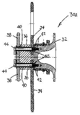
FIGS. 3 and 4 depict an embodiment of a reinforced torque transfer
assembly 30a, according to the invention. The assembly 30a includes a shaft
such as a stub shaft 32, a large diameter sprocket 34, a sprocket spacer 36,
and a
small diameter sprocket 38. The sprockets 34, 38 are stacked with spacer 36
therebetween, and large sprocket 38 mounted on stub shaft 32.
Advantageously, assembly 30a provides a plurality of thick walled
dowels or tube keys 40 that mate into a bore 42 in stub shaft 32. Preferably,
the
tube key thickness about 7 millimeters (mm). Further, the tube keys 40 are
preferably made from carbon steel tubing. Bolts 44 are then mounted through
sprockets 34, 38 and into tube keys 40 in stub shaft 32. Therefore, the joint
45
between sprocket 34 and the stub shaft 32 is strengthened by the tube keys 40.
The new assembly 30a transfers load to the combined tube key 40 and bolt 44
assembly.
FIG. 5 depicts another embodiment of a reinforced torque transfer
assembly according to the invention, designated as 30b. The drive assembly
30b includes a stub shaft 32, a large diameter sprocket 34 and a small
diameter
5
CA 02381092 2002-O1-23
WO 01/51389 PCT/USO1/00534
sprocket 38, with a spacer 36 therebetween. The tube key is designated as 40.
The drive assembly 30b is similar to the stacked assembly 30a except that the
position of the sprockets are reversed, with small sprocket 38 being mounted
on
the stub shaft 32.
FIG. 6 depicts another embodiment of a reinforced torque transfer
assembly, designated as 30c. The drive assembly 30c is composed of a single
sprocket 46 mounted on a stub shaft 32. The tube key is designated as 40.
FIG. 7 illustrates the arrangement of the various reinforced torque
transfer assemblies in a feed mixer composed of stacked augers within a mixing
tank. The reinforced torque transfer system can also be advantageously used in
a feed mixer such as those disclosed in U.S. Patent Nos. 4,597,672, 4,506,990
and 4,741,625 (Neier), incorporated herein by reference, and other torque-
driven mechanisms.
As shown, feed mixer 50 is composed of stacked augers including two
top augers 54, 56 positioned above two bottom augers (not shown). Each of the
augers include central shafts that are rotatably supported and extend through
the
rearward end wall 57 of the mixer. The two bottom augers rotate clockwise to
move hay or other feed material to the front 52 of mixer 50 where the material
moves upward to the two top augers 54, 56. Top augers 54, 56 rotate to the
inside in the direction of arrow 58, to move material to the back end 60 of
mixer
50 where the material cascades to the two bottom augers, whereupon the mixing
and blending process is repeated. Upon engagement of the drive linkage, which
includes reinforced torque transfer assemblies 30 a-d, the upper and lower
augers are rotated to cause movement of feed in a circulating path.
The reinforced torque transfer assemblies 30a-d are shown mounted in
the rear end 60 of an auger-type mixer 50. At the front end 52 of mixer 50, a
power take-off shaft 51 (as shown in a similar prior art mixer in Fig. 9)
connects
to a tractor. A line shaft 53 extends underneath mixer 50 from front end 52 to
rear end 60, and is connected to a drive mechanism. On the lower right side of
mixer 50, assembly 30a (depicted in FIGS. 3-4) is connected to a bottom auger
6
CA 02381092 2002-O1-23
WO 01/51389 PCT/USO1/00534
61 (FIG. 8), and preferably includes a large diameter sprocket 34 positioned
behind a small diameter sprocket 38, with spacer 36 therebetween.
On the lower left side of the mixer, assembly 30b (depicted in FIG. 5) is
connected to the left hand bottom auger, and preferably includes a large
diameter sprocket 34 positioned in front of the small diameter sprocket 38
(shown in phantom), with spacer 36 therebetween.
On the upper right side of the mixer, a torque transfer assembly 30d is
connected to the top auger 56. Assembly 30d is similar to that shown in Fig.
5,
except that it is preferably composed of a single medium-sized sprocket
(rather
than the large-sized sprocket of assembly 30b), and sprocket 38 is replaced by
a
dummy plate.
On the upper left side of the mixer, drive mechanism 30c, connected to
the top auger 54, is a stacked arrangement as shown in Fig. 6. Sprocket 46 is
connected by chain 78 to a preferably small sprocket 38 (shown in phantom)
positioned below on the lower left side of the mixer.
The combined assembly preferably employs two stages of reduction to
power the bottom auger drives, and three stages of reduction to power the top
auger drives, by means of the change in size of the sprocket and chain
connection between sprockets. Different stages of power reduction may be
achieved by replacing the torque transfer assembly sprockets with sprockets of
different sizes.
Line shaft 51 extends underneath the mixer and powers a small drive
sprocket (not shown) located in the center lower portion of the rear of the
mixer.
The small drive sprocket is connected by a chain to a large diameter sprocket
66
in the upper middle section. Referring again to Fig. 7, a center jack-shaft is
mounted on the large upper sprocket 66, and supports a small diameter drive
sprocket (located behind sprocket 66). The small drive sprocket is connected
by
a chain 72 to the large diameter sprocket 34 mounted on the left-bottom auger
positioned beneath the top auger 54. Small drive sprocket is also connected by
a chain 74 to the large diameter sprocket 34 mounted on the right-bottom auger
positioned beneath right-top auger 56. On the right-bottom side, small
diameter
7
CA 02381092 2002-O1-23
WO 01/51389 PCT/USO1/00534
drive sprocket 38 is stacked in front of the large sprocket 34, and is
connected
by a chain 76 to sprocket 34 mounted on top-right auger 56. On the left-bottom
side, small diameter drive sprocket 38 (shown in phantom) is stacked behind
the
large sprocket 34, and is connected by a chain 78 to sprocket 46 mounted on
top
auger 54.
The drive or the torque transfer assemblies 30a-d are bolted to the lower
and upper auger drive shafts and auger tube assemblies, preferably with
multiple, evenly spaced bolts. Such an attachment is shown in FIG. 8, with
regard to assembly 30a attached to the bottom auger 61. Upon engagement of
the drive linkage, the upper and lower augers are rotated to cause movement of
feed in a circulating path. In particular, the bottom sprockets 34 on either
side
of the mixer drive the bottom augers, and torque is transferred to sprockets
38 in
the stack, which, in turn, drive the upper sprockets 46 and 34, that
respectively
drive the top augers 56, 54.
The reinforced drive of the present invention improves reliability in
tough hay processing and mixing situations. Tube keys 40, which are
"doweled" through the sprocket and into the stub shaft 32, significantly
increase
the shear stress capacity, increasing the shear strength by about three times
compared to previously known designs. The use of the tube keys 40 also
eliminates placing the greatest shear stress on the weakest part of the bolt,
i.e.,
the threaded section. Thus, as the chain pulls on and rotates the sprocket,
the
bolts resist tension and maintain the sprockets mounted on the stub shaft.
The invention has been described by references to detailed examples and
methodologies. These examples are not meant to limit the scope of the
invention. Variations within the concepts of the invention are apparent to
those
skilled in the art.
8