Sélection de la langue

Search

Sommaire du brevet 2381480 

Énoncé de désistement de responsabilité concernant l'information provenant de tiers

Une partie des informations de ce site Web a été fournie par des sources externes. Le gouvernement du Canada n'assume aucune responsabilité concernant la précision, l'actualité ou la fiabilité des informations fournies par les sources externes. Les utilisateurs qui désirent employer cette information devraient consulter directement la source des informations. Le contenu fourni par les sources externes n'est pas assujetti aux exigences sur les langues officielles, la protection des renseignements personnels et l'accessibilité.

Disponibilité de l'Abrégé et des Revendications

L'apparition de différences dans le texte et l'image des Revendications et de l'Abrégé dépend du moment auquel le document est publié. Les textes des Revendications et de l'Abrégé sont affichés :

  • lorsque la demande peut être examinée par le public;
  • lorsque le brevet est émis (délivrance).
(12) Brevet: (11) CA 2381480
(54) Titre français: EQUIPEMENT POUR LE LESSIVAGE DE LA MATIERE SOLIDE CONTENUE DANS UNE BOUE
(54) Titre anglais: EQUIPMENT FOR THE LEACHING OF SOLID MATTER FROM SLUDGE
Statut: Durée expirée - au-delà du délai suivant l'octroi
Données bibliographiques
(51) Classification internationale des brevets (CIB):
  • C02F 11/06 (2006.01)
(72) Inventeurs :
  • TAKALA, HEIKKI (Finlande)
  • OINONEN, YRJO (Finlande)
  • HOGLUND, KURT (Finlande)
(73) Titulaires :
  • OUTOTEC OYJ
(71) Demandeurs :
  • OUTOTEC OYJ (Finlande)
(74) Agent: NORTON ROSE FULBRIGHT CANADA LLP/S.E.N.C.R.L., S.R.L.
(74) Co-agent:
(45) Délivré: 2007-03-13
(86) Date de dépôt PCT: 2000-08-10
(87) Mise à la disponibilité du public: 2001-02-22
Requête d'examen: 2003-12-03
Licence disponible: S.O.
Cédé au domaine public: S.O.
(25) Langue des documents déposés: Anglais

Traité de coopération en matière de brevets (PCT): Oui
(86) Numéro de la demande PCT: PCT/FI2000/000682
(87) Numéro de publication internationale PCT: FI2000000682
(85) Entrée nationale: 2002-02-11

(30) Données de priorité de la demande:
Numéro de la demande Pays / territoire Date
19991719 (Finlande) 1999-08-12

Abrégés

Abrégé français

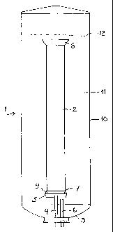
Cette invention se rapporte à un équipement permettant le lessivage de la matière solide contenue dans une boue à l'aide d'un gaz contenant de l'oxygène, cet équipement comprenant un réacteur allongé (1) comportant un tuyau central (2) et, partant du fond du réacteur (3), un mélangeur à double action (5) dirigé vers le haut. Ce mélangeur est situé à proximité du bord inférieur du tuyau central. Les aubes supérieures (13) du mélangeur produisent un courant d'aspiration vers le bas à partir du tuyau central, et les aubes inférieures (14) dispersent le gaz devant être injecté dans la boue sous la forme de petites bulles, ce qui empêche la matière solide de se déposer au fond du réacteur.


Abrégé anglais


The present invention concerns equipment for the leaching of
solid matter from a sludge with the aid of a gas containing oxygen, the said
equipment comprising a tall reactor (1) equipped with a central pipe (2) and
from the
reactor bottom (3), an upward-directed double-action mixer (5). The mixer is
situated in the vicinity of the lower edge of the central pipe: the upper
blades (13) of
the mixer produce a downward suction flow from the central pipe, and the lower
blades (14) disperse the gas to be fed into the sludge in the form of small
bubbles,
thereby preventing the solid matter from settling to the bottom of the
reactor.

Revendications

Note : Les revendications sont présentées dans la langue officielle dans laquelle elles ont été soumises.


-6-
What is claimed is:
1. Equipment for leaching of a sludge containing solid matter aided by a gas
containing
oxygen, the equipment comprising a tubular reactor, with a height greater than
its diameter and
which is equipped with a concentric central pipe and a double-action mixer
having upper blades
and lower blades, the mixer supported by a shaft that extends upwards from the
bottom of the
reactor, the central pipe of the reactor extending to the bottom part of the
reactor, the shaft
having an inlet that is at the bottom part of the reactor, the mixer being
located in the immediate
vicinity of the lower edge of the central pipe, the upper part of the mixer
being situated inside the
central pipe, the upper blades of the mixer producing a downward suction flow
from the central
pipe and the lower blades of the mixer dispersing the gas into the sludge in
the form of small
bubbles to prevent solid matter in the sludge from settling to the bottom of
the reactor, the flow
cross-section area remaining between the mixer and the central pipe adjusted
to be less than half
of the flow cross-section area in the central pipe, and a feeding member for
gas containing
oxygen extending underneath the bottom of the mixer.
2. The equipment according to claim 1, wherein the double-action mixer
comprises a
horizontal plate, the lower blades are fixed under the horizontal plate and
the upper blades are
fixed above the horizontal plate.
3. The equipment according to claim 2, wherein the lower blades are
essentially vertical to
the horizontal plate.
4. The equipment according to anyone of claims 1 to 3, wherein the upper
blades are curved
upper blades.
5. The equipment according to anyone of claims 1 to 4, wherein the lower
blades are
essentially rectangular in form.
6. The equipment according to anyone of claims 1 to 5, wherein the lower part
of the upper
blades are essentially rectangular in form with a smoothly tapered upper part.
7. The equipment according to anyone of claims 1 to 6, wherein the lower edge
of the
central pipe is at a height from the reactor bottom which is between 0.3-0.5
times that of the
diameter of the reactor.

-7-
8. The equipment according to anyone of claims 1 to 7, wherein the flow cross-
section area
remaining between the mixer and the central pipe is adjusted to be at most one
third of the flow
cross-section area in the central pipe.
9. The equipment according to anyone of claims 1 to 8, wherein the lower part
of the central
pipe is equipped with a conical extension.
10. The equipment according to anyone of claims 1 to 9, wherein the upper part
of the central
pipe is equipped with a conical extension.
11. The equipment according to anyone of claims 1 to 10, wherein the lower
edge of the
central pipe is at a height from the reactor bottom, which is 0.2-1.0 times
that of the diameter of
the reactor.
12. The equipment according to anyone of claims 1 to 11, wherein the cross-
section ratio of
the central pipe and its surrounding reactor casing is under 0.1.

Description

Note : Les descriptions sont présentées dans la langue officielle dans laquelle elles ont été soumises.


CA 02381480 2002-02-11
WO 01/12308 PCT/FI00/00682
1
EQUIPMENT FOR THE LEACHING OF SOLID MATTER FROM SLUDGE
The present invention concerns equipment for the leaching of solid matter
from a sludge with the aid of a gas containing oxygen, the said equipment
comprising a tall reactor equipped with a central pipe and an
upward-directed double-action mixer at the bottom of the reactor. The mixer
is situated in the vicinity of the lower edge of the central pipe: the upper
blades of the mixer produce a downward suction flow from the central pipe
and the lower blades disperse the gas to be fed into the sludge in the form
l0 of small bubbles, thereby preventing the solid matter from settling to the
bottom of the reactor.
In leaching of a sludge containing solid matter, such as for example metal
concentrate, it is important that the participatory oxygen in the leaching,
being introduced in the form of oxygen or gas containing oxygen, must firstly
dissolve into the solid-containing sludge, in order that the oxygen can
participate in the leaching reactions of the solid matter. A tall reactor is
used
for the improvement of the dissolution of the oxygen, whereupon, as
compared to normal atmospheric reactors, great hydrostatic pressure forms
at the bottom of the reactor (1.5 - 3.0 atm, i.e. 0.15 - 0.30 MPa), due to
which the oxygen dissolves well in the reaction solution and thereby
catalyses the dissolution of the solid matter.
In the prior art it is known for example US Pat. No. 4,648,973, wherein the
equipment concerns a reactor with a height many times greater than its
diameter, inside which is located a concentric pipe. The sludge is fed into
the upper part of the central pipe, as is the oxygen. For recirculation of the
sludge, the central pipe is equipped with a mixer suspended from the top
downwards, which pumps the sludge down the central pipe and the sludge
then passes up through the space between the reactor and the internal pipe.

CA 02381480 2006-11-09
2
The ratio between the diameters of the central pipe and outer pipe is between
0.4 and
0.85.
Now, the present invention being developed concerns an equipment that
comprises a
tall reactor for the leaching of solid matter from a sludge, such as metal
concentrate.
The height of the reactor is many times greater than its diameter and the
reactor is
equipped with a central pipe extending to the bottom part, a mixer being
located in the
vicinity of the lower part of the central pipe and a feeding member for gas
containing
oxygen. The shaft of the mixer extends upwards from the bottom of the reactor.
The
mixer itself consists of an essentially horizontal central plate, with curved
blades fixed
above it and essentially straight blades fixed underneath the plate. The
blades located
above the central plate produce a downward sucking flow of sludge from the
central
pipe and, with the aid of the blades below the plate, the gas containing
oxygen to be
fed into the lower part of the reactor is dispersed into the sludge in the
form of small
bubbles, thereby preventing the sludge from precipitating to the bottom of the
reactor.
The essential features of the present invention are laid out in the enclosed
claims.
A particularly preferred aspect of the invention relates to an equipment for
leaching of
a sludge containing solid matter aided by a gas containing oxygen, the
equipment
comprising a tubular reactor, with a height greater than its diameter and
which is
equipped with a concentric central pipe and a double-action mixer having upper
blades and lower blades, the mixer supported by a shaft that extends upwards
from the
bottom of the reactor, the central pipe of the reactor extending to the bottom
part of
the reactor, the shaft having an inlet that is at the bottom part of the
reactor, the mixer
being located in the immediate vicinity of the lower edge of the central pipe,
the upper
part of the mixer being situated inside the central pipe, the upper blades of
the mixer
producing a downward suction flow from the central pipe and the lower blades
of the
mixer dispersing the gas into the sludge in the form of small bubbles to
prevent solid
matter in the sludge from settling to the bottom of the reactor, the flow
cross-section
area remaining between the mixer and the central pipe adjusted to be less than
half of
the flow cross-section area in the central pipe, and a feeding member for gas
containing oxygen extending underneath the bottom of the mixer.

CA 02381480 2006-11-09
2a
As mentioned above, it is essential to the equipment that the mixer is located
in the
immediate vicinity of the lower edge of the central pipe, whereby the cross-
section
area of the discharge orifice remaining between the central pipe and the mixer
is less
than half the cross-section area of the central pipe, preferably at most one
third of the
cross-section area of the pipe. Thus the flow rate, from the central pipe, of
the
downward-flowing sludge increases at least twofold in comparison to the flow
rate
taking place in the central pipe. The nearer the mixer is located to the lower
end of the
pipe, the better the suction building up to the central pipe. In practice the
limit is set
by the tolerances, which result from the bending of the shaft and from the
flexibility
and dimensioning of the other parts. At the aforementioned cross-sectional
area ratio,
such a flow rate is achieved that

CA 02381480 2002-02-11
WO 01/12308 PCT/FI00/00682
3
the downward-directed solution flow is faster than the climbing rate of the
gas bubbles, and the upward flow rate of the solution in the casing of the
reactor is greater than the settling rate of the particles of solid matter.
The mixer used in the method according to the invention is of double-action,
it is formed of two parts having an essentially horizontal plate between them.
Curved blades are fixed above the horizontal plate which suck sludge
downward in the central pipe. The blades fixed underneath the horizontal
plate form a straight-bladed turbine mixer. As the gas containing oxygen is
l0 fed underneath the mixer installed in the bottom part of the reactor, the
lower
part of the mixer disperses the feed gas into very small bubbles, this
assisting the dissolution of the gas into the sludge. As the gas is fed into
the
sludge at the bottom part of the reactor, the gas bubbles moving with the
sludge flow have as long a residence and reaction time in the sludge as
possible, before they reach the surface or descend with the flow to be
recirculated through the central pipe.
The equipment according to the present invention is explained in more detail
with the aid of the enclosed figures, wherein
figure 1 shows a vertical section of the reactor,
in figure 2 a vertical section of the reactor is shown at the point of the
central
pipe and mixer, and
figure 3 shows a three-dimensional picture of the reactor mixer.
For the leaching of sludge containing solid matter, figure 1 shows a tubular
reactor 1, equipped with a concentric central pipe 2, which extends to the
bottom part of the reactor. The distance of the central pipe from the reactor
bottom is at range between 0.2 - 1.0 times the reactor diameter preferably
between 0.3 - 0.5. The surface area ratio between the central pipe and the
casing of the reactor surrounding it is below 0.1. Upward from a reactor
bottom 3 is a mixer 5 supported by its shaft 4, and a feed member 6 for gas

CA 02381480 2002-02-11
WO 01/12308 PCT/FI00/00682
4
containing oxygen. As the inlet of the mixer shaft is in the lower part of the
reactor, the shaft can be made to be as short and as sturdy as is possible.
The mixer is concentric with the pipe 2 and is located in very close proximity
to the lower edge 7 of the central pipe. As seen in the figure, the central
pipe
2 can be equipped at the upper and lower ends with conical extensions 8
and 9. According to the figure the mixer can be placed partly inside the
central pipe. The annular space between reactor walls 10 and central pipe 2
can be designated as a casing 11. When necessary the lower part of the
central pipe can be equipped with baffles (not illustrated). The sludge feed
to the reactor can be done in a conventional manner for example to the
central pipe and the solution can be removed for example as overflow, or the
sludge can be preferable fed and discharged via its own means under a
sludge surface 12. The inlet and outlet means are not illustrated in more
detail in the figure.
As can be seen from figures 2 and 3, the mixer comprises the mixer shaft 4,
to which is fixed a horizontal plate 12, below which are attached straight
lower blades 13 and above which are attached curved upper blades 14.
The horizontal plate of the mixer impedes the flow of sludge from above the
mixer to below it and vice versa. The horizontal plate can be circular or
angular. Both the lower blades 13 and upper blades 14 are fixed to the
horizontal plate 12 of the mixer in an essentially vertical manner. The lower
blades are nearly rectangular and their task is to disperse the oxygen gas
fed underneath the mixer as well as possible into the sludge and to bring
about a vertically rotating flow at the bottom of the reactor, thereby
preventing the solid matter contained in the sludge from settling to the
bottom of the reactor. A well-mixed area, of a height about the same as the
diameter of the reactor, thus forms at the bottom part of the reactor.

CA 02381480 2002-02-11
WO 01/12308 PCT/FI00/00682
The lower parts of the upper blades are preferably of rectangular form, but
the upper part smoothly tapered. The curved upper blades bring about the
downward flow in the central pipe and the lower blades the upward return
flow to the casing 11 of the reactor, in other words between walls 10 and
5 central pipe 2. In figure 2 it can also be seen that in this case the mixer
is
installed at such a height that upper blades 14 partly extend into the inside
of the central pipe.
The benefits gained from the equipment according to the present invention
can be listed among the following facts: The mixing efficiency required is
lower than conventionally, as the most efficient mixing takes place only at
the bottom part of the reactor. Thanks to the double-action mixer, only one
mixer is needed for the whole reactor, which both disperses the oxygen and
circulates the solution. The inlet of the mixer shaft through the bottom
allows
the shaft to be short.

Dessin représentatif
Une figure unique qui représente un dessin illustrant l'invention.
États administratifs

2024-08-01 : Dans le cadre de la transition vers les Brevets de nouvelle génération (BNG), la base de données sur les brevets canadiens (BDBC) contient désormais un Historique d'événement plus détaillé, qui reproduit le Journal des événements de notre nouvelle solution interne.

Veuillez noter que les événements débutant par « Inactive : » se réfèrent à des événements qui ne sont plus utilisés dans notre nouvelle solution interne.

Pour une meilleure compréhension de l'état de la demande ou brevet qui figure sur cette page, la rubrique Mise en garde , et les descriptions de Brevet , Historique d'événement , Taxes périodiques et Historique des paiements devraient être consultées.

Historique d'événement

Description Date
Inactive : CIB expirée 2022-01-01
Inactive : Périmé (brevet - nouvelle loi) 2020-08-10
Représentant commun nommé 2019-10-30
Lettre envoyée 2013-09-03
Demande de correction du demandeur reçue 2007-06-04
Accordé par délivrance 2007-03-13
Inactive : Page couverture publiée 2007-03-12
Lettre envoyée 2007-01-02
Exigences de modification après acceptation - jugée conforme 2006-11-22
Préoctroi 2006-11-22
Inactive : Taxe finale reçue 2006-11-22
Lettre envoyée 2006-11-22
Inactive : Transfert individuel 2006-11-14
Inactive : Taxe de modif. après accept. traitée 2006-11-09
Modification après acceptation reçue 2006-11-09
Un avis d'acceptation est envoyé 2006-05-23
Lettre envoyée 2006-05-23
Inactive : CIB enlevée 2006-05-18
Inactive : CIB de MCD 2006-03-12
Inactive : Approuvée aux fins d'acceptation (AFA) 2005-12-21
Modification reçue - modification volontaire 2005-09-15
Modification reçue - modification volontaire 2004-02-19
Lettre envoyée 2003-12-29
Exigences pour une requête d'examen - jugée conforme 2003-12-03
Toutes les exigences pour l'examen - jugée conforme 2003-12-03
Requête d'examen reçue 2003-12-03
Lettre envoyée 2003-04-28
Inactive : Transfert individuel 2003-02-11
Inactive : Page couverture publiée 2002-08-08
Inactive : Lettre de courtoisie - Preuve 2002-08-06
Inactive : Notice - Entrée phase nat. - Pas de RE 2002-07-31
Demande reçue - PCT 2002-05-21
Exigences pour l'entrée dans la phase nationale - jugée conforme 2002-02-11
Demande publiée (accessible au public) 2001-02-22

Historique d'abandonnement

Il n'y a pas d'historique d'abandonnement

Taxes périodiques

Le dernier paiement a été reçu le 2006-07-13

Avis : Si le paiement en totalité n'a pas été reçu au plus tard à la date indiquée, une taxe supplémentaire peut être imposée, soit une des taxes suivantes :

  • taxe de rétablissement ;
  • taxe pour paiement en souffrance ; ou
  • taxe additionnelle pour le renversement d'une péremption réputée.

Les taxes sur les brevets sont ajustées au 1er janvier de chaque année. Les montants ci-dessus sont les montants actuels s'ils sont reçus au plus tard le 31 décembre de l'année en cours.
Veuillez vous référer à la page web des taxes sur les brevets de l'OPIC pour voir tous les montants actuels des taxes.

Titulaires au dossier

Les titulaires actuels et antérieures au dossier sont affichés en ordre alphabétique.

Titulaires actuels au dossier
OUTOTEC OYJ
Titulaires antérieures au dossier
HEIKKI TAKALA
KURT HOGLUND
YRJO OINONEN
Les propriétaires antérieurs qui ne figurent pas dans la liste des « Propriétaires au dossier » apparaîtront dans d'autres documents au dossier.
Documents

Pour visionner les fichiers sélectionnés, entrer le code reCAPTCHA :


Pour visualiser une image, cliquer sur un lien dans la colonne description du document. Pour télécharger l'image (les images), cliquer l'une ou plusieurs cases à cocher dans la première colonne et ensuite cliquer sur le bouton "Télécharger sélection en format PDF (archive Zip)" ou le bouton "Télécharger sélection (en un fichier PDF fusionné)".

Liste des documents de brevet publiés et non publiés sur la BDBC .

Si vous avez des difficultés à accéder au contenu, veuillez communiquer avec le Centre de services à la clientèle au 1-866-997-1936, ou envoyer un courriel au Centre de service à la clientèle de l'OPIC.


Description du
Document 
Date
(aaaa-mm-jj) 
Nombre de pages   Taille de l'image (Ko) 
Dessin représentatif 2002-08-06 1 3
Abrégé 2002-02-10 2 57
Description 2002-02-10 5 210
Revendications 2002-02-10 2 53
Dessins 2002-02-10 2 19
Revendications 2005-09-14 2 69
Description 2006-11-08 6 236
Dessin représentatif 2007-02-13 1 3
Avis d'entree dans la phase nationale 2002-07-30 1 208
Demande de preuve ou de transfert manquant 2003-02-11 1 102
Courtoisie - Certificat d'enregistrement (document(s) connexe(s)) 2003-04-27 1 107
Accusé de réception de la requête d'examen 2003-12-28 1 188
Avis du commissaire - Demande jugée acceptable 2006-05-22 1 162
Courtoisie - Certificat d'enregistrement (document(s) connexe(s)) 2007-01-01 1 127
PCT 2002-02-10 6 253
Correspondance 2002-02-06 1 24
Correspondance 2006-11-21 1 39
Correspondance 2007-06-03 5 210