Sélection de la langue

Search

Sommaire du brevet 2381918 

Énoncé de désistement de responsabilité concernant l'information provenant de tiers

Une partie des informations de ce site Web a été fournie par des sources externes. Le gouvernement du Canada n'assume aucune responsabilité concernant la précision, l'actualité ou la fiabilité des informations fournies par les sources externes. Les utilisateurs qui désirent employer cette information devraient consulter directement la source des informations. Le contenu fourni par les sources externes n'est pas assujetti aux exigences sur les langues officielles, la protection des renseignements personnels et l'accessibilité.

Disponibilité de l'Abrégé et des Revendications

L'apparition de différences dans le texte et l'image des Revendications et de l'Abrégé dépend du moment auquel le document est publié. Les textes des Revendications et de l'Abrégé sont affichés :

  • lorsque la demande peut être examinée par le public;
  • lorsque le brevet est émis (délivrance).
(12) Demande de brevet: (11) CA 2381918
(54) Titre français: SYSTEME DE COMMANDE POUR TRANSMISSION HYDROSTATIQUE
(54) Titre anglais: CONTROL SYSTEM FOR HYDROSTATIC TRANSMISSION
Statut: Réputée abandonnée et au-delà du délai pour le rétablissement - en attente de la réponse à l’avis de communication rejetée
Données bibliographiques
(51) Classification internationale des brevets (CIB):
  • F16H 61/42 (2010.01)
  • F16D 31/02 (2006.01)
  • F16H 59/36 (2006.01)
  • F16H 61/46 (2010.01)
(72) Inventeurs :
  • MISTRY, SANJAY ISHVARLAL (Etats-Unis d'Amérique)
(73) Titulaires :
  • DEERE & COMPANY
(71) Demandeurs :
  • DEERE & COMPANY (Etats-Unis d'Amérique)
(74) Agent: BORDEN LADNER GERVAIS LLP
(74) Co-agent:
(45) Délivré:
(22) Date de dépôt: 2002-04-17
(41) Mise à la disponibilité du public: 2002-12-07
Requête d'examen: 2002-04-17
Licence disponible: S.O.
Cédé au domaine public: S.O.
(25) Langue des documents déposés: Anglais

Traité de coopération en matière de brevets (PCT): Non

(30) Données de priorité de la demande:
Numéro de la demande Pays / territoire Date
09/876,332 (Etats-Unis d'Amérique) 2001-06-07

Abrégés

Abrégé anglais


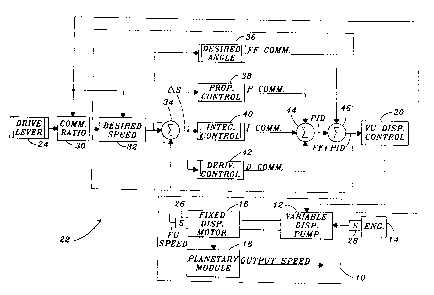
A control system controls a hydrostatic transmission having an engine driven
variable displacement pump coupled to a fixed displacement motor. The pump has
a
swashplate which is controlled by a control signal generated by the control
system.
The control system includes a speed command signal generator, a motor speed
sensor for generating a sensed motor speed signal; an engine speed sensor for
generating an engine speed signal, and a control unit which generates the
control
signal as a function thereof. The control unit generates a desired motor speed
signal as a function of the speed command signal and the engine speed signal,
generates a feed-forward command signal as a function of the desired motor
speed
signal, generates a difference signal as a difference between the desired
motor
speed signal and the sensed motor speed signal; generates an integral signal
by
applying an integral function to the difference signal, generating a sum
signal as a
summation of the feed-forward command signal and the integral signal, and
generating the control signal as a function of the sum signal.

Revendications

Note : Les revendications sont présentées dans la langue officielle dans laquelle elles ont été soumises.


The embodiments of the invention in which an exclusive property or privilege
is
claimed are defined as follow:
1. A control system for controlling a hydrostatic transmission having an
engine driven variable displacement pump coupled to a fixed displacement
motor,
the pump having a swashplate which is controlled by a control signal generated
by
the control system, the control system comprising:
a speed command signal generator;
a motor speed sensor for generating a sensed motor speed signal;
an engine speed sensor for generating an engine speed signal; and
a control unit which generates the control signal as a function of the speed
command signal', the sensed motor speed signal and the engine speed signal,
the
control unit generating a desired motor speed signal as a function of the
speed
command signal and the engine speed signal, generating a desired swashplate
angle signal as a function of the desired motor speed signal, generating a
difference
signal as a difference between the desired motor speed signal and the sensed
motor
speed signal, generating an integral signal by applying an integral function
to the
difference signal; generating a sum signal as a summation of the desired
swashplate
angle signal and the integral signal, and generating the control signal as a
function
of the sum signal.
2. The control system of claim 1, wherein:
the desired swashplate angle signal represents a desired position of the
swashplate of the pump.
3. The control system of claim 1, wherein:
the control unit generates a :proportional signal by applying a proportional
function to the difference signal, generates a derivative signal by applying a
derivative signal to the difference signal, and the control unit generates the
sum
signal as a summation of the desired swashplate angle signal, the proportional
signal, the integral signal and the derivative signal.
4. The control system of claim 3, wherein:

the control unit generates a commanded ratio signal as a function of the
speed command signal and the engine speed signal, and generates the desired
motor speed signal as a function of the commanded ratio signal and the engine
speed signal.
5. The control system of claim 1, wherein:
the control unit generates a commanded ratio signal as a function of the
speed command signal and the engine speed signal, and generates the desired
motor speed signal as a function of the commanded ratio signal and the engine
speed signal.
6. The control system of claim 1, wherein:
the integral function includes a variable gain value; and
the control unit determines the variable gain value as a function of the
difference signal and threshold values.
7. The control system of claim 6, wherein:
the variable gain value is set to a minimum value if the difference signal is
less than or equal to a low threshold value; and
the variable gain value is set to a maximum value if the difference signal is
greater than a high threshold value.
8. The control system of claim 6, wherein:
the variable gain value is set to a variable value if the difference signal is
greater than a low threshold value and less than a high threshold value.
9. A control system for controlling a hydrostatic transmission having an
engine driven variable displacement pump coupled to a fixed displacement
motor,
the pump having a swashplate which is controlled by a control signal generated
by
the control system, the control system comprising:
a speed command signal generator;
a motor speed sensor for generating a sensed motor speed signal;
an engine peed sensor for generating an engine speed signal; and
a control unit which generates the control signal as a function of the speed
command signal, the sensed motor speed signal and the engine speed signal, the
control unit generating a desired motor speed signal as a function of the
speed

command signal and the engine speed signal, generating a desired swashplate
angle signal as a function of the desired motor speed signal, generating a
difference
signal as a difference between the desired motor speed signal and the sensed
motor
speed signal, generating a proportional signal by applying a proportional
function to
the difference signal, generating an integral signal by applying an integral
function to
the difference signal, generating a derivative signal by applying a derivative
function
to the difference signal, generating a um signal as a summation of the desired
swashplate angle signal, the proportional signal, the integral signal and the
derivative signal, and generating the control signal as a function of the sum
signal.
10. A control system for controlling a hydrostatic transmission having an
engine driven variable displacement pump coupled to a fixed displacement
motor,
the pump having a swashplate which is controlled by a control signal generated
by
the control system, the control system comprising:
a speed command signal generator;
a motor speed sensor for generating a sensed motor speed signal;
an engine speed sensor for generating an engine speed signal; and
a control unit which generates the control signal as a function of the speed
command signal, the sensed motor speed signal and the engine speed signal, the
control unit generating a desired motor speed signal as a function of the
speed
command signal and the engine speed signal, generating a desired swashplate
angle signal as a function of the desired motor speed signal, generating a
difference
signal as a difference between the desired motor speed signal and the sensed
motor
speed signal, generating an integral signal by applying an integral function
to the
difference signal, generating a sum signal as a summation of the desired
swashplate
angle signal and the integral signal, and generating the control signal by
applying a
lead-lag function to the sum signal.
11. The control system of claim 10, wherein:
the integral function includes a variable gain value; and
the control unit determines the variable gain value as a function of the
difference signal and threshold values.

12. The control system of claim 11, wherein:
the variable gain value is set to a minimum value if the difference signal is
less than or equal to a low threshold value; and
the variable gain value is set to a maximum value if the difference signal is
greater than a high threshold value.
13. The control system of claim 11, wherein:
the variable gain value is set to a variable value if the difference signal is
greater than a low threshold value and less than a high threshold value.

Description

Note : Les descriptions sont présentées dans la langue officielle dans laquelle elles ont été soumises.


CA 02381918 2002-04-17
CONTROL SYSTEM FOR HYDROSTATIC TRANSMISSION
BACKGROUND OF THE INVENTION v
The present invention relates to a control system for a hydrostatic
transmission.
Infinitely variable transmissions (IVT) include a hydro module having an
engine driven variable displacement pump, or variable unit, and a fixed
displacement
motor, or fixed unit. The variable unit includes a swashplate or yoke which is
pivotal
about a neutral position. The fixed displacement motor or fixed unit may be
connected to vehicle drive wheels through a gear unit and a planetary module.
In
order to accurately control such an iVT, the position of the swashplate must
be
accurately controlled with respect to a speed command signal so that the IVT
output
speed closely matches the commanded speed.1t is also desirable to have an IVT
control system which operates so that he IVT output speed is equally accurate
at
slower speeds and at higher speeds, in both forward and reverse operation.
SUMMARY
Accordingly, an object of this invention is to provide a control system for an
IVT which accurately controls the position of the swashplate with respect to a
speed
command signal.
A further object of he invention is to provide such an IVT control system
which operates so that the IVT output speed closely matches the commanded
speed.
A further object of the invention is to :provide such an IVT control system
which operates so that the IVT output speed is equally accurate at slower
speeds
and at higher speeds, in both forward and reverse operation.
These and other objects are achieved by the present invention; wherein the
hydrostatic module-is controlled by a control system which includes a closed
loop
control algorithm. The control system controls a hydrostatic transmission
having an
engine driven variable displacement pump coupled to a fixed displacement
motor.
The pump has a swashplate which is controlled by a control signal generated by
the
control system. The control system includes a speed command signal generator,
a
motor speed sensor for generating a sensed motor speed signal, an engine speed
sensor for generating an engine speed signal; and a control unit which
generates the
control signal as a function thereof. The control unit generates a desired
motor

z CA 02381918 2002-04-17
speed signal as a function of the speed command signal and the engine speed
signal, generates a feed-forward command signal as a function of the desired
motor
speed signal; generates a difference signal as a difference between the
desired
motor speed signal and the sensed motor speed signal, generates an integral
signal
by applying an integral function to the difference signal, generating a sum
signal as a
summation of the feed-forward command signal and the integral signal and
generating the control signal as a function of the sum signal.
BRIEF DESCRLPTION OF THE DRAWINGS
Fig. 1 is a schematic block diagram of a preferred embodiment of a control
system for a hydrostatic transmission according to the present invention;
Fig. 2 is a schematic diagram of the displacement control unit of Figs. 1 and
5;
Fig. 3 is a logic flow diagram representing an algorithm executed by the
control unit of the present invention;
Fig. 4 is pseudo code representation of a function performed by the control
unit of the present invention; and
Fig. 5 is a schematic block diagram of an alternate embodiment of a control
system for a hydrostatic transmission according to the present invention.
DETAILED DESCRIPTION
Referring to Figs. 1 and 2; a hydrostatic transmission module 1D includes a
variable displacement pump or variable unit 12 which is driven by an engine 14
and
which is coupled to a fixed displacement motor 16. An output of the motor 16
is
coupled to vehicle drive wheels (not shown) via a planetary unit 18: The pump
12
has a yoke or swashplate (shown in Fig. 2) which is controlled by variable
unit
displacement control 20 which receives a control signal generated by control
system
22.
The control system 22 includes a speed command or desired wheel speed
signal generator 24 which is coupled to a shift or gear lever (not
shown),which is
movable fio neutral, park; forward and reverse gear positions. A suitable
speed
command signal generator would be the shiftieverltransducer assembly which is
described in U.S. Pat. No. 5,406,860, issued Apr. 18, 1995 to Easton et al.
The
2

CA 02381918 2002-04-17
speed command signal represents a desired output speed of the transmission
module 10 or speed of the wheels (not shown).
The control system 22 also includes a motor speed sensor 26 which
generates a sensed motor speed signal representing the speed of motor 16 and
an
engine speed sensor 28 which generates a sensed engine speed signal
representing the speed of engine 14. The control system 22 also includes a
commanded ratio unit 30 which determines the operational mode of the
transmission
as a function of the speed command signal and of the sensed engine speed
signal. For example, the transmission 10 may have at least two forward modes
for
slower and faster speeds, and a reverse mode for a range of reverse speeds.
The control system 22 also includes a desired motor speed unit 32 which
calculates a desired speed for the fixed unit 16 based on the engine speed,
the
commanded ratio and mode of transmission operation.
A difference unit 34 generates a difference signal or hydro speed error
signal, ~S, by subtracting the sensed motor speed signal from the desired
motor
speed signal.
A desired variable unit angle calculation unit 36 calculates desired variable
unit angle based on the desired fixed unit speed, mode of transmission
operation,
and maximum and minimum variable unit angle limits in the particular
transmission
mode. This calculated desired variable unit angle is used as a feed-forward
command.
A proportional unit 38 generates a proportional command signal, an integral
unit 40 generates an integral signal; and a derivative unit 42 generates a
derivative
command signal; using known proportional-integral-derivative (PID) techniques
and
variable gain terms as described :later: The outputs of units 38-42 are
combined at
summing unit 44 to produce a PiD signal.
The PID signal is combined with the feed-forward command from unit 36 at
summing unit 46 o produce a combined Feed-forvrvard/PID signal which is
supplied
to displacement control unit 20.
Referring to-Fig. 2, the variable unit displacement control 20 includes a
solenoid operated valve 50 which receives the output signal from summing unit
46 of
3

CA 02381918 2002-04-17
Fig. 1 or from elerr~ent 70 of-Fig. 5. Valve 50 cooperates with displacement
control
spool valve 52 and a pair of servo pistons 54, 56, to control pivot member 58.
Pivot
member 58 is mechanically linked to control the position of the swashplate or
yoke
60 of variable unit 12. A feedback spring 62 provides mechanical feedback
between
the pivot member 58 and valve 52. As a result; a force balance on the control
valve
52 controls the angle of the swashplate 60 of the variable unit 12. One force
is
provided by hydraulic pressure controlled by valve 50: The other force; is
transmitted
from pivot member 58 through feedback spring 62: Alternatively; displacement
control 20 could be an electronic displacement control such as used on
production
John Deere 8000T tractors.
As shown in Figs. 3 and 4; the variable gain terms for functions 36, 38, 40
and 42 are determined. Referring to Fig. 3; the control system 22 executes an
algorithm 100. After starting at step 102, step 104 compares DS to a low error
threshold. If DS is less than or equal to this low threshold, step 110 sets
the gains
for functions 36, 38, 40 and 42 to minimum values and the algorithm ends at
step
114. If OS is greater than this low threshold, the algorithm proceeds to step
106.
Step 106 compares DS to a high error threshold. If DS is less than or equal
to this high threshold, step 112 sets the gains for blocks 36, 38, 40 and 42
according
to a variable gain algorithm represented by the pseudo code listing set forth
in Fig. 4.
If 0S is greater than this high threshold, the algorithm proceeds to step 108.
Step 108 sets the gains for blocks 36, 38, 40 and 42 to maximum values.
The algorithm ends at step 114.
Referring now to Fig. 4, fihe variable gain algorithm represented thereby
generates variable gain values for use by blocks 36-42 of Fig. 1, wherein ~S
is the
hydro speed error, to err is a low threshold value for ~S; hi err is a high
threshold
value for OS, gain_ff is a feed-forward gain term; gain_p is a proportional
gain term,
gain~,l is an integral gain' term, gain d is a derivative gain term, min_gff
is a
minimum value of gain ft, max_gff is a maximum value of gain ff, min_gp is a
minimum value of gain_p, max_gp is a maximum value of gainlp, min_gi is a
minimum value of gain_I, max_gi is a maximum value of gain-I, min_gd is a
4

CA 02381918 2002-04-17
minimum value of gain d; and max_gd is a maximum value of gain d.
As a result of Figs. 3 and 4, the gains for functions 36, 38, 40 and 42 are
set
to minimum values, to maximum values or o variable values, as a function of
the
speed error value OS and as a function of low and high threshold values.
Referring now to Fig. 5, the alternate control system 22A, is similar to the
control system 22 of Fig. 1 with the following differences. In control system
22A the
proportional and derivative units 38 and 42 are eliminated. The feed-forward
command signal from unit 3C is combined with the integral signal from unit 40
at
summing unit 70, and the output of summing unit 70 is supplied to a lead-lag
compensator unit 72. The lead-lag unit 72 generates the control signal
supplied to
the displacement control 20, preferably using conventional pole placement
methods.
The insertion of a lead compensator results in a small increase in gain and
a large increase-in the undamped natural frequency of a control system. The
insertion of a lag compensator in cascade results in a large increase in gain
and a
small reduction in the undamped natural frequency. The lead-lag compensator
unit
72 provides both advantages simultaneously. The large increase in gain
improves
the steady state response, while a large increase in the undamped natural
frequency
improves the transient response. Thus, the system response can be improved
significantly by proper selection of lead and lag compensator components.
Thus, both systems 22 and 22A include a feed-forward signal generating
unit and a integral unit. Both control systems 22 and 22A generate the control
signal
as a function of the speed command signal from 24, the sensed motor speed
signal
from sensor 26 and the engine speed signal from sensor 28.
Thus, the control system 22 operates to position the swashplate 60 of
variable unit 12 at a given angle based on the control signal supplied o the
displacement control 20. The output speed of the fixed unit 16 is therefore a
function of variable unit input shaft speed, swashplate angle (displacement),
loading,
and the efficiencies of both the variable unit 12 and fhe fixed unit 16:
Vllhile the present invention has been described in conjunction with a
specific
embodiment, it is understood that many alternatives, modifications and
variations will
be apparent to those skilled in the art in light of the foregoing description:
For

CA 02381918 2002-04-17
example; the control system described herein could be implemented with a
microprocessor-based control unit executing a computer program. The control
system described herein could be in connection with a hydrostatic transmission
which has two variable displacement pump/motor units instead of one variable
displacement and one fixed displacement unit. The conversion of the above
control
systems into a computer program executed by a digital computer or
microprocessor,
will be evident to one with ordinary skill in the art. Accordingly, this
invention is
intended to embrace all such alternatives, modifications and variations which
fall
within the spirit and scope of the appended claims.
6

Dessin représentatif
Une figure unique qui représente un dessin illustrant l'invention.
États administratifs

2024-08-01 : Dans le cadre de la transition vers les Brevets de nouvelle génération (BNG), la base de données sur les brevets canadiens (BDBC) contient désormais un Historique d'événement plus détaillé, qui reproduit le Journal des événements de notre nouvelle solution interne.

Veuillez noter que les événements débutant par « Inactive : » se réfèrent à des événements qui ne sont plus utilisés dans notre nouvelle solution interne.

Pour une meilleure compréhension de l'état de la demande ou brevet qui figure sur cette page, la rubrique Mise en garde , et les descriptions de Brevet , Historique d'événement , Taxes périodiques et Historique des paiements devraient être consultées.

Historique d'événement

Description Date
Inactive : CIB désactivée 2016-03-12
Inactive : CIB attribuée 2016-01-26
Inactive : CIB enlevée 2016-01-26
Inactive : CIB en 1re position 2016-01-26
Inactive : CIB enlevée 2016-01-26
Inactive : CIB expirée 2010-01-01
Inactive : CIB de MCD 2006-03-12
Inactive : Morte - Taxe finale impayée 2006-02-27
Demande non rétablie avant l'échéance 2006-02-27
Réputée abandonnée - omission de répondre à un avis sur les taxes pour le maintien en état 2005-04-18
Réputée abandonnée - les conditions pour l'octroi - jugée non conforme 2005-02-28
Lettre envoyée 2004-08-26
Un avis d'acceptation est envoyé 2004-08-26
Inactive : Approuvée aux fins d'acceptation (AFA) 2004-08-17
Demande publiée (accessible au public) 2002-12-07
Inactive : Page couverture publiée 2002-12-06
Inactive : CIB en 1re position 2002-07-10
Demande reçue - nationale ordinaire 2002-05-23
Exigences de dépôt - jugé conforme 2002-05-23
Lettre envoyée 2002-05-23
Inactive : Certificat de dépôt - Sans RE (Anglais) 2002-05-23
Exigences pour une requête d'examen - jugée conforme 2002-04-17
Toutes les exigences pour l'examen - jugée conforme 2002-04-17

Historique d'abandonnement

Date d'abandonnement Raison Date de rétablissement
2005-04-18
2005-02-28

Taxes périodiques

Le dernier paiement a été reçu le 2004-04-05

Avis : Si le paiement en totalité n'a pas été reçu au plus tard à la date indiquée, une taxe supplémentaire peut être imposée, soit une des taxes suivantes :

  • taxe de rétablissement ;
  • taxe pour paiement en souffrance ; ou
  • taxe additionnelle pour le renversement d'une péremption réputée.

Les taxes sur les brevets sont ajustées au 1er janvier de chaque année. Les montants ci-dessus sont les montants actuels s'ils sont reçus au plus tard le 31 décembre de l'année en cours.
Veuillez vous référer à la page web des taxes sur les brevets de l'OPIC pour voir tous les montants actuels des taxes.

Historique des taxes

Type de taxes Anniversaire Échéance Date payée
Taxe pour le dépôt - générale 2002-04-17
Enregistrement d'un document 2002-04-17
Requête d'examen - générale 2002-04-17
TM (demande, 2e anniv.) - générale 02 2004-04-19 2004-04-05
Titulaires au dossier

Les titulaires actuels et antérieures au dossier sont affichés en ordre alphabétique.

Titulaires actuels au dossier
DEERE & COMPANY
Titulaires antérieures au dossier
SANJAY ISHVARLAL MISTRY
Les propriétaires antérieurs qui ne figurent pas dans la liste des « Propriétaires au dossier » apparaîtront dans d'autres documents au dossier.
Documents

Pour visionner les fichiers sélectionnés, entrer le code reCAPTCHA :


Pour visualiser une image, cliquer sur un lien dans la colonne description du document. Pour télécharger l'image (les images), cliquer l'une ou plusieurs cases à cocher dans la première colonne et ensuite cliquer sur le bouton "Télécharger sélection en format PDF (archive Zip)" ou le bouton "Télécharger sélection (en un fichier PDF fusionné)".

Liste des documents de brevet publiés et non publiés sur la BDBC .

Si vous avez des difficultés à accéder au contenu, veuillez communiquer avec le Centre de services à la clientèle au 1-866-997-1936, ou envoyer un courriel au Centre de service à la clientèle de l'OPIC.


Description du
Document 
Date
(aaaa-mm-jj) 
Nombre de pages   Taille de l'image (Ko) 
Dessin représentatif 2002-07-10 1 15
Revendications 2002-04-16 4 193
Description 2002-04-16 6 351
Abrégé 2002-04-16 1 37
Dessins 2002-04-16 5 136
Accusé de réception de la requête d'examen 2002-05-22 1 179
Courtoisie - Certificat d'enregistrement (document(s) connexe(s)) 2002-05-22 1 114
Certificat de dépôt (anglais) 2002-05-22 1 165
Rappel de taxe de maintien due 2003-12-17 1 110
Avis du commissaire - Demande jugée acceptable 2004-08-25 1 160
Courtoisie - Lettre d'abandon (AA) 2005-05-08 1 165
Courtoisie - Lettre d'abandon (taxe de maintien en état) 2005-06-12 1 175