Note : Les descriptions sont présentées dans la langue officielle dans laquelle elles ont été soumises.
CA 02382066 2002-02-15
WO 01/13736 PCT/US00/40706
APPARATUS FOR COATING MEAT
Field of the Invention
This invention relates to a method and apparatus for coating meat, such as
with a glazing of melted sugar
and spices, and is particularly useful for glazing hams.
Description of the Related Art
Currently hams may be purchased with a spice coating or glazing. The coating
is applied by sprinkling a
mixture of spices and sugar onto the ham, and using a hand-held blowtorch to
melt the sugar which adheres the spice
to the ham. Repeated applications of coating material and heating are required
to provide a sufficiently thick layer. If
the manual heating is too cool in spots the sugar will not melt and stick to
the ham. If the heating is too hot, the sugar
either burns and becomes very bitter, or it becomes too fluid and runs off the
ham. Further, if too hot, the outer layer
of the meat can burn.
Manual heating and spice application is thus very uneven, and the resulting
coated hams are unevenly coated
with glazing and may have a burnt coating or burnt meat. Manual coating is
also time consuming and expensive, and
results in an inconsistent product.
There is thus a need for a faster way to coat meat such as hams, and to
produce meat with a consistent
coating.
Summary of the Invention
This invention provides a method and apparatus for coating hams. The hams are
moved along a conveyor
path by placing hams on brackets mounted to a conveyor. Sanding sugar is
dispensed from a hopper onto a top
surface of an inclined plate to distribute the sugar uniformly over the plate.
The crystalline sugar is melted by heating
the plate with electric or infrared heaters so the top surface of the plate
melts the sugar without burning the sugar. A
sensor monitors the melting sugar to control the temperature and regulate the
melting by controlling at least one of the
temperature of the plate and the amount of sugar dispensed onto the plate.
Preferably the sensor senses the
temperature of the sugar or a property of the sugar on upper surface of the
plate to generate a control signal
dependent on whether crystalline sugar on the upper surface is melted. The
control signal can be used to vary the
temperature or the amount of sugar on the plate to prevent burning.
The melted sugar is collected in a reservoir placed below the inclined plate
to receive the melted sugar as it
runs off the plate. The melted sugar from the reservoir is placed onto the ham
as the ham moves along the conveyor.
Advantageously, the reservoir rotates to pour the melted sugar onto the ham,
and rotates back for filling.
A spice mixture is dispensed onto the melted sugar on the ham while the melted
sugar is still hot enough to
at least partially melt some of the spice mixture in order to form a glaze.
The spice mixture is preferably placed onto
the melted sugar, but could be placed on the meat before the melted sugar.
Advantageously the glaze is cooled by
directing a cooling fluid into contact with at least one of the melted sugar
and the glaze. The cooling fluid is preferably
a liquid, such as water, but could be other liquids or even a gas. Further,
the ham can be coated by changing the
direction of the conveyor and dispensing a spice mixture onto the glaze and
placing melted sugar from the reservoir
CA 02382066 2005-08-17
onto the ham as the ham moves along the conveyor to form a second layer of
glaze. A controller can
coordinate the various operations, or switches or sensors cooperating with the
conveyor can be used to
control the various operations.
The melted sugar partially melts crystalline sugar in the spice mixture to
provide a glaze with a
non-uniform structure that allows the glaze to break off into small pieces so
the glaze can stick to
smaller pieces of meat. It also provides a glaze that looks like it is custom
applied by hand, and not
applied by a machine. The glaze sticks to the upper surfaces of the meat
because it is applied by gravity
processes, although depending on the viscosity of the melted sugar and spice,
some glaze will adhere
onto sides of the meat. The method and apparatus produce a glazed ham that
looks hand coated, but of
more consistent quality, and better quality, than previously available. It
does so faster, and with less
waste, than hand-coated hams.
According to one aspect of this invention, there is thus advantageously
provided a source of
unburned but melted, crystalline sugar in sufficient amount to coat at least
one piece of meat, and a
reservoir in fluid communication with the source of melted sugar and sized to
contain a sufficient volume
of melted sugar to coat a surface of the at least one piece of meat with the
melted sugar. The reservoir
preferably has at least one hole located to dispense the
melted sugar by gravity onto the meat. A spice dispenser containing spices is
located so as to dispense
the spices over the meat after the meat has been coated with melted sugar. A
jet of water is directed to
cool the melted sugar after it has been placed on the at least one piece of
meat. Also provided is a
conveyor having brackets configured to hold the meat, the conveyor being
configured to move the meat
along a path below the reservoir opening and spice dispenser at least once.
According to one aspect of the present invention, there is provided an
apparatus for coating
meat, comprising:
a conveyor traveling a path in a first direction and having at least one
bracket configured to hold
a piece of meat to be coated;
a reservoir configured to hold melted crystalline sugar, the reservoir having
at least one opening
through which melted sugar can flow to leave the reservoir, the at least one
opening being located
above and over a portion of the conveyor path an amount sufficient to dispense
melted sugar from the
first reservoir onto any meat placed on the brackets as the brackets move
along the path below the at
least one opening;
at least one nozzle in fluid communication with a cooling liquid, the nozzle
being located and
oriented to dispense the cooling liquid onto any meat held by the brackets to
cool the melted sugar from
the reservoir that hits any meat held by the brackets;
a hopper located above and over the conveyor path an amount sufficient to
dispense contents
from the hopper onto any meat held by the brackets, the hopper being located
further along the first
direction than the at least one opening.
Preferably there is also a plate having a heater sufficient to heat the plate
to a temperature
sufficient to melt sugar, the plate having an upper surface onto which
crystalline sugar can be dispensed
for melting, the upper surface being located and inclined to direct sugar
melted by the plate to the
reservoir. It is also desirable to have another hopper located above the plate
and having a first opening
to receive sugar and a second opening to dispense sugar, the second opening
being located above and
-2-
CA 02382066 2005-08-17
over the plate to dispense sugar onto the plate during use of the apparatus.
According to another aspect of the present invention there is provided an
apparatus
for coating meat, comprising:
a conveyor traveling a path in a first direction and having at least one
bracket configured to hold
a piece of meat to be coated;
a plate inclined to the horizontal and having an upper surface facing away
from the
conveyor and a lower surface facing toward the conveyor;
a heater located so as to heat the plate, the location of the heater and a
thickness
of the plate being cooperatively selected to heat the plate to a sufficiently
uniform temperature to melt
sugar placed on the upper surface of the plate so sugar placed on the plate
reaches a flowable state;
a first hopper located above and over the upper surface of the plate so that
sugar
placed in the first hopper can be dispensed onto the upper surface of the
plate for melting by the plate;
a first liquid reservoir in fluid communication with the inclined plate to
receive melted sugar from
the plate, the reservoir having at least one opening through which melted
sugar can flow to leave the
reservoir, the at least one opening being in fluid communication with any meat
placed on the brackets as
the brackets move along the path;
at least one nozzle in fluid communication with a second liquid, the nozzle
being
located and oriented to dispense the second liquid onto any meat held by the
brackets at a location
selected to cool the contents of the reservoir that hit any meat held by the
brackets;
a second hopper located above and over the conveyor path an amount sufficient
to
dispense the contents of the second hopper onto any meat held by the brackets
adjacent the location
that the contents of the reservoir hit any meat held by the brackets.
According to a further aspect of the present invention there is provided an
apparatus
for coating meat, comprising:
a conveyor traveling a path in a first direction and having at least one
bracket configured to hold
a piece of meat to be coated;
a plate inclined to the horizontal at an angle in the range of about 20 to 40
degrees, the plate
having an upper surface facing away from the conveyor and a lower surface
facing toward the conveyor;
a plurality of infrared heaters located below the plate, the heaters being
adjustable
to vary the temperature of the upper surface of the plate within a range
sufficient to melt sugar without
burning it;
a first vibratory hopper located above and over the upper surface of the plate
to
dispense sugar from the first hopper uniformly onto the upper surface of the
plate for melting by the
plate;
a sugar reservoir in fluid communication with the inclined plate to receive
melted
sugar from the plate, the reservoir having a plurality of openings through
which melted sugar can flow to
leave the reservoir, the openings being located above and over a portion of
the conveyor path an
amount sufficient to dispense contents from the first liquid reservoir onto
any meat placed on the
brackets as the brackets move along the path, the reservoir being positionable
between a first filling
position in which melted sugar accumulates in the reservoir and a second
dispensing position in which
melted sugar is dispensed from the reservoir through the plurality of
openings;
-2a-
CA 02382066 2005-08-17
at least one nozzle adapted to be placed in fluid communication with a source
of cooling fluid,
the nozzle being configured and located to dispense a stream of cooling fluid
onto any meat held by the
brackets to cool melted sugar from the reservoir placed on the meat held by
the brackets;
a second vibratory hopper having a dispenser located above and over the
conveyor path to
dispense the contents of the second hopper onto any meat held by the brackets,
the second hopper
being located further along the first direction than the sugar reservoir.
According to still a further aspect of the present invention there is provided
an apparatus for
coating meat, comprising:
a first vibratory hopper for dispensing sugar uniformly over a plate
positioned below the hopper,
a heater in thermal communication with the plate to heat the plate to a
temperature sufficient to melt the
sugar, the heater and plate being in communication with a sensor to regulate
the temperature of the
plate and the amount of sugar dispensed onto the plate to avoid burning the
sugar, a reservoir being in
fluid communication with the plate to receive the melted sugar, the reservoir
having openings through
which melted sugar is dispensed onto the path of a conveyor having brackets
configured to hold meat
for coating, a second vibratory hopper located along the path to dispense
spice onto any meat held by
the brackets, and a nozzle spraying a cooling fluid onto the path at a
location that would cool any melted
sugar placed on meat traveling along the path.
According to yet another aspect of the present invention there is provided an
apparatus for
coating a piece of meat, comprising:
a source of unburned but melted-sugar in sufficient amount to coat at least
one piece of meat;
and
a trough reservoir in fluid communication with the source of melted sugar and
sized to contain a
sufficient volume of melted sugar to coat a surface of the at least one piece
of meat with the melted
sugar, the trough reservoir configured to dispense the melted sugar by gravity
onto the at least one
piece of meat.
According to still yet another aspect of the present invention there is
provided a method for
coating a piece of meat, comprising the steps of:
continuously melting sugar without burning it by applying heat to an inclined
surface on which
the sugar is melted so the sugar runs off the inclined surface;
collecting the melted sugar in a reservoir as the melted sugar runs off the
inclined surface; and
coating the meat as the meat moves along the path by pouring the melted sugar
from the
reservoir onto a top side of the piece of meat.
According to still yet another aspect of the present invention there is
provided a method for
coating hams, comprising the steps of:
moving hams along a conveyor path by placing hams on brackets mounted to a
conveyor;
dispensing sugar from a hopper onto a top surface of an inclined plate to
distribute the sugar
uniformly over the plate;
melting the sugar by heating the plate by heaters so the top surface of the
plate melts the sugar
without burning the sugar;
collecting the sugar in a reservoir placed below the inclined plate to receive
the melted sugar as
it runs off the plate;
-2b-
CA 02382066 2005-08-17
placing the melted sugar from the reservoir onto the ham as the ham moves
along the conveyor
to coat a surface of the ham with melted sugar; and
dispensing a spice mixture onto the melted sugar on the meat while the melted
sugar is still hot
enough to at least partially melt some of the spice mixture to form a glaze.
-2c-
CA 02382066 2002-02-15
WO 01/13736 PCT/US00/40706
Advantageously, the reservoir is positionable between a first receiving
orientation to receive melted sugar
from the plate and a second position to dispense sugar through the at least
one opening. Advantageously, there are
switches or sensors cooperating with the conveyor to change the positioning of
the reservoir between the first and
second positions.
Further, it is also preferable to have a sensor sensing sugar an the upper
surface of the plate to generate a
control signal dependent on whether crystalline sugar on the upper surface is
melted. The signal can be used to vary
the amount of sugar dispensed from the hopper over the plate. Preferably the
sensors in communication with the
melting sugar on the plate provide a signal used to control at least one of
the temperature of the plate and the amount
of sugar placed on the plate for melting.
The plate is preferably inclined to the horizontal and has an upper surface
facing away from the conveyor and
a lower surface facing toward the conveyor. The plate is preferably inclined
to the horizontal at an angle in the range
of about 20 to 40 degrees, with the plate having an upper surface facing away
from the conveyor and a lower surface
facing toward the conveyor
The heater is preferably located so as to heat the plate, the location of the
heater and a thickness of the
plate being cooperatively selected to heat the plate to a sufficiently uniform
temperature to melt sugar placed on the
upper surface of the plate so sugar placed on the heated plate reaches a
flowable state.
There is also provided a method for coating a piece of meat. The method
includes the steps of continuously
melting sugar without burning it by applying heat to an inclined surface on
which the sugar is melted so the sugar runs
off the inclined surface. Preferably, the sugar is sanding sugar. The melted
sugar is collected in a reservoir as the
melted sugar runs off the inclined surface. The meat is coated as it moves
along the path by pouring the melted sugar
from the reservoir onto a top side of the piece of meat. Preferably, the meat
is moved along a conveyor path during
the coating step.
Further, the meat is advantageously coated with a spice mixture containing
granular sugar, either before or
after the sugar coating step by dispensing the spices onto the meat at a
location which contacts the melted sugar, the
melted sugar being hot enough to melt some of the granular sugar on the meat.
Preferably, the spice mixture contains
granular sugar. The method includes the further step of cooling the melted
sugar by placing a cooling liquid into
contact with the melted sugar
Advantageously, the step of melting sugar includes the further step of
regulating the melting of the sugar by
sensing a property of the sugar on the inclined surface and varying at least
one of the temperature or the amount of
sugar placed on the surface. Further embodiments include the step of heating
the reservoir to maintain the melted
sugar in a desired melted condition and may include the further step of moving
the conveyor to pass the piece of meat
at least twice through the melted sugar and spice coating steps.
Brief Description of the Drawings
These and other features and advantages of the invention will become apparent
with respect to the
drawings, in which like numbers refer to like parts throughout, and in which:
-3~
CA 02382066 2002-02-15
WO 01/13736 PCT/US00/40706
FIG. 1 is a plan, side view of the apparatus for coating meat of this
invention.
FIG 2 is a pictorial side view, of the apparatus of Fig. 1 from the opposing
side of FIG. 1.
FIG. 3 is an exploded perspective view of the heaters and heating plate as
used in Fig. 1.
FIG. 4 is a perspective view from one end of a portion of the apparatus of
Fig. 1.
FIG. 5 is a perspective view of a heating plate and reservoir as used in the
apparatus of Fig. 1.
FIG. 6 is a side view of the reservoir of Fig. 5.
FIG. 7 is a perspective view of a portion of the apparatus of Fig. 1.
FIG. 8 is a perspective view of a portion of the apparatus of Fig. 1 showing
the liquid spray.
FIG. 9 is a schematic side view of a drive mechanism for the first hopper and
the heating plate of Fig. 1.
FIGS. 10 -11 are schematics of a control system for the apparatus of Fig. 1.
Detailed Description of the Preferred Embodiment
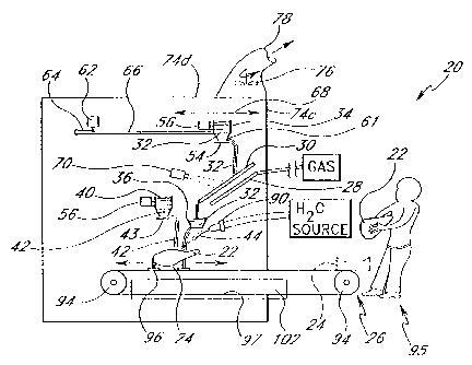
Referring to Figures 1-2, an apparatus 20 is shown for coating a piece of meat
22. For illustration, the meat
22 will be referred to as a ham, although other pieces of meat could be used.
By way of overview, the ham 22 is
placed on racks 24 on a conveyor 26. A heater 28 is located so as to heat an
inclined plate 30 onto which an
unmelted coating substance 32 is dispensed by a first hopper 34 that moves
over the plate 30 to distribute the
unmelted substance 32. Preferably the substance 32 comprises sugar, and it
will be referred to as such.
The sugar 32 melts on the plate 30 and drains off the incline into a reservoir
36. When a sufficient amount
of melted sugar accumulates in reservoir 36, the sugar is dispensed from the
reservoir onto the ham 22. Preferably the
ham 22 passes below the reservoir 36 so that by tipping the reservoir 36 the
melted sugar 32 pours out of the
reservoir 36 onto the ham passing below the reservoir. The conveyor 26
carriers the ham 22 below the reservoir 36.
A second hopper 40 contains a spice mixture combined with the unmelted
substance, e.g., sugar, 32. This
combination of spice and unmelted substance will be referred to as spice
mixture 42. The second hopper 40 dispenses
the spice mixture 42 onto the ham 22 adjacent to the location where the melted
sugar 32 is poured onto the ham so
the melted sugar 32 helps the spice mixture stick to the ham.
Advantageously, a jet of cooling liquid 44, preferably water, is sprayed onto
the ham at the location where
the melted sugar 32, or the spice mixture 42, or both, are placed onto the ham
22. This cools the combination of the
spice mixture 42 and the melted sugar 32 and helps it stay on the ham 22.
Advantageously the conveyor 26 carries the ham 22 through the stations where
the melted sugar 32 and the
spice mixture 42 are each applied, and then reverses direction to pass back
through for another coating of spice
mixture 42 and melted sugar 32. A desired number of such passes can be made
until a desired thickness of coating is
achieved on the ham 22, whereupon the conveyor 26 carries the ham to an
unloading station where the ham is
removed from the conveyor. A more detailed descriptidn of the above described
items is given below.
Melting Apparatus
Referring to Figs. 1-3 and 7, the plate 30 is shown as a flat plate. A plate
about 1 inch (2.5 cm) thick, about
28 inches wide and 30 inches long is believed suitable. The dimensions can
vary depending on the amount of melted
-4-
CA 02382066 2002-02-15
WO 01/13736 PCT/US00/40706
sugar 32 that is needed and the heater that is used. The plate 30 is
advantageously inclined so that as the sugar 32
melts, it runs off a lower end of the plate and into reservoir 36. The angle
will vary with the particular design and the
plate 30 could be horizontal if a mechanism were provided to remove the melted
sugar from the plate. But an angle of
about 20-40° to the horizontal is believed desirable. Advantageously an
angle of about 25-35° degrees, and
preferably about 30° to the horizontal, is believed suitable for the
above described plate 30.
The plate 30 must be heated to a temperature high enough to melt the sugar 32,
but not high enough to burn
the sugar. The plate may be heated by various ways, such as electrical
resistance heating or gas heaters. Electrical
heaters require high voltages and currents that present safety issues for
operating personnel. For the illustrated
embodiment, a gas powered, atmospheric burner, infrared heater 28 is believed
preferable. These heaters resemble
rectangular boxes a few inches thick, with a gas inlet at one end of the
heater. Advantageously three such heaters
28a-c (Fig. 3) are used, each spaced the same distance below the back of the
plate 30 and equally spaced across the
width of the plate 30. Heaters 28a-c are about 60,000 BTU each have been found
suitable. Each of the heaters 28a-c
is normally powered at a constant full-on condition, or off. A valve 50 (Fig.
3) may be installed in the gas line to the
middle heater 28b to shut off the middle heater for temperature control. Of
course ideally, each heater 28a-c could be
separately controllable as to the amount of heat produced in order to better
regulate the temperature of the plate 30.
Referring to Figs. 1-2 and 9, the first hopper 34 holds and dispenses the
unmelted sugar 32 which is
dispensed by gravity down onto the plate 30. The hopper 34 advantageously
holds a large amount of unmelted sugar
32, about five bags, or 250 pounds. The raw, unmelted sugar 32 is preferably
sanding sugar rather than granulated
sugar or confectioners sugar. The bottom of the hopper 34 has a cross-section
that forms a "U" shape, with a slot at
the bottom through which the sugar passes onto a flat or slightly inclined pan
54. One or more vibration units 56 are
mounted on the hopper 34 to shake the sugar 32 from the pan 54 and off a
distal edge of the pan 54 at a controlled
rate. The hopper 34 is about as wide as the plate 30, and has rollers 58 (Fig.
2) connected to opposing ends of the
hopper so the hopper can roll along tracks 60 placed above, and on opposing
sides of, the plate 30. The pan 54 is
about as wide as the plate 30 so as to provide a stream of unmelted sugar 32
from edge to edge across the width of
the plate 30.
The rate at which the sugar 32 flows out of the hopper 34 will vary with the
level of sugar in the hopper 34.
If the hopper is full, the weight of sugar above the opening at the bottom of
the hopper will cause a greater flow rate
than when the hopper is empty. The power to vibration units 56 is preferably
adjusted to compensate for this uneven
flow rate, so that a constant amount of unmelted sugar 32 leaves the hopper 34
and its pan 54. Commercially
available vibration units 56 operating at 60 cycles, with about .05 inch
maximum travel, are believed suitable.
A sensor 61 is placed in the hopper 34 to detect when the hopper is empty. If
the sensor detects an empty
hopper, or a minimum amount of sugar, then an audio andlor visual warning
signal is given. If the hopper 34 runs out
of sugar to put on the plate 30, the plate will overheat and burn the sugar.
Preferably, the heaterls) 28 are shut off if
the level of sugar in the hopper 34 is too low. This can be achieved by a
signal from the sensor 61 to a computer or
-5-
CA 02382066 2002-02-15
WO 01/13736 PCT/US00/40706
programmable logic controller (PLC) 38 to a shut-off valve 114 (Fig. 10) on
the gas line to the heater 28, or a signal
from the sensor 61 directly to the shut off valve.
The hopper 34 is moved over the plate 30 by a drive mechanism. A motor 62 has
a drive shaft connected to
an eccentric 64 to rotate the eccentric 64. The distal end of the eccentric 64
is connected to a first end of linkage 66
with the second end of linkage 66 being connected to hopper 34 so that
rotation of the motor drive shaft and eccentric
64 causes the linkage 66 to reciprocate the hopper 34 along the length of the
plate 30 on tracks 60. Thus, the hopper
34 dispenses unmelted sugar 32 onto plate 30, with the hopper 34 being
reciprocated along the length of the plate 30
to distribute the sugar over the surface of the plate. The length of eccentric
64 is about half the length of plate 30
projected onto a horizontal plane, as reflected in Fig. 9. Arrows 68 in Figs.
1 and 9 indicate this reciprocation.
Advantageously, the eccentric 64 and linkage 66 are selected to cause the
sugar 32 to be dispensed only on the plate
30 to avoid wasting sugar.
The heater 28 heats plate 30, onto which the hopper 34 dispenses unmelted
sugar 32 in order to produce a
source of melted sugar. The heater 28 advantageously heats the plate 30 to a
temperature sufficient to melt the
sugar 32, but not hot enough to burn it, which is difficult to achieve. Sugar
has a high carbon content with a poorly
defined melting point and specific heat. The melting temperature can also vary
with the humidity in the air that is
absorbed by the sugar. It effectively transitions from a solid to a liquid
over a wide temperature range.
Further, if the sugar 32 is placed on the plate 30 unevenly then the melting
sugar will absorb the heat from
the plate unevenly and can result in temperature variations over the plate 30
leading to burning or uneven melting. If
the plate 30 has a hot spot or an uneven amount of sugar 32 on it, the sugar
can burn causing the high carbon content
of sugar to produce an unpleasant taste detrimental to the coating of the ham
22. If the plate gets a cool spot,
unmelted sugar will accumulate or clump, causing melted sugar to flow around
the clump and resulting in an area
downstream of the unmelted clump that is devoid of sugar. That area becomes
hot and leads to burning the sugar. A
similar clumping or caking occurs if the sugar burns. Thus, an even
temperature on the top surface of the plate 30 is
desired along with an even distribution of unmelted sugar 32 to achieve a
constant source of melted but unburned
sugar. The heater 28 is controlled to provide even temperature, and the hopper
34 is controlled to provide a uniform
distribution of sugar 32 uniformly over the plate 30.
Depending on the volume of melted sugar that is desired, various parameters
can be changed. The rate at
which unmelted sugar 32 is dispensed onto the plate 30 can be regulated by the
vibration units) 56 and the incline of
the pan 54. The amount of vibration from vibration units) 56 can be altered by
varying the power to the units) 56,
and is thus more readily adjusted than the incline of the pan 54, which is
typically fixed and not readily altered. The
granularity of the unmelted sugar 32 greatly affects the burning of the sugar,
as the smaller the granules, the more
sensitive the sugar is to burning, and the narrower the permissible
temperature range of the plate 30. Thus, sanding
sugar is used.
The hopper 34 makes one complete back-and-forth pass about every seven seconds
in the specifically
described embodiment. But the rate at which the hopper 34 reciprocates over
the plate 30 can be varied by the
-6-
CA 02382066 2002-02-15
WO 01/13736 PCT/US00/40706
operational speed of motor 62. Moreover, the speed with which the linkage
drive mechanism moves the hopper 34
over the plate 30 varies in a sinusoidal time sequence, with slow speeds and
longer dwell times when the distribution
stream of unmelted sugar 32 is over the ends of the plate 30, and maximum
speed and short dwell times when the
stream of unmelted sugar 32 is over the middle of the plate 30. This will
result in more unmelted sugar being
distributed at the ends of the plate unless something is done to compensate
for the speed variation and unequal
distribution. In practice, it is believed suitable to put a mechanical shut-
off switch so it is hit by the drive linkage 36
each revolution in order to shut off the power to the vibration unitls) 56
about three inches before the end of the
reciprocating stroke in order to decrease the amount of sugar dispensed from
pan 54 onto heating plate 30. Ideally,
the vibration units) 56 are controlled to stop or retard the vibration and
decrease the resulting distribution of unmelted
sugar 32 at the ends of the plate 30. Ideally, the vibration units) 56 are
normally set to provide an even distribution of
unmelted sugar 32 onto the plate 30, which effectively requires a power
distribution in a cosine time sequence. Other
drive mechanisms can be used, and suitable compensation mechanisms or controls
developed in order to distribute
unmelted sugar 32 over the plate 30 in a uniform manner.
Other factors that affect the amount of sugar 30 that is dispensed onto plate
30 are the inclination angle of
the plate 30 and the heat applied by heaters) 28. The greater the amount of
heat applied to plate 30, the hotter the
plate 30, and the greater the amount of sugar 32 that must be supplied to
avoid burning sugar. The greater the angle
of inclination of the plate 30, the faster the melting or melted sugar 32 will
run off the plate 30. Of course the greater
the amount of melted sugar 32, the more pieces of ham 22 that may be coated.
For the specifically described embodiment with the 28 X 30 inch plate at about
30° with three heaters 28
heating the plate 30 to about 480° F, about 3-4 pounds per minute of
melted sugar 32 can be produced. For that
configuration, temperatures from 450° to 500° F are usable, but
temperatures of about 470° to 490° F are safer and
thus preferred. A plate 30 as specifically described, at about 400° F,
will produce about .1 pound of melted sugar per
minute. At 470° F, about 4 pounds per minute of melted sugar will be
produced.
In order to better control the temperature of the plate 30 a temperature
control is preferably used. Various
sensors can be used to monitor either the temperature of the plate 30 or the
sugar 32 as it is melted by the plate.
Advantageously, this temperature control uses sensors 70 to measure the
temperature of sugar 32 or a property of the
sugar 32 melting on the plate 30 which is correlated to temperature of the
melted or melting sugar 32. This is
accomplished by using infrared sensors 70 directed toward the top surface of
plate 30, toward an interior portion of
the plate 30, where raw sugar 32 is melting.
The sensors 70 are advantageously selected to detect the granularity of the
raw, unmelted sugar 32. The
granular sugar 32 reflects more radiation to the detector and indicates a need
to either increase the temperature, or to
slow down the addition of sugar 32. If there are no granules of sugar 32
detected, that indicates melted sugar and the
need to either lower the temperature or the need to add sugar. The detector
can be located various places, but is
advantageously located in the sensor 70 adjacent the IR emitter, in order to
reduce the number of housings for
components. A sensor 70 monitoring about 4 square inches of the plate 30 is
believed suitable. Preferably, there are
.7.
CA 02382066 2002-02-15
WO 01/13736 PCT/(TS00/40706
two sensors 70, at about the middle of the length of the plate 30, each at
about the center of a half-section of the
plate. Other locations and numbers of sensors can be used.
The signal from the sensor 70 is used to control the rate at which unmelted
sugar 32 is added to the plate
30, with more sugar being added as the plate temperature increases, and less
being added as the plate temperature
decreases. The temperature of plate 30 can be controlled by shutting off the
middle burner 28b. The power to the
vibration unitls) 56 can be used to vary the amount of sugar onto the plate
30. The power can be adjusted by a
computer or programmable logic controller (PLC) 38 in response to signals from
sensorls) 70. The computer or PLC 38
can also control the operation of the motor 62 reciprocating the hopper 34,
and the power to the vibration unitlsl 56
to compensate for other system aspects, such as the sinusoidal speed
variation, and the heaters 28.
Advantageously, the sensors) 70 are off during startup, until the temperature
of the plate 30 reaches about
470° F as determined by a thermocouple 71 in the plate 30. The sensors)
70 are set to maintain the flaw of sugar 32
at a predetermined value, depending on the amount of melted sugar 32 desired
and the set point of the burner
temperature controller. Up to this temperature, from about 400°F, the
vibration that determines the amount of sugar
deposited on the plate 30 is determined by the temperature of the plate,
increasing linearly from some minimum level
at about 400°F to a selected value (that is preferably set manually) at
the set point of the temperature controller,
typically about 470°F.
When the sensors 70 take over they seek to maintain a defined level of sugar
on the plate. If too much
melted sugar is on the plate 30, as indicated by too much reflected radiation
from the melted sugar 32, then signals
from the sensors 70 are used to reduce the vibration of vibration units 56 and
pan 54 causing less sugar to be
dispensed onto plate 30. Conversely, if too little sugar is detected by
sensors 70, the vibration is increased causing
more granulated sugar to be dispensed onto plate 30. The temperature of the
heaters 28 are preferably set to
maintain the temperature of the plate at about 470°F and the amount of
sugar is controlled to prevent burning or too
much unmelted sugar, rather than varying the temperature to prevent burning or
to melt sugar faster.
If, for some reason, too little sugar falls onto the plate 30, the sugar can
boil, producing bubbles that reflect
radiation and can be mis-read as granules of sugar that require either less
sugar or more heat - just the opposite of
what is needed. Thus, the sensor 70 must be calibrated relative to the
condition of the melted or melting sugar 32,
and calibrated relative to temperature. But the temperature of plate 30 is
advantageously controlled so the sugar 32
does not bubble as it melts, thus avoiding the problem. Limiting the
temperature to about 490° F as determined by the
sensor 70, is believed desirable to avoid boiling.
The sensors 70 are advantageously mounted to a frame 72 around and supporting
the plate 30.
Advantageously the sides and back of the plate 30 and heaters 28 are enclosed
by side walls 74a-b and back wall 74c
to enclose the heat from plate 30 and burners 28, and to prevent people from
getting burned. Preferably at least a
portion of the top over the plate 30 is also enclosed by top wall 74d. The top
wall 74d must allow for movement of
the reciprocating first hopper 34, so all of the top cannot be enclosed. But
advantageously the remaining area
vertically above a majority, if not all of the plate 30, is covered by top
wall 74d.
.g.
CA 02382066 2002-02-15
WO 01/13736 PCT/US00/40706
A fan 76 (Fig. 1) in fluid communication with the enclosure surrounding the
plate 30, draws heated air and
gases out of the enclosure and vents the exhaust gas through appropriate
environmental filters (not shown) to the
atmosphere. The fan 76 is also preferably in fluid communication with the
exhaust from heaters) 28 to exhaust the
fumes from the burners. If the fan 76 is strong enough, then a smaller top
wall 74d is suitable. Advantageously, the
fan 76 is located vertically above the back portion of the plate 30 to exhaust
gases from the inclined plate 30 and the
heaters) 28. The enclosure formed by frame 72 and sides 74a-d advantageously
forms an enclosure that helps
exhaust gases through fan 76 and vent 78.
There is thus advantageously provided a means for providing a constant source
of melted sugar which
basically comprises a heated plate, at least one mechanism for distributing
sugar evenly over at least a portion of the
plate (multiple sugar dispensers can be used on a single platel, and a
temperature control for preventing burning of the
melted sugar on the plate. Advantageously about 3-4 pounds per minute of
melted sugar 32 are produced, with the
amount being variable depending on the number of hams 22 to be glazed.
Reservoir
The melted sugar 32 flows by gravity off the plate 30, into reservoir 36.
Referring to Figs. 1-2 and 5-7, the
reservoir 36 comprises an elongated trough or container having an open top
through which the melted sugar 32 is
received as it flows off the plate 30. Through holes or openings 80 in the
reservoir 36, melted sugar 32 flows onto
hams 22 as the hams pass below the openings 80. Referring to Fig. 6, the
reservoir 36 has four sides 36a-d, with an
open top. The reservoir 36 has enclosed ends 36 e-f to form an enclosed
container with an open top formed between
sides 36a and 36d. The sides 36a and 36d are opposite to each other and
generally parallel, with the interior sides
36b and 36c being angled so they abut at an angle, preferably of about
60°, with sides 36a and 36d joining the sides
36b and 36c, respectively, also at about 60°. If you added two more
sides the container 36 would form a hexagon in
cross-section with each side about 3 inches wide. The reservoir 36 needs to be
long enough to receive the melted
sugar from the plate 30.
The ends 36e-f are rotatably mounted so they can pivot or rotate about a
horizontal axis along the length of
the reservoir 36, through pivots 82 on each of the ends 36e-f. Openings 80 are
formed in side 36b, adjacent the
juncture with side 36a. The openings 80 are located relative to the pivot axis
through pivots 82 so that in a first, fill
orientation they are located at or above the pivot axis 82 to retain the
contents of reservoir 36, and in a second, pour
orientation they are located below the pivot axis 82 to dispense the contents
of the reservoir 36.
In this configuration, the reservoir 36 always has an opening 83 through which
melted sugar 32 can flow
into the reservoir, and it has openings 80 through which melted sugar 32 can
be poured onto the hams 22 when
desired. Advantageously, the melted sugar 32 accumulates in the reservoir 36
until the level of the sugar 32 reaches
the bottom of the holes 30, at which point the reservoir is rotated into its
second, pour orientation to pour the melted
sugar onto the hams 22 as they pass below the openings 80. The reservoir 36 is
then rotated into the first, till
orientation to accumulate additional melted sugar. In the depicted
configuration, there is about 60° of rotation about
the axis through pivots 82, between the fill position and the pour position.
-9-
CA 02382066 2002-02-15
WO 01/13736 PCT/US00/40706
Referring to Fig. 8, the openings 80 are located vertically above the location
of the hams 22 as they pass
below the openings, so that melted sugar 32 can flow by gravity out of the
openings 80 onto the hams 22 when the
reservoir 36 is rotated to the second, pour position. The size of the hams 22,
and the location of the hams 22 on the
carriers 24 of conveyor 26 will vary. Thus, the number, size and location of
the openings 80 can vary.
Advantageously, four openings 80 are used for each ham 122, with the openings
comprising circular holes about 318
inch (.375 in.) diameter, and with about two inches between centers of the
holes 80. In the specifically described
embodiment, two hams 122 are carried side-by-side on the conveyor 26, so there
are eight openings 80, to produce
aligned streams of melted sugar 32 perpendicular to the path of conveyor 26.
The two sets of four openings 80, are
separated by about 4 inches, to allow for some spacing between adjacent hams
22.
The reservoir 36 is preferably made of stainless sheet steel, or other
materials compatible with handling
edible, melted sugar at up to 500° F. Advantageously, a heater, such as
resistance heater 84 (Fig. 61, is placed on the
reservoir 36 to maintain the temperature of the melted sugar 32. Further,
during startup, the heater 84 can ensure
that any partially melted sugar reaching the reservoir 36 is further melted.
Advantageously the heater 84 is placed on
the side 36b, adjacent the openings 80, to ensure heating by the dispensing
holes to melt any clumps of unmelted
sugar and to keep the openings 80 unclogged.
A thermocouple 86 is advantageously spaced inward from the free edge of the
wall 36d to measure and
control the temperature of the reservoir 36 to be about 340°F. It is
possible to place a sensor on the reservoir 36 to
indicate the level of the melted sugar in the reservoir 36. To achieve such a
liquid level measurement, a sensor is
advantageously placed slightly below (about'/z inch) the horizontal plane
through the bottom of the openings 80 when
the reservoir 36 is in the fill position, as shown in Fig. 6.
Advantageously, the reservoir 36 is made to oscillate, side-to-side, through a
stroke of about one inch (2.5
cm) at a rate of about 124 cycles per minute. This forms undulating streams of
melted sugar when in the pouring
position, and help disperse the melted sugar on the meat being coated. As
conceptually shown in Fig. 5, an offset
linkage mechanism 91 mounted on the frame and driven by motor 89 can be used
to cause the oscillation.
A motor 88 (Fig. 8) is mounted to frame 72 and connected to one of the ends
36e-f to rotate the reservoir
36. The rotation is controlled by the computer or PLC 38 or by switches on the
conveyor 26 or by sensors on or by
the conveyor 26. The electrical connection to the resistance heater 84 is
achieved by using a slip ring.
Advantageously, the slip ring accommodates lateral movement along the
rotational axis through pivots 82, as well as
accommodating rotational movement. The electrical connection at the pivots 82
also provides electrical
communication to the thermocouplels) 86. An electrical connection sold by
Mercotac is believed suitable for the
specifically described embodiment.
The reservoir 36 will pour one or more streams of melted sugar 32 onto the
hams 22. The temperature of
the melted sugar 32, the size and location of the openings 80 relative to the
ham 22, are preferably selected to retain
as much of the melted sugar on the ham as possible. The melted sugar 32 that
runs off the ham 22 is waste, that
collects in one or more drip containers 102 (Fig. 8) placed below the conveyor
26.
10-
CA 02382066 2002-02-15
WO 01/13736 PCT/US00/40706
A direct flow path for the sugar 32 from the melting plate 30 to reservoir 36
is thus provided by placing the
reservoir 36 directly below the plate 30 and having an opening of the
reservoir always available to receive flow from
the plate. An indirect flow path could be used in which a channel or tube (not
shown) guides flow from the plate 30 to
a location for dispensing the melted sugar over the hams 22, but the direct
flow is preferred.
There is thus provided means for continuously receiving melted sugar from the
plate 30, means for
dispensing melted sugar 32 onto the ham 22 and means for varying the amount of
melted sugar that is dispensed.
Spice Dispenser
Referring to Figs. 1-2, 7, and 9-10, the sugar and spice mixture 42 is
contained in second hopper 40 having
parallel side walls connected to a converging, funnel-like bottom that ends in
a slot extending roughly the length of the
hopper. A second dispensing pan 43 is placed below this slot. The second pan
43 could be horizontal, but is preferably
slightly inclined to allow the mixture 42 to flow off a free end of the plate
onto the hams 22 travelling below the plate.
One or more vibration units 56 control the flow of the spice mixture 42 off
the pan 43. The edge of the pan 43, off
which the spice mixture 42 is dispensed, is preferably of sufficient length to
dispense the mixture onto the hams 22 to
be coated. It can be slightly shorter if the spice stream disperses on contact
with the ham 22. A pan 43 about 15
inches long is believed suitable for coating two nested hams 22.
Advantageously a sensor 46 (Fig. 7) is located in the second hopper 40 to
monitor the level of the spice
mixture 42. If the level drops too low, an audio andlor visual warning is
given so the hopper can be refilled.
Preferably, if the level drops too low, the system will be shut down in a
manner similar to that achieved by sensor 61
on the first hopper 34 as discussed above.
The location of the stream of dispensed spice mixture 42 can vary, but it is
preferably close enough to the
streams of melted sugar 32 that the spice mixture 42 will adhere to the melted
sugar 32 and remain on the ham 22.
The mixture 42 that falls off the ham 22 is waste that collects in one or more
drip containers 102 placed below the
conveyor 26. Further, to avoid waste, the vibration units 56 on the second
hopper 40 are controlled by the computer
or PLC 38 or by switches on the conveyor 36, so that the spice mixture 42 is
dispensed only when the hams 22 on
conveyor 26 are positioned to receive the spice mixture. For the specifically
described embodiment, dispensing the
spice mixture 42 at about .8-10 pounds per minute is believed suitable.
The spice mixture 42 will vary with the meat to be coated. Preferably the
mixture contains granules of sugar
of sufficient size that not all of the granules melt completely during the
coating process. The unmelted granules give
an uneven variation to the glaze, and cause the glaze to break into uneven
size pieces. If the glaze is of uniform
thickness of completely melted sugar then it will break off in large chunks so
that each sliced piece of meat will not
have any glaze on it. The variation caused by unmelted granules allows each
sliced piece of meat to retain a portion of
the glaze. A mixture of 48 ounces of spice with 50 pounds of confectioners
sanding sugar is used with the specifically
described embodiment.
The type of sugar used is believed to affect the performance of the coating.
The sugar is preferably
confectioners sanding sugar. Such sugar purchased from California and Hawaiian
Sugar Co., Inc. in California has
.11.
CA 02382066 2002-02-15
WO 01/13736 PCT/US00/40706
been successfully used. It has a color (1000aS4201 of 9 maximum, with a grain
size (U.S. series) of 25% maximum on
U.S. 20, and 6% maximum thru U.S. 40. It is 99.98% sugar, with about 0.015 %
moisture. The average color is 6,
and the average grain size is 12.7 % US 20, 48.6% US 30, 36% US 40, 2.4% US 50
and .3% thru US 50.
The type and mixture of spices used will vary widely, depending in part on the
meat to be coated and the
particular taste to be imparted. A spice using varying portions of sugar and
other spices is believed suitable. The
composition of the spice will vary according to taste. The composition of the
spice is not believed to be important, but
the fact that the spice is mixed with granulated sugar when dispensed onto the
meat is important. One particular
spice found useful for coating ham includes a mixture of the following items,
listed in order of weight: sugar, gelatin,
honey powder (honey, high fructose corn syrup, wheat starch, corn syrup, soy
flour), paprika, dextrose, spices and
natural flavorings.
There is thus provided means for dispensing powdered spice onto the ham 22 and
means for varying the
amount of spice dispensed.
Cooling Fluid
Referring to Figs. 1 and 8, one or more jets of cooling fluid 44 are sprayed
onto the ham 22 to help the
melted sugar 32 and the spice mixture 42 stay on the ham 22. Preferably, a jet
of cooling liquid 44, such as water, is
located below, and aligned with, each of the openings 80 in reservoir 36. This
requires placement of nozzles 90 to
spray each jet of liquid 44. Preferably, the cooling fluid 44 is a liquid, and
more preferably it is water, although other
liquids could be used, such as spiced or flavored water, or a liquid
sweetener. Further, the cooling fluid 44 could be a
gas although the gas is less preferable because it does not cool as fast as a
liquid of the same temperature. The
nozzles 90 are placed in fluid communication with a source of fluid and
pressurized to a desired pressure, by means
known in the art and not described herein.
While separate nozzles 90 with separate pressurization pumps for one or more
nozzles could be used,
advantageously the nozzles 90 comprise a pipe with a series of holes
orientated to spray the ham 22. The pipe is
preferably perpendicular to the path of conveyor 26. Holes about 1116 inch in
diameter on a quarter inch water line at
60 psi, are believed suitable, with the water at the local environmental
temperature. Preferably, the cooling fluid 44 is
not at a high enough pressure to force melted sugar 32 or the spice mixture 42
off the ham 22. Various changes in the
sources of the cooling fluid 44, in the temperature of the fluid, and in the
location and configuration of the nozzles 90
can be made depending on the meat to be coated and the goal of coating the
glaze to reduce runoff.
The streams) of cooling fluid 44 are directed so as to increase the amount of
glaze remaining on the ham 22.
The glaze comprises the melted sugar 32 and the spice mixture 42. Preferably,
the melted sugar 32 melts some of the
sugar in the spice mixture 42, but does not completely melt all of it. If the
spice mixture 42 contains granular spice
that melts with the melted sugar 32, that should also work to provide a glaze
that breaks into small pieces so as to
adhere to each slice of ham.
The spray of cooling fluid 44 is directed toward a location on the ham 22 in
the area where the mixture 42
and the melted sugar 32 hit the ham. The spray of the fluid 44 is controlled
by the computer or PLC 38 or by switches
.12.
CA 02382066 2002-02-15
WO 01/13736 PCT/US00/40706
on the conveyor 26, so that it begins shortly after the melted sugar 32 hits
the ham 22. A .2 second delay is believed
suitable. This cools the melt and reduces run-off in order to increase the
amount of sugar and spice retained on the
ham 22. The spray of cooling fluid 44 is preferably shut off when pouring of
the melted sugar 32 is stopped, but the
spray could continue to be used to cool the glaze if desired. The timing and
location of the application of the cooling
fluid 44 can vary.
There is thus provided means for cooling the glaze to increase the amount of
glaze remaining on the ham 22.
Conveyor
Referring to Figs. 1-2 and 4, the conveyor 26 is configured to carry the hams
22 through the locations where
the ham is coated with melted sugar 32 and with spice 42 in order to glaze the
ham. A straight conveyor that changes
direction is believed suitable, and offers some advantages but other conveyors
could be used. The conveyor 26 has a
pair of sprockets 94 at each end, about 12 inches in diameter, with the
sprockets 94 being joined by axles to
synchronize the sprocket rotation. A conveyor 26 about eight feet between
sprockets 94 is believed suitable,
providing for a very compact glazing machine.
Each sprocket 96 engages an endless chain 97 to which are fastened cross-bars
94. The racks 24 that hold
the hams 22 are connected to the cross-bars. The racks 24 will vary in shape
with the meat to be held. For ham 22,
the racks 24 are rectangular strips that have a length along the length of the
conveyor and a shorter width extending
vertically, and that have a curved recess cut into the rectangle on the upper
side. Each rack 24 in a pair of racks are
spaced apart about 4-5 inches. The curves are sized to hold a whole ham 22
that is placed on a pair of racks 24.
Advantageously the racks 24 are angled at an angle of about 30° to a
line across the conveyor that is aligned with the
rotational axes of the sprockets 94.
Advantageously four racks 24 are placed in line across a width of the conveyor
26. A ham 22 is placed on
each pair of racks 24. To reduce waste the hams 22 are preferably orientated
so occupy as much of a given area as
possible. Thus, the ham 22 on one rack 24 is nested with the thick end
adjacent a narrow end of the ham on the
adjacent rack 24.
The conveyor 26 has a first, loading end 95 that projects beyond the heater 28
and is accessible by one or
more workers who manually place the hams 22 on the racks 24. A second, distal
end of the conveyor 26 is located
beyond the second hopper 34. Drive sprocket 98 on one of the shafts connecting
two of the sprockets 96 is driven by
a reversible motor 100 (Fig. 4) to rotate the conveyor 96 in either direction
along the length of the conveyor 26. A .25
hp, 40 RPM gear motor 100 with an effective gear reduction of about 6:1 drives
the sprockets 96 and conveyor 26.
Below the path of the conveyor 26 are placed one or more drip containers 102
that extend the length of the
conveyor 26 is traveled by the hams 22. The containers 102 collect the melted
sugar 32, mixture 42 and cooling fluid
44 that does not stick to the hams 22. The contents of the drip containers may
be recycled to recover some of the
contents, but it cannot be reused to coat hams 22.
Preferably, a mechanical limit switch 132 (Fig. 11) is used to limit the
motion of the conveyor 26. By placing
a projection on one of the chains 97 located to hit an electrical contact on
frame 72 around the conveyor 26, the
-13-
CA 02382066 2002-02-15
WO 01/13736 PCT/US00/40706
motor 100 can be controlled to stop the conveyor 26 when the racks 24 are at
the first, loading end. Similarly, a limit
switch having a projection on one of the chains 97 located to hit a different
electrical contact on the frame 72 around
the conveyor 26 can be used to stop the conveyor when the racks 24 are at the
distal end of the conveyor and to
reverse the direction of the conveyor and move the racks 24 toward the loading
end. Various other projections on the
chains 97 cooperating with switches on frame 72 can be used to activate and
deactivate various components.
Similarly, position sensors on frame 72 detecting the position of racks 24 or
meat 22 could be used. While a single,
reversible conveyor is shown, other conveyor configurations can be used, such
as a continuous circle or a longer
conveyor with multiple coating stations. Similarly, electronic controls or
computer controls can be used instead of
mechanical limit stops.
There is thus provided means for conveying meat along a predetermined path.
Operation
The operation will be described using a combination of mechanical limit
switches and PLC 38 controls to
regulate various components. Because the relative locations and geometry of
the conveyor 26, racks 24, reservoir 36,
the second hopper 40 and the cooling fluids 44 are known, it is possible to
use mechanical or electrical switches on
the conveyor to control the timing and operation of the reservoir to dispense
melted sugar, of the second hopper to
dispense spice mixture 42, and of the cooling jets 44 to cool the glaze and
reduce run-off. It is also possible to use
position sensors detecting the position of rack 24 to activate these
components. It is also possible to control the
operation of these components by the PLC 38. Thus, the control of the above
components in the sequence given
below can be varied by the PLC 38 or by various switches actuated by the
conveyor 26 or sensors activated by the
racks 24 or ham 22 or other markers on the conveyor 26.
The heaters 28 are turned on to heat plate 30. A thermocouple in the plate 30
monitors the temperature and
sends a signal correlated to the temperature to the PLC 38. When the
temperature reaches about 400° F, the first
hopper 34 begins reciprocating and dispensing sugar onto the plate 30. At
470°F or whatever the set point of the
heater controller, the temperature control is then switched to sensor 70. The
heater 84 on the reservoir 36 is
activated at the time the Blazer is turned on and set to maintain a
temperature of about 340°F. Melted and partially
melted sugar 32 flows off the plate 30 into reservoir 36, where the heater 84
further melts any unmelted sugar 32.
The sensors 70 in cooperation with the PLC 38 control the hopper 34 to provide
uniform distribution of sugar 32 onto
the plate 30 at a rate that leads to continued melting of sugar without
burning.
A worker has manually placed a whole ham 22 onto each of the two racks 24.
When a condition of full
reservoir 36 with proper fluidizing of the melted sugar 30 is observed, the
worker presses an activation button which
signals the PLC 38 to move the conveyor 26 by activating motor 100 to rotate
drive sprocket 96, sprockets 94 and
chain 97. This provides a manual, visual inspection before starting the
glazing machine. Alternatively, an automatic
conveyor which reads the signal could directly activate motor 100. The ham 22
is moved at a speed corresponding to
about 90% maximum motor power until the ham is just below the reservoir 36, at
which time the PLC 38 slows the
conveyor 26 down to a speed corresponding to about 50% motor power.
-14-
CA 02382066 2002-02-15
WO 01/13736 PCT/US00/40706
As the ham 22 passes below the reservoir 36, the PLC 38 or a switch on
conveyor 26 or a position sensor
causes motor 88 to rotate the reservoir causing melted sugar 32 to flow out
openings 80 down onto the ham 22. The
PLC 38 or another switch on conveyor 26 causes motor 88 to rotate the
reservoir 36 back to the fill position when the
ham is past the pour location. The timing preferably accounts for the time it
takes the melted sugar 32 to leave the
reservoir and reach the ham 22 in order to reduce waste.
Shortly after the melted sugar 32 hits the ham 22 the PLC 38 or a switch on
conveyor 26 or a position
sensor causes the cooling fluid 44 to be sprayed onto the ham in order to cool
the melted sugar and reduce run-off. A
delay of about .2 seconds is believed suitable. Shortly after the melted sugar
32 hits the ham 22 the PLC 38 or a
switch on conveyor 26 or a position sensor activates the second hopper 40 and
its vibration unit 56 to dispense the
spice mixture 42, so the mixture hits the ham just as or slightly before the
portion covered by melted sugar passes
below the hopper 40. The spice mixture 42 sticks to the melted sugar 32 to
form a first layer of glaze on the ham 22.
The PLC 38 or another switch on conveyor 26 or another position sensor gives a
signal that shuts off the hopper 40
and its vibration unit 56 so the stream of spice mixture 42 stops just about
the time the ham 22 passes by in order to
avoid wasting the mixture 42. The melted sugar 32 and mixture 42 that does not
remain on the ham 22 falls through
and below the conveyor 26 into drip containerls) 102.
At this point, the PLC 38 or a limit switch on chain 97 stops the motion of
conveyor 26, and reverses it,
sending a signal to the PLC 38. The glazed ham 22 now moves in the opposite
direction for another coating.
As the ham 22 passes below the hopper 34 for the second time, the PLC 38, a
switch on conveyor 26 or a
sensor activates the hopper and its vibration unit 56 to cause spice mixture
42 to be dispensed onto the ham 22 just
as it passes below the dispensed mixture 42, the spice mixture sticking to the
first coating of glaze on the ham. The
PLC 38, a switch on conveyor 26 or a sensor also rotates the reservoir 36 so
that melted sugar hits the ham and
entrains the spice mixture 42 onto the ham to form a second layer of glaze on
the ham 22. The cooling fluid 44 is also
activated by the PLC 38 or a switch on the conveyor 26 or a position sensor to
cool the glaze. The PLC 38 or a switch
on the conveyor 26 or a position sensor stops the dispensation of the spice
mixture 42 and stops dispensation of the
melted sugar 32 when they will no longer hit the ham 22. The cooling fluid 44
is also shut off by the PLC 38, a switch
on the conveyor or a position sensor about the time the melted sugar 32 is
shut off.
The coating sequence is preferably repeated again to provide four layers of
glaze on the ham 22. To do this,
each time the racks 24 reach the distal end of the conveyor 26, a signal is
sent to the PLC 38 which counts the
number of passes and controls the number of coatings applied. But the number
of times through the coating sequence
can be varied as desired. It is believed desirable to have about 1.25 - 1.5
pounds of glazing for each whole ham 22.
After the desired number of glazings are applied, the conveyor 26 moves the
racks 24 to the loading station 95 where
the hams 22 are manually removed. The sequence may then be repeated after a
green light illuminates, following a
sufficient delay for the reservoir to refill.
The coating is very fast, taking only 3-4 seconds to pour the melted sugar 32
onto ham 22. The oscillation
of the reservoir 32 causing the streams of melted sugar 32 to oscillate
improves the dispersion of the sugar over the
-15-
CA 02382066 2002-02-15
WO 01/13736 PCT/US00/40706
meat and improves coating. The plate 30 produces a rapid stream of melted
sugar 32, and the reservoir 36 may be
rapidly refilled to provide further coatings. Alternatively, additional
reservoirs could be provided or a larger reservoir
with openings that are actively opened and closed could be used.
Controls
A schematic of the basic control system is shown in Figures 10-11. A switch
110 activates the coating
apparatus. Upon activation of the switch 110, the burner temperature
controller 112 activates the heaters 28a-28c.
The controller 112 receives a signal from thermocouple 71 in the plate 30
indicative of the plate temperature. When
the temperature as reflected by thermocouple 71 reaches a predetermined value,
preferably about 400°F, the
controller 112 activates the sugar hopper motor 62 which begins the
oscillation of the hopper 34 across the plate 30.
Advantageously, at the same temperature the controller 112 also activates the
reservoir oscillator motor 56 that
begins oscillation of the reservoir 36 and activates the heater 84 on the
reservoir. Based on the signal from the
thermocouple 71, at a predetermined set point, preferably about 470°F,
the controller 112 will deactivate one or more
of the burners 28a-28c to limit the temperature of the plate 30. Preferably
the middle burner 28b is deactivated by
shutting off valve 50. Other heaters could be controlled, and if desired one
or more heaters could be partially
deactivated to vary the heat produced by one or more of the heaters. The
controller 112 also controls a main gas shut
off valve 114 to stop heating entirely in the event the need arises, such as
the hoppers 34 running out of sugar.
Activation of the on-off switch 110 also activates the sugar temperature
controller 116, which also receives
signals from thermocouple 71 in plate 30. The sugar controller 116 activates
the vibratory motors 56 on hopper 34 to
dispense sugar onto plate 30 at a predetermined temperature, preferably in the
range of about 400-450°F, based on
the signal from the thermocouple 71. When the temperature of plate 30 reaches
a predetermined temperature,
preferably about 470°F, a change-over control relay 118 switches
control of the vibratory motors 56 from the
controller 116 to a signal processor 120 which receives input signals from
sensors 70 indicative of the temperature of
the melted sugar on the plate 30. The signal processor 120 then varies the
vibratory motors 56 to vary the amount of
sugar dispensed onto the plate 30. The controller 112, change-over relay 118
and signal processor 120 are preferably
located in and comprise part of the programmable logic controller (PLCI 38.
Figure 11 shows a basic control system by which the PLC 38 activates the
conveyor 26 and other
components. The PLC 38 controls the operation of the vibration motors 56 on
hoppers 34 and 40 to dispense sugar
32 and spice mixture 42, and also controls the cooling liquid dispensed
through nozzles 90. An on-off switch 130
adjacent the conveyor 26 sends a signal to the PLC 38 to activate or stop the
conveyor 26 depending on the signal the
PLC 38 sends to motor 100 that drives the conveyor. Mechanical limit switches
132 comprising projections or pegs
on the conveyor 26 or conveyor chain 97 cooperating with sensors on the frame
72 adjacent the projections or pegs
are used to coordinate the activation of devices based on the position of the
conveyor and meat 22 placed at known
locations on the conveyor. Thus, the limit switches 132a can be used to rotate
the reservoir 36 when the ham 22 is
physically below reservoir 36 to dispense melted sugar onto the ham, and to
rotate the reservoir into a non-dispensing
position when the ham has past. This is achieved, for example, when a peg is
located on the chain 97 adjacent the
-16-
CA 02382066 2002-02-15
WO 01/13736 PCT/US00/40706
position of a ham 22 placed on the conveyor, with the peg hitting and
activating an electrical switch to cause the
reservoir 36 to rotate. Similarly, limit switch 132b can reverse the motor 100
and cause the conveyor 26 to change
direction. Likewise, limit switch 132c can stop the conveyor motor 100 and
stop conveyor 26 when the ham 22 is at
the unloading station (Fig. 1). Of course, other types of switches and sensors
can be used to activate various
components of the equipment based on the position of the ham 22 or the racks
24. Such other sensors include
proximity sensors, optical sensors, capacitance sensors etc. But mechanical
switches are simple and reliable and thus
preferred.
The above description is given by way of example, and not limitation. Given
the above disclosure, one skilled
in the art could devise variations that are within the scope and spirit of the
invention, including various ways of
controlling the sequence of events or of arranging the coating components like
the hoppers 34, 40, reservoir 36 and
cooling streams 44, relative to the conveyor 26 and ham 22. Further, the
various features of this invention can be
used alone, or in varying combinations with each other and are not intended to
be limited to the specific combination
described herein. Thus, the method and apparatus for melting sugar has
separate application for other uses. The
invention is not to be limited by the illustrated embodiments but is to be
defined by the following claims when read in
the broadest reasonable manner to preserve the validity of the claims
.17.