Note : Les descriptions sont présentées dans la langue officielle dans laquelle elles ont été soumises.
CA 02382079 2002-02-13
WO 01/13151 PCT/US00/19252
SEGMENTED THIN FILM ADD/DROP SWITCH AND MULTIPLEXER
CROSS-REFERENCE TO RELATED APPLICATIONS
This Application claims the benefit of priority under 35 U.S.C. ~ 119(e) for
U.S.
Provisional Patent Application Serial No. 60/148,862 filed on August 13, 1999,
the
content of which is relied upon and incorporated herein by reference in its
entirety.
BACKGROUND OF THE INVENTION
1. Field of the Invention
The present invention relates generally to optical switches, and particularly
to an
optical switch using thin film filters.
2. Technical Background
Wavelength Add/Drop Multiplexers (WADMs) are currently gaining
considerable attention in the development of communication systems because of
the
flexibility, capacity, and transparency they provide. WADMs allow service
providers to
efficiently reconfigure networks to meet changing service requirements. This
is
especially helpful in metropolitan area applications because it provides the
capability of
adding and dropping communication payloads at each node in the communication
ring.
WADMs also provide the same capability for long-distance applications. At any
local
node, wavelength channels that are destined for the local node are directed
into a drop
port and integrated with local traffic. Other wavelength channels which are
merely
passing through the node remain undisturbed. Thus, switching is performed in
the
CA 02382079 2002-02-13
WO 01/13151 PCT/US00/19252
2
optical domain, and the inefficiencies associated with optical to electrical
domain
conversion are avoided.
In order to exploit the full capability of optical domain switching, WADMs
must be reconfigurable and wavelength channel selectable. These two attributes
enable
service providers to allocate bandwidth on demand and redistribute wavelengths
where
required in an optical network. Most current technologies allow an add/drop
node to be
reconfigured; however, only a few provide full reconfigurability and channel
selectability without interrupting adjacent channels.
There are several issues that need to be addressed before the capacity of WDM
systems can be increased. Obviously, the ability to use more of the available
spectrum
is one way to increase capacity. One way to accomplish this is by increasing
the
number of wavelength channels in the system by reducing the spacing between
channels. However, this problem is compounded by the need for broad band
channels
that carry more information.
It has been proposed to increase the flexibility of the channel shape by
differentially heating a fiber Bragg grating from one end to another. This
allowed the
grating to be chirped, expanding its reflected spectrum. By controlling the
absolute
temperature, the shape of the center of the channel could be manipulated.
While this
flexibility is impressive, it has a major drawback. It requires significant
monitoring and
control functionality to be added to the component to make it useful.
Additionally, this
device is an 'analog' type device. It will have a tendency to drift with time
and
temperature.
This points out a need for a WDM switch that flexibly selects individual
wavelength channels in a system, whereby wavelength channels are flexibly
allocated
within the communications system.
SUMMARY OF THE INVENTION
The WDM switch and WADM of the present invention provides flexible
selection and allocation of wavelength channels with a WDM communications
system.
The switch and WADM use a channel selector for wavelength channel selection.
The
channel selector is composed of multiple single channel filter elements and a
highly
reflecting mirror that covers the wavelength range of interest. The channel
selector also
CA 02382079 2002-02-13
WO 01/13151 PCT/US00/19252
3
provides the ability to band pass filter the optical signal. The band pass
filter can be
selected for either wide band or narrow band operation depending on the
requirements
of channel spacing.
One aspect of the present invention is an optical device for directing the
light
signal having a plurality of wavelength channels. The optical device includes
a
wavelength selector segment that includes a plurality of filters corresponding
to the
plurality of wavelength channels; and a reflector segment disposed adjacent to
the
plurality of filters.
Another aspect of the invention is an optical device for directing a light
signal
having N-wavelength channels, wherein N is an integer. The optical device
includes
an input port for directing the light signal into the optical device. N-
channel selectors
are coupled to the input port, each of the channel selectors includes a
wavelength
selector segment having a filter corresponding to a wavelength channel of the
N-
wavelength channels, and a reflector segment disposed adjacent the wavelength
selector
segment. The optical device also includes N-drop ports, each drop port of the
N-drop
ports is coupled to a corresponding channel selector whereby a selected
wavelength
channel is directed into a drop port when the light signal is incident a
wavelength
selector segment corresponding to the selected wavelength. An output port is
coupled
to the N-channel selectors whereby the light signal is directed out of the
optical device.
Another aspect of the invention is a method of directing a light signal having
a
plurality of wavelength channels. The method includes the steps of providing
an
optical device having a wavelength selector segment that includes a plurality
of filters
corresponding to the plurality of wavelength channels, and a reflector segment
disposed
adjacent the plurality of filters, whereby the light signal is incident the
reflector segment
causing substantially all of the light signals to be reflected. A wavelength
channel is
selected by moving the optical device in a first direction, such that the
light signal is
incident a first filter of the plurality of filters, whereby a first
wavelength channel
propagates through the wavelength selector segment and other wavelength
channels of
the plurality of wavelength channels are reflected.
Another aspect of the invention is a method for directing a light signal
having a
plurality of wavelength channels along an optical path in an optical device.
The optical
device includes an input port for directing a light signal into the optical
device, a drop port
CA 02382079 2002-02-13
WO 01/13151 PCT/US00/19252
4
for removing the selected wavelength channel from the light signal, and an
output port for
directing the light signal out of the optical device. The method includes the
steps of
providing a segmented channel selector having a wavelength selector segment
and a
reflector segment disposed adjacent to the wavelength selector segment,
whereby the light
signal is incident the reflector segment causing the light signal to be
reflected into the
output port. The channel selector is moved relative to the optical path such
that the light
signal is incident the wavelength selector whereby the selected wavelength
channel passes
through the wavelength selector segment into the drop port and other
wavelength channels
of the plurality of wavelength channels are reflected into the output port.
Additional features and advantages of the invention will be set forth in the
detailed description which follows, and in part will be readily apparent to
those skilled
in the art from that description or recognized by practicing the invention as
described
herein, including the detailed description which follows, the claims, as well
as the
appended drawings.
It is to be understood that both the foregoing general description and the
following detailed description are merely exemplary of the invention, and are
intended
to provide an overview or framework for understanding the nature and character
of the
invention as it is claimed. The accompanying drawings are included to provide
a
further understanding of the invention, and are incorporated in and constitute
a part of
this specification. The drawings illustrate various embodiments of the
invention, and
together with the description serve to explain the principles and operation of
the
invention.
BRIEF DESCRIPTION OF THE DRAWINGS
Figure 1 is a diagram of the segmented channel selector according to a first
embodiment;
Figure 2 is a diagram of the segmented channel selector according to a first
embodiment showing channel selection;
Figure 3 is a linearly variable channel selector according to a second
embodiment;
Figure 4 is a diagram of a channel selector having a bandpass filter in
accordance with a third embodiment;
CA 02382079 2002-02-13
WO 01/13151 PCT/US00/19252
Figure 5 is a is a diagram of a channel selector and bandpass filter in
accordance
with a fifth embodiment ;
Figure 6 is a method of manufacturing a thin film channel selector;
Figure 7 is an alternate method of manufacturing a thin film channel selector;
5 Figure 8 is a plan view of a switch incorporating the channel selector
disclosed
in the fifth embodiment of the present invention;
Figure 9 is a diagram of an WADM switch using the channel selector of the
fifth
embodiment of the present invention;
Figure 10 is a diagram view of a flexure arm and chuck in the mechanical
implementation of the switch and WADM depicted in Figures 8 and 9;
Figure 11 is a diagram view of a chuck assembly used to implement the switch
and WADM depicted in Figures 8 and 9;
Figure 12 is a detail view of a switch actuator used to actuate the flexure
arm
depicted in Figure 10;
Figure 13 is a detail view of a thrust bearing used in the chuck assembly
depicted in Figure 10;
Figure 14 is a graph comparing switching losses for a damped switch and a
switch that has not been damped; and
Figure 15 is a diagram of an alternate chuck assembly used to implement the
switch and WADM depicted in Figures 8 and 9.
DETAILED DESCRIPTION OF THE PREFERRED EMBODIMENTS
Reference will now be made in detail to the present preferred embodiments of
the invention, examples of which are illustrated in the accompanying drawings.
Wherever possible, the same reference numbers will be used throughout the
drawings to
refer to the same or like parts. An exemplary embodiment of the Channel
selector of
the present invention is shown in Figure 1, and is designated generally
throughout by
reference numeral 10.
In accordance with the invention, the present invention for an optical switch
or
WADM 1 includes a channel selector 10. Channel selector 10 may include
multiple
single channel filter elements and a highly reflecting mirror that covers the
wavelength
range of interest. When implemented in an optical switch apparatus or a WADM,
the
CA 02382079 2002-02-13
WO 01/13151 PCT/US00/19252
6
channel selector 10 is movable in two orthogonal degrees of motion, making the
switch
or WADM channel selectable and reconfigurable without impacting adjacent
channels.
These features provide many advantages that are not found in conventional
add/drop
switch technologies. The present invention has low optical loss. The light
signal is not
filtered by tuning-through adjacent filters when changing wavelength channels.
As a
result, there is no cross-talk due to "tuning-through." The channel selector
has low
non-uniformity, is small in size, and integrated. The switches and WADMs that
incorporate the channel selector are reconfigurable, and provide latching
switch states.
The basic design of the WADM or switch is a two-channel module. The two-
channel
modules can be cascaded to add/drop N-wavelengths, where N is an integer.
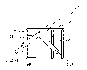
As embodied herein and depicted in Figure 1, channel selector 10 according to
a
first embodiment of the present invention is disclosed. Channel selector 10
includes
wavelength selector 100 and a reflector segment 110. Wavelength selector
segment100
is an array of discrete wavelength channel filters 102-108, which each passing
a
spectral band corresponding to a wavelength channel. As shown, filter segment
102
transmits wavelength channel ~,1 and reflects all other wavelength channels,
in this case,
wavelength channels ~,2 and ~,3.
As embodied herein and depicted in Fig. 2, wavelength channel selection in
accordance with the present invention is disclosed. As shown, channel selector
10 is
moved with respect to the optical beam to select a desired wavelength channel.
In this
example, channel selector 10 is reconfigured from passing wavelength channel
~,1 to
passing wavelength channel ~,~. One salient feature of the present invention
is that
reflector segment 110 is disposed adjacent to all channel filters 102-108. The
arrangement of filter elements 102 -108 allows for channel selection
capability without
"tuning through" adjacent channels. Channel selector 10 is initially
positioned such
that wavelength channel ~,1 is selected by illuminating element 102. By moving
filter
switch 10 with respect to the incident beam to the high reflector, all of the
wavelength
channels are reflected. The selection of another channel is effected by moving
channel
selector 10 such that the relative movement of the beam is along reflector
segment 110
until the beam is positioned adjacent to the selected filter 108. Channel
selector 10 is
then moved to position the optical beam onto the selected filter 108.
CA 02382079 2002-02-13
WO 01/13151 PCT/US00/19252
7
Since individual channel selectors access a different portion of the system
spectrum, one of ordinary skill in the art will recognize that multiple
channel selectors
can be cascaded in a WADM or switch device. A set of four channel selectors
10, each
having four different channel filters can be used to access any channel in a
16
wavelength channel system.
As embodied herein and depicted in Figure 3, a linearly variable channel
selector 10 is disclosed in accordance with a second embodiment of the present
invention. One of ordinary skill in the art will recognize that by moving
linearly
variable filter 100 as shown, channel selector 10 can be tuned to any center
wavelength.
When incorporated into an optical switch or WADM, a tunable optical switch or
WADM is created.
As embodied herein, and depicted in Figure 4, a channel selector 10 having two
band
pass filter segments, A1 and A2, is disclosed in accordance with a third
embodiment of
the present invention. Wavelength selector segment 100 includes filter segment
114 that
is tuned to wavelength channel A1 and filter segment 116 that is tuned to
wavelength
channel A2. Wavelength channels A1 and A2 are both tuned to the same
wavelength
channel. However, filter segment 114 (A 1 ) has a narrow pass band, whereas
filter
segment 116 (A2) has a broad pass band. In this instance, channel A1 has a 50
Ghz
pass-band and channel A2 has a 100 GHz pass band. During the switching motion,
the
switch moves from reflector segment 110 to filter segment 114 to thereby
provide a 50
GHz pass band. Systems using 50 Ghz wide channels typically separate adjacent
channels by 0.4 nm. If channel A were to be configured as a 100 GHz wide
channel,
then the switch would move through Al to A2. Systems using 100 GHz channel
widths
typically separate adjacent channels by 0.8 nm. One of ordinary skill in the
art will
recognize that moving channel selector 10 through A1 has no effect on any
adjacent
channels. As channel selector 10 settles into A2, there is no impact on
adjacent
channels.
As embodied herein and depicted in Figure 5, a channel selector 10 having two
wavelength channel filters each including two-pass bands is disclosed in
accordance
with a fourth embodiment of the present invention. Wavelength selector segment
100
includes filter sub-segment 114 (A 1 ), filter sub-segment 116 (A2), filter
sub-segment
119 (B 1 ), and filter sub-segment 120 (B2). Filter sub-segment 114 passes
wavelength
CA 02382079 2002-02-13
WO 01/13151 PCT/US00/19252
8
channel A with a 50 GHz pass band. Filter sub-segment 116 passes wavelength
channel A and has a 100 GHz pass band. Filter sub-segment 118 passes
wavelength
channel B and has a 50 GHz pass band. Filter sub-segment 120 passes wavelength
channel B and has a 100 GHz pass band. Sub-segments 114,116, 118, and 120, are
interleaved allowing channel selector 10 to shift from reflector segment 110
to sub-
segments 114, 116, 118, or 120 directly. By interleaving the sub-segments, the
light
beam is directed onto the desired segment only, without the intermediate step
associated
with the channel selector 10 depicted in Figure 4. One of ordinary skill in
the art will
recognize that channel selector 10 can be implemented having a circular shape.
Channel selector 10 can also be implemented to move in a circular motion as
needed.
As embodied herein and depicted in Figure 6, a method of manufacturing
channel selector 10 is disclosed. First, substrate 130 is formed. Substrate
130 is
masked using a photolithographic technique. Alternatively, it is cut into
strips and
masked mechanically before being coated with the reflector segment material.
Reflector segment 110 may be of any suitable type, but there is shown by way
of
example a reflective metallic material. One of ordinary skill in the art will
recognize
that a dielectric material may also be used to fabricate reflector segment
110. Second,
the broader spectral filter segment 116 is deposited on reflector segment 110.
Subsequently, segment 116 is masked. The narrower filter segment 114 is then
deposited over the unmasked portion of segment 116. Finally, broad band filter
segment 116 and narrow band filter segment 114 are masked and a high
reflective
coating such as a gold film is applied to reflector segment 110. The thickness
of the
gold film must be chosen appropriately to achieve high reflectance and
minimize
interference effects. It is noted that the switch will suffer small transient
losses during
switching from the effects of scattering at the gold film edge. However, the
area of the
edge is small compared to the area of the beam, and hence, the scattering
losses are
inconsequential. One of ordinary skill in the art will appreciate that each
filter segment
is matched in phase to adjacent filter segments.
As embodied herein and depicted in Figure 7, an alternate method of
manufacturing channel selector 10 is disclosed. Layers of thin-films
representing
segments 110, 114, and 116 are directly deposited onto substrate 130. A
CA 02382079 2002-02-13
WO 01/13151 PCT/US00/19252
9
photolithographic masking process is used to ensure that segments 110, 114,
and 116
are perfectly matched at the interfaces.
As embodied herein and depicted in Figure 8, a two-channel drop switch 1 is
disclosed. Switch 1 includes input port 20 which directs a light signal toward
drop port
26. Channel selector 100 is disposed between input port 20 and drop port 26
and
reflects the light signal toward drop port 22. Channel selector 200 is
disposed between
channel selector 100 and drop port 22 and ultimately, reflects the light
signal toward
output port 24.
Input port 20, drop ports 22 and 26, and output port 24 may be of any suitable
type, but there is shown by way of example an optical fiber connected to a
GRIN lens or
any other suitable collimator.
Channel selectors 100 and 200 may be of any suitable type, but there is shown
by way of example in the detail view of Figure 8, channel selectors consisting
of a
single segment wavelength selector 102 (202) and a reflector segment 110 (210)
in
accordance with a fifth embodiment. Wavelength selector 102 passes wavelength
channel ~,1 and reflects all other wavelength channels. Wavelength selector
202 passes
wavelength channel ~,Z and reflects all other wavelength channels.
Switch 1 operates as follows. Switch 1 independently moves channel selectors
100 and 200 in the direction A-A perpendicular to the optical beam to achieve
switching. The relative motion of the beam with respect to the filter is shown
in the
detail view of Figure 8. For example, when channel selector 100 is positioned
to have
the beam incident filter segment 102, wavelength channel 7~, is resonant with
the thin
film filter segment 102, and wavelength channel ~,I passes through channel
selector 100
into drop port 26. The remaining channels are uniformly reflected from filter
segment
and directed toward channel selector 200. In similar fashion, if the incident
beam is
positioned on filter segment 202, wavelength channel 7~2 passes through
channel selector
200 into drop port 22. The remaining channels are directed by channel
selectors 100
and 200 into output port 24. Switch 1 is reconfigured by moving either, or
both channel
selectors 100 and 200 to position the beam on reflecting segments 110 or 210,
as
desired. When the light signal is incident reflecting segments 110 or 210, all
channels
are uniformly reflected into output port 24. Thus, either ~,~ or 7~2, or both,
can be
dropped or included in the output signal directed into output port 24.
CA 02382079 2002-02-13
WO 01/13151 PCT/US00/19252
One of ordinary skill in the art will recognize that switch 1 shown in Figure
8
can be converted into an add/drop switch by providing an add port for each
drop port
provided. Furthermore, switch 1 in Figure 8 can be cascaded to accommodate
more
wavelength channels.
5 As embodied herein and depicted in Figure 9, a WADM 1 using the channel
selectors shown in Figure 8 is disclosed. Input port 20 directs the light
signal into
WADM 1, toward channel selector 100, which selectively filters wavelength
channel
~,~. As discussed above, when reflector segment 110 (Figure 8) is in the path
of the
light beam, all wavelength channels are reflected toward channel selector 200
(~,2). If
10 the light signal is incident filter segment 102, wavelength channel ~,1 is
directed into
drop port 26. At the same time, add port 34 directs add channel ~,~ into WADM
1
through the opposite side of filter segment 102 and add channel 7~~ is
inserted into the
outgoing optical beam toward channel selector 200 (~,2 ). As depicted, channel
selector
200 is optically coupled to channel selector 3000,3 ). Depending on the
position of
channel selector 300, wavelength channel ~,3 can be dropped into drop port 28
and a
corresponding add channel can be added via add port 38. Channel selector 300
is
optically coupled to channel selector 400 (~,N ). Again, depending on the
position of
channel selector 400, wavelength channel ~,N can be dropped into drop port 30
and a
corresponding add channel can be added via add port 36. Finally, the output
light
signal reflects off channel selector 400 into output port 24. Channel
selectors 100-400
are actuated independently. Thus, an N-stage cascaded device can independently
drop
or add N-wavelength channels. One of ordinary skill in the art will recognize
that other
channel selector configurations (see Figures 2-5) can be used depending on
system
needs.
As embodied herein and depicted in Figure 10, a perspective view of switch l,
showing mechanical actuation details is disclosed. Flexure arms 50 and 60 are
used to
actuate channel selectors 100-400 in the switch and WADM depicted in Figures 8
and
9, respectively. Channel selector 100 is mounted in chuck 52 on flexure arm
50.
Channel selector 200 is mounted in chuck 62 on flexure arm 60. Flexure
structures 54
and 64 provide fme angular adjustments as well as coarse angular adjustments
with two
degrees of freedom. Flexure structure 54 in flexure arm 50 provides an angle
adjustment in the horizontal plane and flexure structure 64 in flexure arm 60
provides
CA 02382079 2002-02-13
WO 01/13151 PCT/US00/19252
11
angular adjustments in the vertical plane. Angular adjustments are achieved by
inserting a proper tool into slot to bend the flexures in either direction.
The size of the
deforming flexure member in each flexure 54 and 64 is chosen to provide
adequate
mechanical strength in combination with adequate deformability by the special
tooling.
These angular adjustments provided by flexures 54 and 64 allow channel
selectors 100
and 200 to be aligned to each other within 20 arc seconds (100 micro-radians).
Flexure
arms 50 and 60 also include indented regions 588 and 688, respectively. These
regions
are provided to accomodate thrust bearings 58 and 68, respectively. Flexure
arms 50
and 60 also include holes 586 and 686, respectively. Holes 586 and 588 are
used to
accommodate a connector or screw (not shown) which acts as a pivot or axle.
The
screw is co-linear with the axis of rotation. This arrangement will be
discussed in more
detail below.
As embodied herein and depicted in Figure 11, a perspective view of chuck
assembly 70 is disclosed in accordance with the present invention. The switch
1
disclosed in Figure 8 is housed by base plate 72. The various compartments
formed in
base plate 72 were formed by a machining process to accommodate collimators
20, 22,
24, and 26, solenoids 56 and 66, and flexure arm assemblies 50 and 60 depicted
in
Figure 10. One of ordinary skill in the art will recognize that it is a
relatively simple
task to produce more compartments in a larger block of aluminum when
implementing
the WADM depicted in Figure 9.
In one embodiment of the chuck assembly depicted in Figure 11, flexure arms
50 and 60 are movable with one degree of freedom. Thrust bearing assemblies 58
and
68 are formed around flexure arms 50 and 60 and are attached to base plate
support 74.
Thrust bearings 58 and 68 are fastened with a spring-loaded connector on base
plate
support 74 to form a pivot co-linear with the axis of rotation. Thrust
bearings 58 and 68
limit the movement of flexure arms 50 and 60 in directions orthogonal to the
direction
of rotational motion. Channel Selectors 100 and 200 are mounted to chucks 52
and 62,
which are indented regions formed at the ends of flexure arms 50 and 60,
respectively.
Flexure arms 50 and 60 are rotatable around the axis of rotation and move
channel
selectors 100 and 200 between two or more positions in switch l, depending on
the
type of channel selectors used (See Figures 2-S). Actuators 56 and 66 are
coupled to
flexure arms 50 and 60, respectively. Actuators 56 and 66 actuate the flexure
arms
CA 02382079 2002-02-13
WO 01/13151 PCT/US00/19252
12
causing them to rotate about the rotational axis within a range of 4 degrees
to obtain the
channel selector functions discussed above for adding or dropping a wavelength
channel. In another embodiment, two-degrees of freedom can be incorporated
into
switch 1 by mounting two mini slides (not shown) under thrust bearing
assemblies 58
and 68. In this embodiment, base plate 70 is machined to accommodate two
additional
solenoids for actuating the two mini-slides.
Actuators 56 and 66 may be of any suitable type, but there is shown by way of
example magnetic latching bi-state solenoids. One of ordinary skill in the art
will
recognize that a commercially available latching relay is also be suitable.
As embodied herein and depicted in Figure 12, a detail view of the actuation
mechanism of flexure arms 50 and 60 is disclosed. The description relates to
flexure
arm 50, but one of ordinary skill in the art will recognize that the
description is equally
applicable to flexure arm 60 as well. Flexure arm 50 includes holes 566 and
568 which
accommodate damping springs 562 and 564. Plunger 560 of solenoid 56 pushes
damping leaf spring 560 toward flexure arm 50. Arm 562 of damping leaf spring
560 is
disposed in hole 566 and acts to push flexure arm 50 downward. This downward
movement causes flexure arm 50 to rotate around the axis of rotation, to
thereby move
channel selector 200 (Figure 11 ) into position. Damping spring 564 is
connected to
base plate support 74 and is inserted into hole 568. Spring 564 resists the
downward
movement of flexure arm 50 and supplies a damping resistance that mitigates
unwanted
vibrations that would otherwise result in fitter.
As embodied herein and depicted in Figure 13, a detail view of thrust bearing
assembly 58 is disclosed. One of ordinary skill in the art will recognize that
the
description is equally applicable to thrust bearing assembly 68. As discussed
above,
flexure arm 50 includes indented regions 588 which are disposed about hole
586.
Thrust bearings 584 fit within indented regions 588. Screw 580 is disposed in
holes
586 and 686. As discussed above, flexure arm 50 and thrust bearings 584 rotate
around
screw 580 allowing 4° of movement between switch positions. Screw 580
presses
against wave washer 582 and thrust bearings 584 to form spring loaded thrust
bearing
assembly 58. Screw 580 applies approximately 4 1b. of force to thrust bearings
584.
This force substantially eliminates channel selector jittering during
rotational
movement. Thrust bearing assembly 58 exceeds the vibration/shock requirement
set by
CA 02382079 2002-02-13
WO 01/13151 PCT/US00/19252
13
Bellcore standards. The thrust bearings 584 used in assembly 58 are designed
for
rotation of 500 rpm (revolution per min) with a long lifetime. Thus, the
design is
durable and reliable. Any wearing that does occur will be compensated for by
the
spring-loading mechanism 582.
Figure 14 is a plot showing the improvement in transient excess loss due to
the
use of thrust bearing assemblies 58 and 68 discussed above. The plot
represents the
excess loss that is generated in neighboring wavelength channels when flexure
arm 50
is actuated to move channel selector 100 to drop wavelength channel ~,1. Curve
300
shows actuation of wavelength channel 7~1. As shown by curve 304, wavelength
channel ~,3 experiences significant vibrations without the damping provided by
thrust
bearing assembly 58. This results in transient excess-loss greater than lSdB
for a
maximum duration of 100msec. As shown by curve 306, wavelength channel ~,3
experiences less than 0.5 dB excess loss with the damping provided by thrust
bearing
assembly 58. Note that with the damping, the excess loss occurs within the
lOmsec
switch actuation time.
As embodied herein and depicted in Figure 15, a diagram of an alternate chuck
assembly 80 is disclosed. Channel selector 100 is disposed and glued into
chuck 52.
Chuck 52 is an indented region formed at one end of flexure arm 50. Channel
selector
200 is disposed and glued into chuck 62. Chuck 62 is an indented region formed
at one
end of flexure arm 60. Flexure arms 50 and 60 are connected to Schneeberger
micro-
frictionless slides 70 and 90, respectively. Slides 70 and 90 provide a very
smooth
motion with a deviation from the plane of motion of under 2 microns. Slide 70
is
indirectly connected to solenoid 56 via spring 74 and arm 50. Slide 90 is
indirectly
connected to solenoid 66 via spring 94 and arm 60. Flexure arm 50 is connected
to a
second spring 72, whereas flexure arm 60 is connected to spring 92. Springs 72
and 92
act as a loading force on linear slides 70 by being bolted onto flexure arms
50 and 60,
respectively. This arrangement ensures a smoother motion. Flexure arm 50 is
mounted
onto flexure member 54, which has a motion horizontal to the beam path.
Flexure arm
60 is mounted on flexure member 64, which has a motion perpendicular to the
beam
path. This arrangement is very similar to the first mechanical implementation
discussed
above. Flexure members 54 and 64 provide a means for ensuring beam
parallellism,
and tuning the incident angle of the light beam onto channel selectors 100 and
200.
CA 02382079 2002-02-13
WO 01/13151 14 PCT/US00/19252
~ mug, mC yv ucpmcu m r yure 14 is applicable to the cnucK assemmy or r figure
1 ~, as
well.
Solenoids 56 and 66 are magnetic latching, bi-state solenoids. For example,
magnets 560 are provided at either end of solenoid 56. Solenoid 66 is also
equipped
with magnets 660. Solenoids 56 and 66 are encapsulated in a vibration
absorbing foam
which further serves to mitigate the effects of vibration on transient excess
loss.
Springs 74 and 94 serve to absorb vibrations inherent in the switching motion
of
solenoids 56 and 66. Springs 72 and 92 oppose the motion of solenoids 56 and
66,
respectively. Vibrations are reduced by slowing down the motion of the
solenoid at the
end of the stroke. Thus, vibrations are further damped, and a smooth return
force is
ensured when the solenoids retract.
It will be apparent to those skilled in the art that various modifications and
variations can be made to the present invention without departing from the
spirit and
scope of the invention. Thus, it is intended that the present invention cover
the
modifications and variations of this invention provided they come within the
scope of
the appended claims and their equivalents.