Note : Les descriptions sont présentées dans la langue officielle dans laquelle elles ont été soumises.
CA 02382565 2002-02-20
WO 01/16639 PCT/US00/24247
AUTOMATIC ALIGNMENT SYSTEM FOR COUPLING MULTIPLE
LIGHT SOURCES
CROSS-REFERENCES TO RELATED APPLICATIONS
This application claims the benefit of priority under 35 U.S.C. ~ 119 from
U.S. Provisional Patent Application Serial No. 60/151,704 filed on August 31,
1999, the
disclosure of which is hereby incorporated by reference in its entirety for
all purposes.
BACKGROUND OF THE INVENTION
Research and development efforts over the past couple of decades have led
to the commercial realization of relatively low-cost, low-loss optical fibers.
In many
industries, such as biomedical instrumentation and telecommunications, optical
fibers
have become the preferred choice of transmission medium.
A variety of equipment exploiting the benefits of optical fibers have been
1 S developed over the years. For example, due to their small size, optical
fibers are now
commonly utilized in various types of medical instruments to help reduce the
invasive
nature of surgical or other medical procedures. In the telecommunications
field, a
number of telephone companies are revamping or otherwise rebuilding their
communication systems and networks to take advantage of the benefits, such as
compact
size and high transmission speed and capacity, offered by optical fibers.
Generally, optical fibers are used to transmit light emitted from a light
source to a destination. Optical fibers are usually encapsulated in a
fiberoptic cable. The
light emitted from the light source represents one or more signals. The
transmitted light
is received at the destination and then deciphered to identify the intended
signals. For a
relatively short distance, one integral segment of fiberoptic cable can be
used to transmit
the light from the light source to the destination. However, for a number of
practical
considerations, such as signal strength degradation, scalability, and
maintainability, etc.,
disjoint pieces of fiberoptic cables coupled together by optical couplers are
typically used
to transmit the light from the light source to the destination. Inevitably, a
certain amount
of coupling loss is incurred when optical couplers are used to couple disjoint
segments of
fiberoptic cables.
Despite the advances made in the fiber optics field, coupling losses or
coupling e~ciency in fiberoptic cables have remained a major topic of
interests for
CA 02382565 2002-02-20
WO 01/16639 PCT/US00/24247
engineers and researchers alike. Coupling losses may be caused by alignment
errors, as
well as a number of other factors including reflections at glass-air
interfaces, poor fiber-
end quality, and mismatches between the parameters of the fibers being
coupled.
Coupling losses resulting from alignment errors are a particularly acute
problem for fiberoptic cables due to the minuscule size of the individual
optical fibers.
The diameter of an optical fiber is generally in the range of 10-200 microns.
To put it in a
more tangible context, this quantity is usually no greater than the diameter
of a strand of
human hair. Due to this minuscule size, it is self evident that the problem of
aligning
fiberoptic cables, in particular, the optical fibers, to achieve optimal
transmission
efficiency is a particularly challenging one.
Alignment errors are generally caused by mechanical imperfections in the
jointing techniques. Such imperfections include separation between the fiber
ends,
relative lateral displacement of the core axes, and angular misalignment of
the fiber axes.
On a conceptual level, these errors can be easily identified. The apparent
solution appears
deceptively simple and straightforward -- all that is required seems to be the
accurate
mechanical alignment of the optical fibers. However, due to the microscopic
size of the
optical fibers and the mechanical nature of alignment, these errors in most
cases are
actually immensely difficult to correct. Thus, it would be desirable to
provide a system
that is capable of optimizing the coupling efficiency and conversely
minimizing the
coupling loss of connected fiberoptic cables.
Moreover, for new and old equipment alike, calibration or alignment of the
fiberoptic cables need to be performed initially before use and periodically
thereafter to
ensure that the accuracy of the equipment stays within tolerable levels. Under
most of the
currently existing industry practices, the mechanical alignment is manually
performed by
a field technician with the aid of certain calibration equipment.
Consequently, this
manual approach often requires a substantial amount of time for the technician
to
complete the necessary procedures. Hence, it would be desirable to provide a
system that
is capable of correcting alignment errors without human intervention and in a
time
efficient manner.
Furthermore, as a consequence of the difficult nature in resolving the
alignment problem, the cost of remedying such problem has become
proportionally
expensive. As previously mentioned, in order to correctly align two optical
fibers (to
within tolerable levels of accuracy), current conventional practices require a
field
-2-
CA 02382565 2002-02-20
WO 01/16639 PCT/US00/24247
technician to be present on site to perform the mechanical alignment manually.
Needless
to say, this necessarily incurs substantial expenses.
In addition, since mechanical alignment has a very narrow margin for
error, the use of precision equipment are almost always mandatory and
necessary.
Incidentally, these precision equipment are also quite expensive. Therefore,
the cost of
having a mechanical alignment performed on fiberoptic cables can often reach
the range
of thousands of dollars. Consequently, it would also be desirable to provide a
system that
is capable of correcting alignment errors in a cost effective manner.
Perhaps, due to the alignment problem often experienced in coupling two
disjoint segments of fiberoptic cables, there is a dearth of equipment capable
of providing
the ability to efficiently couple up multiple light sources to one or more
destinations.
Therefore, it would be desirable to provide a system that is capable of
coupling multiple
light sources to one or more destinations.
SUMMARY OF THE INVENTION
The present invention relates to the efficient transmission of light along
connected cables. More specifically, the present invention relates to a system
for
coupling up multiple light sources to one or more destination and/or
applications. Under
the present invention, the transmission efficiency from a light source to a
destination is
optimized regularly on an automatic basis by monitoring the intensity of the
light
transmitted.
In an exemplary embodiment, the system includes a source fiberoptic
cable for bundling up light emitted from a multitude of light sources, a
destination
fiberoptic cable for receiving light transmitted from the source fiberoptic
cable, a
motorized positioning stage for aligning the source and the destination
cables, and a
feedback servo control for adjusting the motorized positioning stage to
accurately align
the source and the destination fiberoptic cables based on the intensity of the
light
transmitted by the source fiberoptic cable.
In a preferred embodiment, the source fiberoptic cable and the destination
fiberoptic cable both contain one or more constituent optical fibers. With
this design, one
of a multitude of light sources can be selectively directed to one of a number
of
destinations. The feedback servo control comprises a light sensor for
detecting the
intensity of the light transmitted by the source fiberoptic cable, an A/D
converter for
converting the intensity signal, in analog form, into digital electrical
signals, and control
-3-
CA 02382565 2002-02-20
WO 01/16639 PCT/US00/24247
logic for controlling the motorized positioning stage to properly align the
source and the
destination cables based on the digital electrical signals. Preferably, the
light sensor is a
photomultiplier tube and the control logic includes a control circuitry and a
software
program.
In operation, light from one of the optical fibers within the source
fiberoptic cable is selected for transmission. The intensity of the selected
light
transmitted by the source fiberoptic cable is detected by the feedback servo
control.
Based on the intensity reading, the feedback servo control then selectively
directs the
motorized positioning stage to align the source and the destination fiberoptic
cables in an
optimal position to improve transmission efficiency.
In particular, the light sensor, for example, the photomultiplier tube,
detects the intensity of the selected light transmitted by the source
fiberoptic cable. The
detected intensity signal is then converted by the A/D converter into digital
form. Using
the digital signal, the control logic then directs the motorized positioning
stage to align
the source and the destination fiberoptic cables to achieve optimal
transmission
efficiency.
Reference to the remaining portions of the specification, including the
drawings and claims, will realize other features and advantages of the present
invention.
Further features and advantages of the present invention, as well as the
structure and
operation of various embodiments of the present invention, are described in
detail below
with respect to accompanying drawings, like reference numbers indicate
identical or
functionally similar elements.
BRIEF DESCRIPTION OF THE DRAWINGS
Fig. 1 is a simplified schematic diagram showing the various elements of a
preferred embodiment of the present invention;
Fig. 2 is a simplified cross-sectional view of a preferred embodiment of a
source cable in accordance with the present invention;
Fig. 3 is a simplified schematic diagram showing the various elements of a
second preferred embodiment of the present invention; and
Fig. 4 is a simplified schematic diagram showing a preferred embodiment
of the present invention as incorporated into another device.
-4-
CA 02382565 2002-02-20
WO 01/16639 PCT/US00/24247
DESCRIPTION OF THE SPECIFIC EMBODIMENTS
The present invention will now be described. An exemplary system for
coupling up multiple light sources into one or more destinations, embodying
the
principles and concepts of the present invention is generally shown in Fig. 1.
Referring to Fig. 1, in an exemplary embodiment, the system 10 includes a
source fiberoptic cable 12, a destination fiberoptic cable 16, a motorized
positioning stage
14, and feedback servo control 18 designed to control the motorized
positioning stage 14.
Preferably, the source fiberoptic cable 12 is made up of a series of
individual multimode optical fibers that are conveniently terminated into one
common
endpoint. Alternatively, the various optical fibers can be terminated into
multiple
endpoints. The function of the source fiberoptic cable 12 is to carry light
emanating from
a number of different sources 20.
Fig. 2 shows a simplified cross-sectional view of the source fiberoptic
cable 12. As shown in Fig. 2, the source fiberoptic cable 12 comprises three
individual
optical fibers 24, 26, 28. Each of these individual optical fibers 24, 26, 28,
in turn, is
connected to a light source 20. As a result, the source fiberoptic cable 12 is
capable of
carrying light originating from one or more different light sources 20. It
should be
understood that, depending on the design requirements, the source fiberoptic
cable 12
may comprise any number of individual optical fibers to accommodate the
desired
number of light sources 20, subject to the physical limitation of the source
fiberoptic
cable 12. Further, it should also be noted that, to the extent that the source
fiberoptic
cable 12 allows, additional optical fibers may be inserted into the source
fiberoptic cable
12 at a subsequent time to accommodate for an increase in the number of light
sources 20.
The light sources 20 may emit light of various wavelengths along the
spectrum including infrared, ultraviolet, and light from the visible spectrum.
A light
source 20 that is commonly used in a typical application is a laser. By its
very nature, the
laser may be controlled to emit monochromatic and coherent light of specific
wavelengths
for purposes dependent on the particular application.
In a preferred embodiment, the multitude of light sources 20 is a group of
three lasers each capable of emitting light at a different wavelength, for
example, red
(~ 635nm), green (~ 535nm) and blue (-~- 488nm). The emitted light from each
laser is
directed into an individual optical fiber for relay and transmission over
extended
distances. Lasers are particularly suited for relay over a fiberoptic cable
because they
-5-
CA 02382565 2002-02-20
WO 01/16639 PCT/US00/24247
produce focused monochromatic and coherent light which makes for relatively
easy
transmission and reception.
Likewise, the destination fiberoptic cable 16 contains one or more
individual optical fibers (not shown). These individual optical fibers are
then
appropriately and respectively coupled to a number of destinations and/or
applications 22.
The number of optical fibers contained within the destination fiberoptic cable
16 is
similarly adjustable, depending on the practical and design considerations. As
will be
more fully described below, one of these optical fibers within the destination
fiberoptic
cable 16 is selectively positioned to receive light transmitted from one of
the light sources
20.
In a preferred embodiment, the motorized positioning stage 14 is a
mechanical device having a couple of screw drives driven by their respective
motors.
The motorized positioning stage 14 is capable of providing highly accurate and
repeatable
position control. Alternatively, the motorized positioning stage 14 can be
implemented
1 S using piezoelectric motors. As will be described further below, the
motorized positioning
stage 14 is controlled by the feedback servo control 18 to align the source
and destination
fiberoptic cables 12, 16.
The source and destination fiberoptic cables 12, 16 are movably coupled to
one another via the motorized positioning stage 14. The motorized positioning
stage 14
mechanically aligns the source and the destination fiberoptic cables 12, 16 to
ensure
optimal coupling between the cables 12, 16. More specifically, the motorized
positioning
stage 14 is capable of aligning an individual optical fiber 24, 26, 28 in the
source
fiberoptic cable 12 with the desired corresponding optical fiber in the
destination
fiberoptic cable 16.
In one preferred embodiment, the destination fiberoptic cable 16 contains
one optical fiber. This permits light from any one of the multiple light
sources 20 to be
selectively transmitted to a single destination or application 22.
In an alternative embodiment, the destination fiberoptic cable 16 contains
more than one optical fiber, thereby allowing light from any one of the
multiple light
sources 20 to be selectively transmitted to multiple destinations or
applications 22. With
multiple optical fibers in both the source and the destination fiberoptic
cables 12, 16, a
multiplexing scheme may be implemented. The alignment process is performed
based on
the feedback servo control 18 and this process will be more fully described
later.
-6-
CA 02382565 2002-02-20
WO 01!16639 PCT/US00/24247
The physical connections between the motorized positioning stage 14 and
the source and the destination fiberoptic cables 12, 16 will be described
next. In one
preferred embodiment, the terminated end of the source fiberoptic cable 12 is
maintained
at a fixed reference position relative to the terminated end of the
destination fiberoptic
cable 16. Consequently, the motorized positioning stage 14 only need to adjust
the
destination fiberoptic cable 16 to achieve the proper alignment.
Alternatively, the
destination fiberoptic cable 16 may be maintained at a fixed reference
position relative to
the source fiberoptic cable 12 to serve the same purpose.
The optimal alignment of the source and the destination fiberoptic cables
12, 16 is achieved via the feedback servo control 18. The function of the
feedback servo
control 18 is to ensure that the source and destination fiberoptic cables 12,
16 are
optimally aligned so as to improve transmission efficiency. The feedback servo
control
18 performs this function by monitoring the intensity of light transmitted by
the source
fiberoptic cable 12.
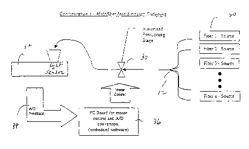
Referring to Fig. 3, in an exemplary embodiment, the feedback servo
control 18 comprises the following components, namely, a light sensor 32 for
detecting
the intensity of the light transmitted by the source fiberoptic cable 12, an
A/D converter
34 for converting the detected intensity into digital electrical signals, and
control circuitry
36 for controlling the motorized positioning stage 14 to adjust the alignment
of the source
and the destination fiberoptic cables 12, 16 in accordance with the digital
electrical
signals.
In a preferred embodiment, the light sensor 32 for detecting the intensity
of the light transmitted by the source fiberoptic cable 12 is a
photomultiplier tube. The
photomultiplier tube is a type of photodetector which detects the presence of
photons by
their intensity and then subsequently amplifies the detected intensity,
thereby facilitating
any needed analyses. Alternative devices which may be used as light sensors to
detect the
intensity of light include CCD's (charge coupled devices), photodiodes, and
other photon
counting devices.
Once the light transmitted by the source fiberoptic cable 12 is detected, the
analog signal captured by the photomultiplier tube is then converted by the
A/D converter
34 into digital electrical signals. Various A/D devices commonly used in the
art to
convert analog light signal into digital electrical signals are available
including, for
example, a device manufactured by Advanced Micro Devices with model number P/N
AD976A.
_7_
CA 02382565 2002-02-20
WO 01/16639 PCT/US00/24247
The digital electrical signals are then used to adjust the alignment of the
source and destination fiberoptic cables 12, 16 to achieve an optimal
transmission
efficiency. In one preferred embodiment, the control circuitry 36 for
interpreting the
digital electrical signals to control the alignment is a controller integrated
circuit
(controller IC) and a software program. The controller IC is programmed by the
software
program to scan an area at a certain acceleration and velocity to detect the
intensity of the
light transmitted. A commercially available product which may be used as the
controller
IC for this purpose is a device manufactured by National Semiconductor with
model
number LM629M. The software program used to control the controller IC may be
implemented as a separate program resident outside of the controller IC or as
firmware
embedded inside the controller IC.
The intensity of the light is detected and scanned in the following basic
manner. Various scanning mechanisms and devices are commonly known in the art
for
detecting and scanning the intensity of light. In one preferred embodiment,
light
transmitted from the source fiberoptic cable 12 is directed to hit a film
having an area of
about ten (10) square millimeters. For scanning purposes, the film is divided
into a grid
of rows and columns. The scanning mechanism is initially calibrated to home in
on an
initial starting scan position, generally located at one of the lower or upper
corners of the
grid. This initial starting scan position is needed to provide a fixed
reference position for
all subsequent measurements to be taken. The scanning then starts from the
initial
starting scan position and examines each column from top to bottom (or vice
versa), i.e.,
row by row, and then sequentially from column to column until all the desired
rows and
columns are scanned. A second or any desired number of subsequent scans may be
performed iteratively to ensure the accuracy of the readings. The maximum
readings are
recorded based on a dual coordinate system by position of the rows and
columns. These
maximum readings represent the location of the detected light on the film.
Using these
readings, the software program then directs the motorized positioning stage 14
to adjust
the position of the source fiberoptic cable 12 relative to the destination
fiberoptic cable 16
to obtain the optimal alignment thus improving the transmission efficiency. In
the
foregoing arrangement, it is assumed that the destination fiberoptic cable 16
is maintained
at a fixed reference position relative to the source fiberoptic cable 12.
Alternatively, the
source fiberoptic cable 12 can be maintained as a reference instead.
To compensate for any loss in efficiency due to subsequent changes, such
as movement in the source or destination fiberoptic cables 12, 16 or other
components,
_g_
CA 02382565 2002-02-20
WO 01/16639 PCT/US00/24247
the scanning process may be re-initiated periodically to verify the location
of the
maximum readings and remedial adjustment may be made by the motorized
positioning
stage 14 accordingly.
There are other ways to perform the column-by-column scan. For
S example, instead of scanning all the columns and rows one by one as
described above, a
divide-and-conquer strategy, similar to a binary search, may be used. Using
this strategy,
only a selected number of columns are initially examined. The coordinates of
the area,
i.e., the delimiting columns and rows, containing the maximum readings are
recorded.
Another selected number of columns and/or rows within this area is then
scanned a
second time to further constrict the area containing the precise location of
the maximum
readings. This process is then iterated until the desired resolution for the
area containing
the maximum readings is reached. In general, as the area is iteratively
constricted, the
selected number of columns and/or rows used for scanning is proportionally
increased to
better identify where the maximum readings appear.
The following is the sequence of events which generally take place when a
preferred embodiment of the present invention is in operation. When the system
10 is
first turned on, the feedback servo control 18 engages a self calibrating mode
identifying
the initial starting scan position. Light from one of the multiple light
sources 20 is then
transmitted via its designated optical fiber 24, 26, 28 within the source
fiberoptic cable 12
to a film for scanning. The intensity of the light as received on the film is
then detected
by the photomultiplier tube and converted by the A/D converter 34 into digital
electrical
signals. The scanning process iterates itself, as previously described above,
to identify
the location of the maximum readings on the film. After having identified the
maximum
readings, the controller IC controlled by the software program then directs
the motorized
positioning stage 14 to make the necessary adjustments to achieve optimal
alignment
between the source and the destination fiberoptic cables 12, 16. The
controller IC under
the control of the software program periodically performs the scanning process
to verify
the location of the maximum readings, and if necessary, directs the motorized
positioning
stage 14 to make any remedial adjustments.
Referring to Fig. 4, an exemplary embodiment of the present invention is
shown incorporated into another device 38. This device 38 can be any device
that
requires light to be transmitted from one or more light sources 20 to a
destination or
application 22. For example, this device 38 can be a scanner. As shown
therein, the
system 10 permits multiple light sources 20 to be selectively transmitted to a
destination
-9-
CA 02382565 2002-02-20
WO 01/16639 PCT/US00/24247
22, in this case, a scan head. In another application, the present invention
can be used to
provide proper alignment for telecommunication connections along
telecommunication
lines spanning extended distances. Each telecommunication connection can be
periodically monitored or adjusted after occurrence of a triggering event,
such as an earth
quake, by the present invention to ensure optimal signal transmission. Based
on the
disclosure provided herein, a person reasonably skilled in the art will know
of other ways
and methods to apply the present invention to other applications.
It is understood that the examples and embodiments described herein are
for illustrative purposes only and that various modifications or changes in
light thereof
will be suggested to persons skilled in the art and are to be included within
the spirit and
purview of this application and scope of the appended claims. All
publications, patents,
and patent applications cited herein are hereby incorporated by reference for
all purposes
in their entirety.
-10-