Note : Les descriptions sont présentées dans la langue officielle dans laquelle elles ont été soumises.
CA 02383618 2002-02-21
WO 01/97609 PCT/USO1/19777
INSECT COLLECTION DEVICE
RELATED APPLICATION
This application claims the benefit of U.S. Provisional Application
Serial No. 60/213,008 filed on June 21, 2000.
FIELD OF THE INVENTION
The present invention generally relates to the field of insect collection
and/or removal. More particularly, the present invention concerns an insect
collection device which may be manually actuated to draw insects into an
interior region for collection or extermination. The present invention also
provides a method for capturing insects.
BACKGROUND OF THE INVENTION
Insects are among the most industrious animals on Earth, capable of
living in almost any land habitat. Nearly one million species of insects are
known to exist, many of which serve industrially beneficial uses in the
ecosystem, while others are capable of destroying crops, trees, and houses
and even carry harmful diseases such as malaria.lnsects also provide a
source of enjoyment or entertainment for some whose hobby is their
collection, and others who keep insects as pets by maintaining ant farms,
beehives and the like. Perhaps for most others, however, insects are
considered pests that bite or sting and appear in unwanted places such as
homes, offices, restaurants, and the like.
Many different types of pest control products are available to alleviate
such nuisances. For example, topical skin creams and sprays help deter
insects from stinging or biting. Similarly, insecticides are used by many in
homes and other indoor areas to help prevent insects from entering.
However, while these types of treatments may temporarily lessen the
nuisance attributed to insects, they are generally ineffective at alleviating
the
problem in its entirety.
When insects enter indoor areas, many are likely to remove or
exterminate them. Depending on the extent of the problem, it may be
necessary to consult a certified exterminator to alleviate the problem.
Perhaps the most common, and simplest way of killing and removing an
CA 02383618 2002-02-21
WO 01/97609 PCT/USO1/19777
2
insect, however, is through the use of a flyswatter or other crude concoction
such as a rolled-up newspaper. Commercially available flyswatters are both
practical and inexpensive and typically have a long handle for reaching
insects that have alighted from high or hard to reach areas. Though simple
and efficient, the drawback to these types of techniques is the unsightly
remnants of the insects which are left behind on walls or windows,
necessitating an additional clean-up step for the individual. Other known
insect extermination techniques include flypaper and "bug lights" which serve
to both attract and kill the flying insect. These types of devices, however,
also have certain drawbacks that make their use indoors impractical because
they are only efficient at killing insects in designated locations and also
require subsequent removal of the exterminated pests.
Vacuum cleaners provide an attractive alternative to the
aforementioned devices and have long been used to assist in the removal or
extermination of insects. Vacuum cleaners typically do not present the
individual with an additional clean-up step and provide a more sanitary and
practical approach to removing insects from indoor areas. Vacuum cleaners
are also more capable in removing insects due to the use of various
attachments that extend the reach of the hose, narrow or widen the extent of
the vacuum area, or provide special shapes that allow easy use for certain
areas. Some attachments have been specifically designed to make the
vacuum cleaner a more efficient tool for removing insects. For example, U.S.
Patent Nos. 4,279,095 to Aasen; 4,630,329 to Shores, and 4,488,331 to
Ward each disclose attachments made for use with vacuum cleaners for the
distinct purpose of capturing and removing insects.
While the collection of insects with a vacuum cleaner does not involve
some of the uncleanly aspects of other conventional approaches, it too is not
without certain disadvantages. For example, the length of an electrical cord
or the length of the hose will limit the reach of many vacuum cleaners. Also,
some vacuum cleaners can be cumbersome and awkward to maneuver,
presenting a precarious situation for an operator requiring the use of a chair
CA 02383618 2002-02-21
WO 01/97609 PCT/USO1/19777
3
or a ladder to reach the insect. Finally, many vacuum cleaners have such a
strong vacuum effect that the insect is killed once it is contained within the
bag or other capturing device, such that these types of devices are not an
attractive alternative for those individuals who want to capture insects for
collection purposes.
There are several types of insect collection devices that have been
designed to remedy some of these drawbacks. For example, U.S. Patent
No. 5,175,960 and related Patent No. 5,402,598, both to Wade, disclose a
collection device designed as a handheld battery operated vacuum.
Although this device is not as cumbersome as some vacuum cleaners, or
limited by the length of an electrical cord, its reliance on batteries to
generate
the necessary vacuum creates a different disadvantage. In addition to
adding a separate expense, batteries have a limited useful life requiring that
be replaced or recharged to properly operate the device. As the battery
begins to expire, it becomes less capable of capturing the insects. Since the
operator may not be aware of the battery's power, the device is less
dependable, and capable of failure at an inopportune time. Another example
is U.S. Patent No. 4,733,495 to Winnicki that discloses a handheld device
wherein the insect is drawn into the device by means of a vacuum. Although
this device is not dependent upon a separate power source, the vacuum is
generated by the movement of a tube from a retracted position to an
extended position. .. This requires the operator to ascertain the appropriate
distance from which to hold the device from the insect to be captured. As a
result, if the device is used incorrectly, the forward thrusting of the tube
can
potentially cause damage to walls, glass, or other surfaces on which the
insect is found.
Accordingly, there remains a need to provide a new design and
construction for an insect removal device that is easy to hold, does not
require the an external power source, and that effectively captures the insect
such that it does not escape. There is a further need to provide a design and
construction for an insect removal device that is portable, easy to use and
CA 02383618 2002-02-21
WO 01/97609 PCT/USO1/19777
4
easy to manufacture and maintain. The present invention is directed to
meeting these needs.
SUMMARY OF THE INVENTION
It is an object of the present invention to provide a new and useful
device for the collection and/or removal of insects
It is another object of the present invention to provide an insect
collection device that uses a vacuum effect created by manual actuation to
draw in and trap insects.
A further object of the present invention is to provide an insect
collection device which is adaptable for use in hard to reach areas, such as
crevices and other small enclosures, while alleviating the cleanup mess
associated with known techniques.
It is yet another object of the present invention to provide an insect
collection device that is lightweight, reusable, easy to use, and provides a
sanitary way of collecting and removing insects for use in indoor areas.
A still further object of the present invention is to provide an insect
collection device with a viewing area to give the operator the ability view
the
captured insects, and to determine when the device needs to be cleaned.
Yet another object of the present invention is to provide an insect
collection device that is easy to clean because it can be disassembled.
It is another object of the present invention to provide an insect
collection device having a mechanism capable of trapping the collected
insect so as to prevent the insect from escaping the collection area.
Yet another object of the present invention is to provide an insect
collection device that is relatively inexpensive and easy to manufacture and
inexpensive to purchased.
In accordance with these objectives, an insect collection device
comprises an elongated and preferably tubular housing having a first end and
extending from the first end in a downstream direction to terminate at a
second end to define a housing interior. A partition separates the housing
interior into a first/upstream region proximate to the first end and a
CA 02383618 2002-02-21
WO 01/97609 PCT/USO1/19777
second/downstream region proximate to the second end. The partition is
constructed to permit air to flow between the first and second regions while
impeding the passage of insects therebetween. A movable closure is
disposed on a first end portion of the housing and moves between a first
(closed) position to hinder access to the upstream region from the first end
and a second (open) position to create an entryway into the upstream region
from the first end. A compression chamber is disposed on a second end
portion of the housing and operates when moved from a compressed position
to an uncompressed position to urge the closure into the open position such
that insects in a vicinity of the first end are drawn into the upstream region
for
collection.
Preferably, the compression chamber is in fluid communication with
the downstream region of the housing and is also operative when moved
from the uncompressed position to the compressed position to eject air from
the housing interior and to create a vacuum within the housing interior when
allowed to move from the compressed position to the uncompressed position.
The insect collection device of the present invention also preferably includes
a triggering assembly that is operative when placed in an engaged state to
retain the compression chamber in the compressed position, and when
moved from the engaged state to a disengaged state, to allow the
compression chamber to return to the uncompressed position. To this end,
the triggering assembly may include a plunger shaft moveable with the
compression chamber between a retracted position when the compression
chamber is in the uncompressed position and an armed position when the
compression chamber is in the compressed position. The triggering
assembly further includes a trigger switch operative to engagedly retain the
plunger shaft in the armed position, thereby to define the engaged state for
the triggering assembly, and to release from the plunger shaft to allow the
compression chamber to move from the compressed position to the
uncompressed position, thereby to define the disengaged state for the
triggering assembly. The plunger shaft preferably has its proximal end
CA 02383618 2002-02-21
WO 01/97609 PCT/USO1/19777
6
connected to a butt end of the compression chamber and extends from the
proximal end into the housing interior to terminate at a distal end. The
trigger
switch is resiliently biased into engagement with a notch when the plunger
shaft is in the armed position. This notch may be formed as a region of
reduced thickness along a medial portion of the plunger shaft. Where a
triggering assembly is provided, the housing is preferably formed to include a
trigger guard which projects on opposite sides of a trigger button that is
coupled to the trigger switch.
In another embodiment of the present invention, the insect collection
device comprises a tubular housing and compression chamber as discussed
above, as well as a collection member releaseably disposed on the housing's
second end. The collection member may include a collection tube adapted to
attach to the first end portion and having an outer surrounding sidewall which
surrounds a collection region. A partition, as discussed above, is disposed
within the collection tube to permit airflow between the collection region and
the housing interior, while impeding the passage of insects therebetween.
The moveable closure is disposed on an upstream end of the collection tube
and moves between an open orientation whereby insects can be drawn into
the collection region and a closed orientation to prohibit insects from
entering
into the collection region.
The moveable closure may be formed by a pair of trap doors.
Alternatively, the moveable closure may include an annular ring which is
sized and adapted to fit over the collection tube, and a plurality of closure
flaps each having an attached portion secured to the webbing and a free
portion to allow the closure flaps to swing about the attached portion as the
compression chamber moves from the compressed position to the
uncompressed position.
It is also preferred that the collection tube have a circumferential
groove formed therein, with the partition formed as a screen mesh seated
against this groove and tapered in the upstream direction toward the central
longitudinally axis of the collection tube. With the exception of the primary
CA 02383618 2002-02-21
WO 01/97609 PCT/USO1/19777
7
housing section which supports the various components of the triggering
assembly, etc., it is also preferred that the remaining upstream tubular
sections of the insect collection device be transparent to allow for viewing
of
insects trapped therein.
In either of the above embodiments, it is preferred that the housing be
selectively extensible to vary an effective length thereof. To this end, the
housing extends along an central longitudinal axis and includes a plurality of
tubular housing sections. that are mateable with one another so that the
effective length of the housing may be varied. Among these tubular housing
sections is preferably a primary housing section that is releaseably attached
to the compression chamber and formed by a pair of primary housing pieces
that are mateable with one another. The compression chamber, which may
be in the form of a flexible bellows, is attached to this primary housing
section
such as by a securement clamp. Where a plurality of tubular housing
sections are provided, the moveable closure is disposed on a terminal,
upstream one of these tubular housing sections.
It is preferred that the compression chamber be resiliently biased into
the uncompressed position and that the moveable closure be biased into the
closed position, yet urged into the open position as the compression chamber
is returned to the uncompressed position from the compressed position. A
purge valve may be associated with the housing and operates as the
compression chamber moves from the uncompressed position to the
compressed position to allow the air to escape from the housing interior.
The present invention also contemplates a method of capturing of
insects. According to this methodology, an elongated retention tube is
provided having a moveable closure at an upstream end portion that is
biased into a closed position. Air is evacuated from the retention tube to
establish a potential vacuum source therein. An upstream end portion of the
retention tube is placed adjacent to a target insect, and air pressure is
created within an interior upstream end portion of the retention tube that is
less than ambient pressure at the upstream end whereby ambient air is
CA 02383618 2002-02-21
WO 01/97609 PCT/USO1/19777
drawn into the retention tube at a sufficient flow to cause the moveable
closure to move into an open position and to draw the insect into the
retention tube.
The method may also include a step of providing a compressible
chamber at a downstream end portion of the retention tube, with the step of
evacuating air from the retention tube being accomplished by compressing
the chamber into a compressed position. Further, the step of creating air
pressure within the upstream end portion of the retention tube that is less
than ambient pressure may be accomplished by returning the compressible
chamber to an uncompressed position. Finally, the step of evacuating air
from the retention tube may be accomplished either before or after its
upstream end portion is placed adjacent to the target insect.
These and other objects of the present invention will become more
readily appreciated and understood from a consideration of the following
detailed description of the exemplary embodiments of the present invention
when taken together with the accompanying drawings, in which:
BRIEF DESCRIPTION OF THE DRAWINGS
Figure 1 (a) is a perspective view of the insect collection device
according to a first exemplary embodiment of the present invention, and
showing the device in the relaxed state;
Figure 1 (b) is a perspective view of the insect collection device of
Figure 1 (a) and showing it in a ready state;
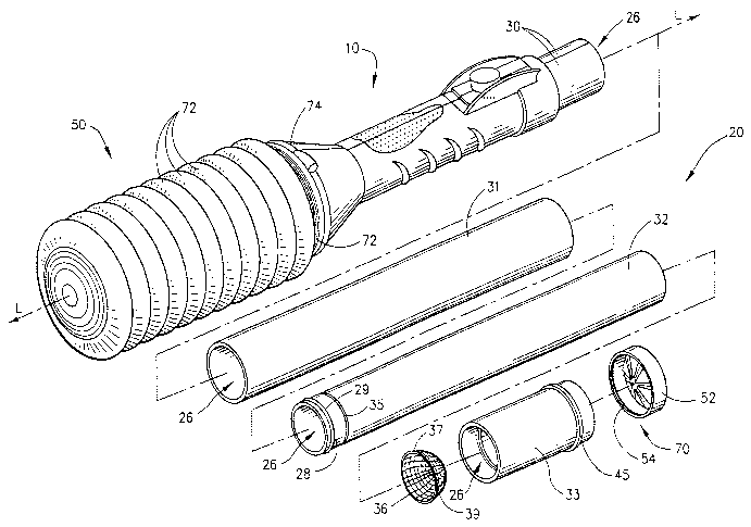
Figure 2 is an exploded perspective view of the insect collection
device of Figures 1 (a) and 1 (b) to show the various tubular housing sections
thereof;
Figure 3(a) is a partial right side view in elevation and in cross-section
of the insect collection device when it is in the relaxed state;
Figure 3(b) is a partial right side view in elevation and in cross-section
view of the insect collection device when it is in the ready state;
Figure 4 is an exploded perspective view of the insect collection
device's primary housing section and its internal triggering assembly;
CA 02383618 2002-02-21
WO 01/97609 PCT/USO1/19777
9
Figures 5(a) and 5(b) are each perspective views of the primary
housing section's left housing piece;
Figures 6(a) and 6(b) are each perspective views of the primary
housing section's right housing piece;
Figure 7 is a side view in elevation and in cross-section of one of the
housing's tubular sections;
Figure 8 is a side view in elevation and in cross-section of another of
the housing's tubular sections;
Figure 9 is a side view in elevation and in cross-section of the
housing's collection tube section;
Figure 10(a) is a side view in cross-section and in elevation of the
housing's tubular sections in an assembled state;
Figure 10(b) is a side view in cross-section and in elevation of two of
the housing's tubular sections shown fully telescoped;
Figures 11 (a) and 11 (b) are cross-sectional views showing an
upstream end portion of the insect collection device when the closure
member is in the closed position and open position, respectively;
Figures 12(a) and 12(b) are perspective views showing the upstream
end portion of the insect collection device when the closure member is in the
closed position and open position, respectively;
Figures 13(a) and 13(b) are upstream end views of the closure
member when it is in the closed position and open position, respectively;
Figure 14 is a right side view in elevation and in cross-section of the
insect collection device's compression chamber;
Figure 15 is an end view in elevation of the insect collection device's
securement clamp;
Figure 16 is a left side view in elevation and in cross-section of the
insect collection device's bellows pad;
Figure 17 is a enlarged perspective view of the insect collection
device's first plunger shaft bearing guide;
CA 02383618 2002-02-21
WO 01/97609 PCT/USO1/19777
Figure 18 is a enlarged perspective view of the insect collection
device's second plunger shaft bearing guide;
Figure 19 is a perspective view of the insect collection device's trigger
switch;
Figure 20 is a side view in elevation of the insect collection device's
purge valve;
Figures 21 (a) and 21 (b) are each perspective views of the insect
collection device's purge valve ring;
Figure 22 is a right side view in elevation of an insect collection device
according to the second exemplary embodiment of the present invention;
Figure 23 is a right side view in elevation and in cross-section
showing an upstream region for the insect collection device of Figure 22;
Figure 24 is a right side view in elevation and in cross-section of one
of the housing's tubular sections;
Figure 25 is a right side view in elevation of another of the housing's
tubular sections;
Figure 26 is a right side view in elevation and in cross-section of the
tubular section of Figure 25;
Figure 27 is an exploded perspective view to illustrate the screen
mount's attachment to the tubular section of Figure 24;
Figure 28 is a perspective view of the left piece which forms a
component part for the primary housing section according to the second
exemplary embodiment;
Figure 29 is a perspective view of the right piece which forms a
component part of the primary housing section for the second exemplary
embodiment;
Figure 30 is an exploded perspective view to illustrate the attachment
of the collection nozzle to tubular section of Figures 25 and 26;
Figure 31 is a somewhat enlarged perspective view of the collection
nozzle's left piece;
CA 02383618 2002-02-21
WO 01/97609 PCT/USO1/19777
~1
Figure 32 is a somewhat enlarged perspective view of the collection
nozzle's right piece;
Figure 33 is an exploded perspective view to illustrate the mounting of
the closure member's trap doors to the collection nozzle;
Figure 34 is a perspective view of a representative one the closure
member's trap door;
Figure 35 is a perspective view of a representative one of the spring
clasps for use in attaching the trap door of Figure 34 in the manner shown in
Figure 33;
Figure 36 is a view in elevation and in cross-section of the screen
mount;
Figure 37 is a right side view in elevation of an insect collection device
according to a third exemplary embodiment of the present invention and
showing portions thereof in phantom; and
Figure 38 is a right side view in elevation and in partial cross-section
showing an insect collection device according to a fourth exemplary
embodiment of the present invention.
DETAILED DESCRIPTION OF THE EXEMPLARY EMBODIMENTS
The present invention, as shown and described with reference to the
exemplary embodiments herein, eliminates the known drawbacks found in
the prior art by providing an insect collection device that is easy to
operate,
requires no external power sources, and provides for easy manufacture and
maintenance. The invention also provides an improved solution for the
collection of live insects, as well as a means for exterminating captured
insects. Referring more particularly to the drawings, a first exemplary
embodiment of the insect collection device 10 of the present invention is
introduced in Figures 1 (a) and 1 (b). Insect collection device 10 is in the
form
of a hand operated mechanism which can be placed in close proximity to a
target insect and manually actuated to draw the target insect into a
collection
region through a suctioning effect. As shown in these figures, insect
collection device 10 comprises an elongated and generally tubular housing
CA 02383618 2002-02-21
WO 01/97609 PCT/USO1/19777
12
20, a moveable closure 50 and a compression chamber 70. Housing 20
extends about a housing interior along a central longitudinal axis "L" from a
first upstream end 22 to terminate in a second downstream end 24.
Moveable closure 50 is disposed on an upstream end portion of housing 20,
while compression chamber 70 is disposed on a downstream end portion of
housing 20. As will be discussed in greater detail below, moveable closure
50 is operative to move between a first (closed) position wherein insects in a
vicinity of the upstream end 22 are prevented from entering into the housing's
interior, to a second (open) position which creates an entryway into the
upstream interior region of housing 20. As compression chamber 70 is
selectively moved between an uncompressed position (Figure 1 (a)) and a
compressed position (Figure 1 (b)), this controls the orientation of moveable
closure 50.
In order to allow collection of insects in hard to reach areas, housing
20 is preferably an extensible member so that an effective length thereof may
be selectively varied. To this end, housing 20 may include a plurality of
plastic tubular sections 30-33 that are matable with one another so that the
effective length of housing 20 may be varied. More particularly, housing 20
in this first exemplary embodiment includes a primary housing section 30,
first and second extension tube sections 31 and 32 and a collection tube 33.
Tubes 31-33 are shown in Figures 7-9, respectively.
With reference to Figure 2, first extension tube section 31 has a
circular cross section and is telescopically received over an upstream end
portion of primary housing section 30 and retained there by frictional
engagement. An upstream end of first extension tube 31 is provided with an
inner circumferential ridge 34 so that when it is telescopically received over
a
downstream end portion of second extension tube 32, as shown in Figure
10(a), and the effective length of tube sections 31 and 32 is increased, as
shown in Figure 10(b), ridge 34 is captured in an outer circumferential groove
35 formed in second extension tube 32 to prevent inadvertent separation
during use. Also provided on second extension tube 32 is a circumferential
CA 02383618 2002-02-21
WO 01/97609 PCT/USO1/19777
13
O-ring seat 28 which receives an O-ring 29 to provide for a sealed
engagement between tube sections 31 and 32. An upstream end portion of
second extension tube 32 may then be telescopically received within
collection tube 33 to form the extensible set of extension sections.
The construction of collection tube 33 may be appreciated with
reference to Figures 2 and 9. Collection tube 33 may also be a tubular
plastic piece having a circular cross-section that is formed to include inner
and outer circumferential ridges 44 and 45, respectively. Disposed within
collection tube 33 is a partition, preferably in the form of a mesh screen 36
which tapers in the upstream direction. Mesh screen 36 is constructed of an
appropriate material, such as an integrally molded plastic piece or stamped
aluminum, and preferably includes an annular ring 37 which is sandwiched
between inner circumferential groove 44 and the upstream end of extension
tube 32 when the device is assembled. Attached to annular ring 37 is a
meshing 39 which is impervious to insects. Mesh screen 36 is sized and
adapted to be press fit into collection tube 36 so that it does not dislodge
once insects are collected and the collection tube is removed.
Moveable closure 50 in the first exemplary embodiment of the insect
collection device 10 of the present invention is formed as an end cap that is
disposed over an upstream end portion of collection tube 33. Moveable
closure 50 is maintained on collection tube 33 by a snap-fit engagement. To
this end, as shown in Figures 11 (a) and 11 (b), moveable closure 50 includes
an annular ring section 49 provided with a lip 54 that is sized and adapted to
engage an annular recess 47 formed in collection tube 33 adjacent to outer
circumferential ridge 45. As such, moveable closure 50 fits snuggly over the
upstream end portion of collection tube 33 to prevent dislodgment during use.
Once the insect collection device 10 is in the assembled state, as shown in
various ones of the figures, mesh screen 36 forms a partition which
separates the housing interior 26 into an upstream insect collection region
25, generally defined within collection tube 33 between mesh screen 36 and
CA 02383618 2002-02-21
WO 01/97609 PCT/USO1/19777
14
moveable closure 50, and a downstream region 27 that is to the left of mesh
screen 36 in the figures.
The remainder of the moveable closure's construction, and its ability to
assume open and closed orientations can now be better appreciated with
reference to Figures 12(a), 12(b), 13(a) and 13(b). Secured to the annular
ring 49 of closure member 50 are a plurality of equiangularly spaced-apart
closure flaps 51. Each of closure flaps 51 is a generally triangular and
wedge-shaped member having two vertices 52 and 53 secured to an inner
surface of annular ring 49 and a free vertex 54. Preferably, movable closure
50 is a one-piece molded plastic construction which has been die cut to form
the closure flaps 51. When the closure flaps 51 are in the closed position
(Figures 12(a) and 13(a)), they resemble a hub and spoke arrangement so
that they essentially close off access to the collection region 25 from its
upstream end. When in the closed orientation, and as perhaps best shown in
Figure 11 (a), bent portions 55 of vertices 54 come together. However, when
the vacuum effect is created by insect collection device 10, such that the
pressure within the collection region 25 and the housing interior 26 is less
than ambient pressure, closure flaps 51 are caused to fan out from one
another as shown in Figures 11 (b), 12(b) and 13(b) into the open position
thereby providing an entryway into the collection region 25 as target insects)
are drawn in. After this happens, and the pressure begins equalize, closure
flaps 51 return to the closed position.
As shown in various one of the figures, compression chamber 70 is
preferably in the form of a flexible bellows having a plurality of hinged ribs
72
joined together in an accordion-like manner so that compression chamber 70
can be moved between the uncompressed position and the compressed
position. Because a vacuum effect is created in order to effectively capture
insects in a vicinity of the housing's upstream end 22, it is preferred to
securely attach compression chamber 70 to the downstream end portion 24
of housing 20. To this end, and as shown in Figure 14, the compression
chamber's bellows structure is provided with an upstream neck 73 which is
CA 02383618 2002-02-21
WO 01/97609 PCT/USO1/19777
sized and adapted to be placed over the second end portion of housing 20.
A securement clamp 74 (Figure 15) is formed as a metallic ring that is sized
to be placed over the compression chamber's neck 73 once the neck is
received over the housing's first end portion. Securement clamp 74 is
provided at one end thereof with a screw 75 which is adapted to threadedly
engage a cooperative socket 76 formed on an opposing circumferential end
of the securement clamp 74, as known in the art. In this manner, the
tendency for the compression chamber 70 to become detached from the
housing 20 upon use of insect collection device 10 is reduced. However, the
ordinarily skilled artisan should readily appreciate that compression chamber
70 could be attached to housing 20 in a variety of different manners other
than that described herein. In any event, though, it is preferred that
compression chamber 70 be capable of securely, yet releaseably, attaching
to the housing 20 so that the insect collection device 10 may be easily
cleaned and reassembled as desired.
Figures 3(a) and 3(b) respectively show insect collection device 10 in
a relaxed configuration wherein compression chamber 70 is in the
uncompressed position, and a ready configuration wherein compression
chamber 70 is in the compressed position. As may also be seen in these
figures, insect collection device 10 includes a triggering assembly 80 which
is
mechanically coupled to compression chamber 70 and is operative when
placed in an engaged state (Figure 3(b)) to retain compression chamber 70
in the compressed position. Triggering assembly 80 is also operative upon
activation by a user to move from the engaged state to a disengaged state
(Figure 3(a)) and thereby allow compression chamber 70 to return to the
uncompressed position. Triggering assembly 80 broadly includes a metallic
plunger shaft 84 that is moveable with compression chamber 70 between a
retracted position when compression chamber 70 in the uncompressed
position, and an armed position when compression chamber 70 is in the
compressed position.
CA 02383618 2002-02-21
WO 01/97609 PCT/USO1/19777
16
Triggering assembly 80 also includes a trigger button 86 and its
associated trigger switch 82 which operates to engagedily retain plunger
shaft 84 in the armed position. Plunger shaft 84 is disposed entirely within
insect collection device 10 and travels longitudinally along its central
longitudinal axis "L". A proximal end 83 of plunger shaft 84 is secured to the
butt end 77 of compression chamber 70 via a fastening screw 42 which
extends through a pair of spaced-apart metallic washers 41 and 43 as well as
a central bore 85 (Figure 14) formed in the downstream end of bellows 70,
such that a portion of the bellows is sandwiched therebetween. A
corresponding bore (not shown) is also formed in the proximal end portion of
plunger shaft 84 so that fastening screw 42 may be threadedly received
therein. A resilient bellows pad 66 is then attached, such as via an acrylic
adhesive, to the recess formed in the downstream end of compression
chamber 70. As shown in Figure 16, bellows pad 66 is provided with
concentric cylindrical cut outs 65 and 67 which are, respectively, sized and
adapted to accommodate the head of fastening screw 42 and washer 41. As
such, bellows pad 66 provides a cushioned contact surface for a user's palm
as he/she manually urges compression chamber 70 in the direction of the
enlarged arrow in Figure 3(b) so that it moves into the compressed position.
Plunger shaft 84 extends from its proximal end within the housing
interior 26 along central longitudinal axis "L" to terminate at a plunger
shaft
distal end. A pair of longitudinally spaced apart plunger shaft bearing guides
60 and 62 are fixedly disposed relative to primary housing section 30 and
serve to both rigidify the internal assemblage and provide guide ways for
plunger shaft 84 as it travels in the longitudinal direction. First plunger
shaft
bearing 60 is shown in Figure 17 as an integral plastic construction which
includes a collar 54 which is concentric with a tubular section 56 and
attached thereto by a plurality of equiangularly spaced apart fins 58. When in
the assembled state, fins 58 are orientated so that they converge toward
longitudinal axis "L" in the downstream direction. Tubular section 56 provides
a first passageway through which plunger shaft 84 is received. When
CA 02383618 2002-02-21
WO 01/97609 PCT/USO1/19777
17
assembled, a first coiled compression spring 6 is seated between washer 43
and a downstream facing surface 57 of first plunger shaft bearing guide 60 in
order to bias compression chamber 70 into the uncompressed state.
Second plunger shaft guide bearing 62 is also fixedly disposed within
primary housing section 30 upstream of trigger switch 82 and, as shown in
Figure 18, also includes an associated collar 61, tubular section 63 and fins
64, such that associated tubular section 63 provides a second passageway
for a corresponding portion of plunger shaft 84. A second compression spring
8 is disposed for compression between an upstream end 69 of second
plunger shaft bearing guide 62 and a metallic washer 81 that is attached to
the upstream end of plunger shaft 84 via an appropriate fastening screw 67.
Second compression spring 8 serves the purpose of preventing the upstream
end of plunger shaft 84 from traveling in the downstream direction beyond
second plunger shaft bearing guide 62 as the plunger shaft moves from the
armed position to the retracted position.
Trigger switch 82 is also disposed within housing interior 26 and
extends transversely to longitudinal axis "L". The construction of trigger
switch 82 is shown in Figure 19 and an integral plastic piece having a central
annular portion 87 provided with a lobe-shaped opening 88 and a pair of
oppositely projecting legs 89 and 90. Lobe-shaped opening 88 has an
enlarged region 88' which is sized and adapted to accommodate the larger
cross-section region of plunger shaft 84, and a reduced region 88" which is
sized and adapted to accommodate a medial portion 85 of plunger shaft 84
that is of reduced thickness. As also shown ~in Figure 19, lower leg 90 of
trigger switch 86 has a tapered end 91 to facilitate movement of the trigger
switch 86 during use.
Having discussed various aspects of the general construction for
insect collection device 10, the assemblage thereof can now be better
appreciated. Conveniently, primary housing section 30 is formed, as shown
in Figures 5(a) - 6(b), by matable pairs of primary housing pieces 28 and 29
to facilitate the assembly process. Each of these pieces 28 and 29 has an
CA 02383618 2002-02-21
WO 01/97609 PCT/USO1/19777
18
outwardly flared downstream portion 31 and 31', respectively, so that when
they are assembled housing section 30 has a generally conical portion sized
and adapted to accommodate the neck 72 of compression chamber 70 and
first bearing guide 60. Once the plunger shaft's proximal end has been
fastened to the butt end of the compression chamber, and the bellows pad
adhered to the compression chamber 70, the remainder of the assemblage
can proceed as follows. Plunger shaft 84 can then be passed through first
compression spring 6 and first plunger shaft bearing guide 60 so that first
compression spring 6 is seated between washer 43 and seat 57. Then, the
plunger shaft 84 is passed through the lobe-like opening 88 of trigger switch
82 as well as second plunger shaft guide bearing 62 and second
compression spring 8. As appreciated with references to Figures 4 through
6(b), primary housing section pieces 28 and 29 are then appropriately
positioned about this internal assemblage so that the collar 54 of first
plunger
shaft bearing guide 60 is aligned with opposed arcuate grooves 44 and 44'
formed in housing pieces 28 and 29, respectively. Similarly, second plunger
shaft bearing guide 62 is appropriately positioned so that its collar 61 is
aligned with opposed arcuate grooves 45 and 45'. A triggering spring 87 is
then placed over lower trigger arm 90 and trigger button 86 is placed over
upper arm 89. This sub-assemblage is then positioned so that lower arm 90
is seated within corresponding cut out sections 46 and 46' formed in housing
piece sections 28 and 29, respectively, while the cap of trigger button 86 is
passed through opposed arcuate cut outs 47 and 4T until the brim of trigger
button 86 is resiliently urged into contact with the inner surfaces of pieces
28
and 29 by virtue of the restorative force of triggering spring 87, A purge
valve
78 (Figure 20) is then passed through its associated purge valve ring 79
(figures 21 (a) and 21 (b) that has a hub and spoke-like construction. The
purge valve ring 79 is then positioned within purge valve seat portions 48 and
48' formed in pieces 28 and 29, respectively.
Once the internal triggering assembly 80 is assembled and positioned,
such as in the manner discussed above, opposed primary housing section
CA 02383618 2002-02-21
WO 01/97609 PCT/USO1/19777
19
pieces 28 and 29 can then be mated with one another by press fitting them
together such that the various alignment holes 12 associated with left
housing piece 28 register with correspondingly positioned nubs 14 formed in
second piece 29. Pieces 28 and 29 may then be securely fastened together
with securement screws 16 which threadedly engage aligned openings 18
and 18' formed in pieces 28 and 29, respectively. The neck 73 of bellows 70
can then be placed over collar sections 48 and 48' associated with first and
second pieces 28 and 29, respectively, and thereafter secured through the
use of the securement clamp 74 as discussed above. As desired, one or
more tubular extensions can then be selectively attached to primary housing
section 30, as well as the assembled collection member 50 as also discussed
hereinabove.
Once assembled, insect collection device 10 is ready for use. In
operation, an individual prepares insect collection device 10 for use by
grasping primary housing section 30 with one of his/her hands. Knurling and
finger recess are provided for added comfort. Using the palm of his/her other
hand, the user then compress bellows 70 against the restorative force of
spring 6 into the compressed position of Figure 1 (b). This causes a
corresponding movement of plunger shaft 84 in the upstream direction until
the notched medial portion 85 of plunger shaft 84 which has a reduced
thickness begins to pass through lobe-like opening 88 of trigger switch 82.
The upward bias on trigger spring 87 then urges lobe-like opening 88 into
contact with medial portion 85 so that medial portion 85 is seated within
lower
lobe portion 88" of trigger 82. During this compression, air escapes through
the purge valve 78 in the direction of arrows "A" in Figure 3(b). This allows
the insect collection device 10 to be placed in the armed state without
pressurizing the interior and without causing moveable closure 50 to be
inadvertently placed in the open position. The user can then relieve pressure
on bellows 70 and the restorative force of spring 6 urges the shoulder of
plunger shaft 84 into engagement with arm 90. At this point, insect collection
CA 02383618 2002-02-21
WO 01/97609 PCT/USO1/19777
device 10 is in a ready state with triggering assembly 80 correspondingly in
an engaged position.
Once the user approaches a target insect whereby the upstream end
22 of housing 20 is positioned in close proximity to the target insect, the
user
depresses trigger button 86, thereby dislodging trigger 82 from medial portion
85. Trigger guards 19 and 19' are provided on housing pieces 28 and 29 to
help prevent inadvertent activation of the device prior to use. The
restorative
force of spring 6 then causes a vacuum effect within the housing interior as
compression chamber 70 returns to the uncompressed state along with the
corresponding movement of plunger shaft 84 to the retracted position. This
vacuum effect urges closure 50 into the open position and, at the same time,
draws the target insect into collection tube 33. As the suctioning effect
reduces and the pressure within housing interior 26 begins to equalize with
the ambient pressure, closure 50 is restored to its closed position, thereby
confining the captured insect within collection tube 33 between screen 36
and closure 50, At this point, if desired, the process can be repeated to
capture additional insects which can be viewed through collection tube 33 by
virtue of its transparency.
A second exemplary embodiment of the insect collection device of the
present invention will now be described with reference to Figures 22 - 36.
Insect collection device 110 is generally introduced in Figure 22 and, as with
insect collection device 10 discussed above, comprises a housing 120, a
moveable closure 150, a compression chamber 170 and a triggering
assembly 180. Insect collection device 110 is constructed similarly to insect
collection device 10 discussed above, with the exception that its upstream
portion is somewhat different. Accordingly, only those portions of insect
collection device 110 which differ from that discussed above with reference to
the first exemplary embodiment will be described.
The upstream portion of insect collection device 110, when in the fully
assembled state, is shown in Figure 23. Housing 120 includes a pair of
tubular and telescopically received housing section 130 and 140. As shown
CA 02383618 2002-02-21
WO 01/97609 PCT/USO1/19777
21
in Figure 24, first tubular housing section 130 is provided with an inner
circumferential ridge 138 at its upstream end. As shown in Figure 25, second
tubular housing section 140 is provided with an outer circumferential groove
142 and an outer circumferential ridge 144 along its downstream end portion
so that when first tubular section 130 is telescopically received over second
tubular section 140 as shown in Figure 23, ridge 144 provides a limit stop for
the extensible set as they are telescopically extended to their full length
wherein it comes into contact with inner circumferential ridge 138. Also as
before, an O-ring 143 is seated within outer circumferential groove 142 to
provide a sealed engagement between the two housing sections. In this
regard, the construction of the upstream portion of insect collection device
110 is similar to that discussed above with reference to the first embodiment.
As shown in Figures 28 and 29, however, the two pieces 121 and 122
of primary housing section 120 have their upstream ends constructed
somewhat differently. Namely, these upstream ends 123 and 124 are
enlarged and, respectively, provided with grooved portions 125 and 126 so
that, a screen mount 160 can be seated therein when insect collection device
110 is in the assembled state. With reference again to Figure 23, screen
mount 160 is formed to include a screen profile which supports a tapered
mesh screen 138 that is impervious to insects as there are drawn into
collection region 125. The construction of the various pieces for the screen
mounting sub-assembly may be best appreciated with reference to Figures
27 and 36. Screen mount 160 has a generally cylindrical main body provided
with a generally circuitous brim 162 which is sized and adapted to engage
grooved portions 125 and 126, respectively, of housing pieces 121 and 122
when in a mounted state so that screen mount 160 is fixedly positioned within
an interior of insect collection device 110. A plurality of converging support
posts 164 project from an opposing end of the main body of screen mount
160 to form the screen mount. Posts 164 supportably position a prong
element 166. It should be noted that screen mount 160 is preferably
constructed as a unitary piece of plastic material. A pre-formed, tapered
CA 02383618 2002-02-21
WO 01/97609 PCT/USO1/19777
22
mesh screen 138 having an aperture (not shown) is then sized and adapted
to be placed over prong element 166 so that it drapes over these support
posts 164. Screen 138 is held in this position by a notched clip mount 141.
A downstream end portion of tubular section 130 is attached to screen
mount 160 via snap fit engagement prior to being clamped between primary
housing pieces 121 and 122. More particularly, tubular section 130 is formed
to include a pair of opposed arcuate cut outs 136 so that when a user grasps
screen mount 160, finger tabs 161 thereof may be aligned with cut outs 136
to allow screen mount 160 to be inserted into tubular section 130.
Thereafter, the user can then grasp cross piece 163 and press fit screen
mount 160 into engagement with tubular section 130 whereby protrusions
165 snap into engagement with corresponding notches 134 formed on an
inner surface of tubular section 130. With reference again to Figure 23,
screen mount 160 can be easily ejected from tubular section 130 by driving
inner telescoping tubular section 140 in the downstream direction to separate
the engagement of protrusions 165 from notches 134.
A bayonet connection is employed to fixedly mount moveable closure
150 to nozzle section 180. As shown in Figure 30, second tubular section
140 is also provided with a pair of opposed protrusions 146 which are
alignable with channels 182 associated with nozzle 180, whereby the tubular
portion of nozzle 180 can be inserted within second tubular section 140 and
rotated so that protrusions 146 become locked into notches 184 associated
with nozzle 180. A compressible ring 170 may also be placed over nozzle
180 so that it is seated within collar 186 to provide a sealed engagement
between nozzle 180 and an inner sidewall surface 145 of second tubular
section 140 when they are mated.
Nozzle 180 is formed by a pair of matable pieces 181 (Figure 31 ) and
191 (Figure 32) which mount moveable closure 150. Reference will now be
made to Figures 31-35 to describe the mounting assembly for moveable
closure 150. Moveable closure 150 includes a pair of trap doors 152 and 154
which are mounted between nozzle pieces 181 and 191. A representative
CA 02383618 2002-02-21
WO 01/97609 PCT/USO1/19777
23
one of these doors 152 is shown in Figure 34 to include an arcuate door
panel 153 and a door hinge 155 having protruding ends. It should be
appreciated, of course, that second door 191 has an identical construction.
Each of doors 152 and 154, when in the mounted state, are resiliently biased
into a closed position through the provision of an associated clip spring,
such
as clip spring 172 shown in Figure 35. More particularly, and with reference
to door 152, its associated spring 172 is placed such that its looped portion
173 is disposed about one leg of hinge 155. These are then aligned with a
shaft hole 183 formed in first nozzle piece 181 so that when door 152 is
mounted as shown in Figure 33, an upper leg 174 of spring clip 172 rests
against face panel 153, while a lower leg 176 of spring clip 172 rests against
an inner surface of nozzle piece 181. Wall sections 185 and 195 are formed
as part of nozzle pieces 181 and 191 to prevent first door 152 from swinging
open outwardly beyond the opened position. Second door 154 is mounted
between nozzle pieces 181 and 191 in a like manner. As such, it can be
appreciated that doors 152 and 154 are resiliently biased into their closed
position, yet permitted to swing into an open position upon creation of the
vacuum effect discussed above with reference to the first exemplary
embodiment for the insect collection device 10 of the present invention.
Target insects are then drawn into collection region 125 where they are
maintained between partition screen 138 and the trap doors. As may also be
seen in various ones of the figures for this second exemplary embodiment for
the insect collection device 110, nozzle 180 has internal threads 186 and 196
formed on its nozzle pieces 181 and 191. This allows a user, if desired, to
threadedly attach a correspondingly threaded vessel within which the
captured insects) are drawn and then trapped by replacing nozzle 180 with
an appropriate closure cap.
A third exemplary embodiment of an insect collection device according
to the present invention is shown in Figure 37. As before, the discussion of
insect collection device 210 will be confined to those portions which differ
from embodiments discussed hereinabove. In insect collection device 210,
CA 02383618 2002-02-21
WO 01/97609 PCT/USO1/19777
24
that portion of primary housing section 220 which is upstream of trigger guard
219 has simply a tubular construction 222 which is telescopically received
within first tubular section 230. Figure 37 also shows second tubular section
240 telescopically received within first tubular section 230, as discussed
above. Here, however, a collection vessel 270 has its neck 272 threadedly
attached to the tubular portion 286 of nozzle 280. Vessei 270 has an open
bottom and an inserted mesh screen 238 as described with reference to the
first embodiment. The interior of vessel 270, thus, provides the confined
collection region for the insects, thereby eliminating the need for the screen
mount assembly discussed above with reference to the second exemplary
embodiment.
In Figure 38, a fourth exemplary embodiment of the insect collection
device of the present invention is shown. Here, insect collection device 310
has its primary housing section 320 joined to tubular section 330 by a coupler
324 which surrounds an upstream end portion of primary housing section 320
and a downstream end portion of tubular section 330. Necessarily, then,
coupler 324 has opposed openings within which primary housing section 320
and tubular section 330 may be inserted in a close-fitting, mated
engagement. In a similar manner, an upstream end collar 380 telescopically
receives an upstream end portion of 330 and mounts the trap doors of
moveable closure 350 in a manner such as that discussed above with
reference to the second exemplary embodiment. Also shown in this fourth
exemplary embodiment is a mesh screen 338 which is formed by integrally
molding tubular section 330 so that it is provided with a tapering basket
weave section from which extends a prong 340 which supports a wick 370
that can be coated in any appropriate manner with insecticide to exterminate
captured insects.
Having discussed the various exemplary embodiments for the
construction of the insect collection device of the present invention, it
should
be readily appreciated that the present invention also contemplates a method
of capturing insects. According to this method, an elongated retention tube is
CA 02383618 2002-02-21
WO 01/97609 PCT/USO1/19777
provided having a moveable closure at an upstream end portion that is
biased into a closed position. Air is then evacuated from the retention tube
to
establish a potential vacuum source therein. An upstream end portion of the
retention tube is then placed adjacent to a target insect, and air is created
within an interior upstream end portion of the tube that is less than ambient
pressure at the upstream end, whereby ambient air is drawn into the
retention tube at a sufficient flow to cause the moveable closure to move into
an open position and to draw the insect into the retention tube.
The methodology may also incorporate the step of providing a
compressible chamber at a downstream end portion of the retention tube,
with the compression chamber being biased into an uncompressed position.
The step of evacuating air from the retention tube is accomplished by
compressing the chamber into a compressed position, where it may be
mechanically maintained. Further, the step of creating air pressure within the
upstream end portion of the retention tube that is less than ambient pressure
is accomplished by returning the compressible chamber to the
uncompressed position.
Accordingly, the present invention has been described with some
degree of particularity directed to the exemplary embodiments of the present
invention. It should be appreciated, though, that the present invention is
defined by the following claims construed in light of the prior art so that
modifications or changes may be made to the exemplary embodiment of the
present invention without departing from the inventive concepts contained
herein.