Note : Les descriptions sont présentées dans la langue officielle dans laquelle elles ont été soumises.
CA 02384582 2002-05-02
17GE07112
HIGH TEMPERATURE SUPER-CONDUCTING ROTOR COIL SUPPORT WITH
SPLIT COIL HOUSING AND ASSEMBLY METHOD
BACKGROUND OF THE INVENTION
The present invention relates generally to a super-conductive coil in a
synchronous
rotating machine. More particularly, the present invention relates to a coil
support
structure for super-conducting field windings in the rotor of a synchronous
machine.
Synchronous electrical machines having field coil windings include, but are
not
limited to, rotary generators, rotary motors, and linear motors. These
machines
generally comprise a stator and rotor that are electromagnetically coupled.
The rotor
may include a multi-pole rotor core and one or more coil windings mounted on
the
rotor core. The rotor cores may include a magnetically-permeable solid
material, such
as an iron-core rotor.
Conventional copper windings are commonly used in the rotors of synchronous
electrical machines. However, the electrical resistance of copper windings
(although
low by conventional measures) is sufficient to contribute to substantial
heating of the
rotor and to diminish the power efficiency of the machine. Recently, super-
conducting (SC) coil windings have been developed for rotors. SC windings have
effectively no resistance and are highly advantageous rotor coil windings.
Iron-core rotors saturate at an air-gap magnetic field strength of about 2
Tesla.
Known super-conductive rotors employ air-core designs, with no iron in the
rotor, to
achieve air-gap magnetic fields of 3 Tesla or higher. These high air-gap
magnetic
fields yield increased power densities of the electrical machine, and result
in
significant reduction in weight and size of the machine. Air-core super-
conductive
rotors require large amounts of super-conducting wire. The large amounts of SC
wire
add to the number of coils required, the complexity of the coil supports, and
the cost
of the SC coil windings and rotor.
1
CA 02384582 2002-05-02
17GE07112
High temperature SC coil field windings are formed of super-conducting
materials
that are brittle, and must be cooled to a temperature at or below a critical
temperature,
e.g., 27 K, to achieve and maintain super-conductivity. The SC windings may be
formed of a high temperature super-conducting material, such as a BSCCO
(Bi,,Sr,,Ca,,Cu,,O,,) based conductor.
Super-conducting coils have been cooled by liquid helium. After passing
through the
windings of the rotor, the hot, used helium is returned as room-temperature
gaseous
helium. Using liquid helium for cryogenic cooling requires continuous
reliquefaction
of the returned, room-temperature gaseous helium, and such reliquefaction
poses
significant reliability problems and requires significant auxiliary power.
Prior SC coil cooling techniques include cooling an epoxy-impregnated SC coil
through a solid conduction path from a cryocooler. Alternatively, cooling
tubes in the
rotor may convey a liquid and/or gaseous cryogen to a SC coil winding that is
immersed in the flow of the liquid and/or gaseous cryogen. However, immersion
cooling requires the entire field winding and rotor structure to be at
cryogenic
temperature. As a result, no iron can be used in the rotor magnetic circuit
because of
the brittle nature of iron at cryogenic temperatures.
What is needed is a super-conducting field winding assemblage for an
electrical
machine that does not have the disadvantages of the air-core and liquid-cooled
super-
conducting field winding assemblages of, for example, known super-conductive
rotors.
In addition, high temperature super-conducting (HTS) coils are sensitive to
degradation from high bending and tensile strains. These coils must undergo
substantial centrifugal forces that stress and strain the coil windings.
Normal
operation of electrical machines involves thousands of start-up and shut-down
cycles
over the course of several years that result in low cycle fatigue loading of
the rotor.
Furthermore, the HTS rotor winding should be capable of withstanding 25% over-
speed operation during rotor balancing procedures at ambient temperature, and
2
CA 02384582 2002-05-02
17GE07112
notwithstanding occasional over-speed conditions at cryogenic temperatures
during
power generation operation. These over-speed conditions substantially increase
the
centrifugal force loading on the; windings over normal operating conditions.
SC coils used as the HTS rotor field winding of an electrical machine are
subjected to
stresses and strains during cool-down and normal operation. They are subjected
to
centrifugal loading, torque transmission, and transient fault conditions. To
withstand
the forces, stresses, strains and cyclical loading, the SC coils should be
properly
supported in the rotor by a coil support system. These coil support systems
hold the
SC coil(s) in the HTS rotor and secure the coils against the tremendous
centrifugal
forces due to the rotation of the rotor. Moreover, the coil support system
protects the
SC coils, and ensures that the coils do not prematurely crack, fatigue or
otherwise
break.
Developing support systems for HTS coils has been a difficult challenge in
adapting
SC coils to HTS rotors. Examples of coil support systems for HTS rotors that
have
previously been proposed are disclosed in U.S. Patents Nos. 5,548,168;
5,532,663;
5,672,921; 5,777,420; 6,169,353, and 6,066,906. However, these coil support
systems suffer various problenis, such as being expensive, complex and
requiring an
excessive number of components. There is a long-felt need for a HTS rotor
having a
coil support system for a SC coil. The need also exists for a coil support
system made
with low cost and easy-to-fabricate components.
BRIEF SUMMARY OF THE 1NVENTION
A coil support system has been developed for a racetrack shaped, high
temperature
super-conducting (HTS) coil winding for a two-pole rotor of an electrical
machine.
The coil support system prevents damage to the coil winding during rotor
operation,
supports the coil winding with respect to centrifugal and other forces, and
provides a
protective shield for the coil winding. The coil support system holds the coil
winding
with respect to the rotor. The HTS coil winding and coil support system are at
cryogenic temperature while the rotor is at ambient temperature.
3
CA 02384582 2002-05-02
17GE07112
The split-housing coil support is particularly useful for a low power density
High
Temperature Super-conducting (HTS) electric machine. The coil support
withstands
the high centrifugal and tangential forces that would otherwise act on the SC
coil.
The coil housings are positioned end-to-end along the long side sections of
the coil
winding in order to evenly distribute the centrifugal and tangential forces
that act on
the coil. To reduce the heat leakage, the mass of the coil support has been
minimized
to reduce thermal conduction from the rotor through support into the cold
coil. The
coil support is maintained at cryogenic temperatures, as is the field winding.
The coil support system includes a series of coil support assemblies that span
between
opposite sides of the racetrack coil winding. Each coil support assembly
includes a
tension rod and a pair of split coil housings. The tension rods extend between
opposite sides of the coil winding through conduits, e.g., holes, in the rotor
core. A
split coil housing at each end of the tension rod attaches to the coil. The
housing
transfers centrifugal forces from the coil to the tension rod. Each coil
support
assembly braces the coil winding with respect to the rotor core. The series of
coil
support assemblies provides a solid and protective support for the coil
winding.
Each split coil housing comprises a pair of opposite side panels that are
assembled
around the SC coil and grasps an end of the tension rod. The side panels are
"C"
shape pieces which are fastened together by bolts to enclose the coil between
a pair of
side panels. Clamping bolts hold the side panels together and prevent the coil
housing
from splitting under large centrifugal and tangential loads.
The HTS rotor may be for a synchronous machine originally designed to include
SC
coils. Alternatively, the HTS rotor may replace a copper coil rotor in an
existing
electrical machine, such as in a conventional generator. The rotor and its SC
coils are
described here in the context of a generator, but the HTS coil rotor is also
suitable for
use in other synchronous machines.
The coil support system is useful in integrating the coil support system with
the coil
and rotor. In addition, the coil support system facilitates easy pre-assembly
of the coil
4
CA 02384582 2002-05-02
17GE07112
support system, coil and rotor core prior to final rotor assembly. Pre-
assembly
reduces coil and rotor assembly time, improves coil support quality, and
reduces coil
assembly variations.
In a first embodiment, the invention is a rotor for a synchronous machine
comprising:
a rotor core; a super-conducting coil winding extending around at least a
portion of
the rotor core, the coil winding having a side section adjacent a side of the
rotor core;
at least one tension rod extending through a conduit in the rotor core; and a
housing
attached to the tension rod and connected to the side section of the coil
winding,
wherein the housing comprises a pair of side panels.
In another embodiment, the invention is a method for supporting a super-
conducting
coil winding in the rotor core of a synchronous machine comprising the steps
of:
extending a tension rod through a conduit in the rotor core; positioning the
coil
winding around the rotor core such that the tension rod and tension bolt span
between
side sections of the coil winding; assembling a pair of side panels of at
least one
housing around a side section of the coil winding; securing side panels
together, and
attaching the housing to a first end of the tension rod.
BRIEF DESCRIPTION OF THE DRAVJINGS
The accompanying drawings in conjunction with the text of this specification
describe
an embodiment of the invention.
FIGURE 1 is a schematic side elevational view of a synchronous electrical
machine
having a super-conductive rotor and a stator.
FIGURE 2 is a perspective view of an exemplary racetrack super-conducting coil
winding.
FIGURE 3 is a partially cut-away view of the rotor core, coil winding and coil
support
system for a high temperature super-conducting (HTS) rotor.
CA 02384582 2002-05-02
17GE07112
FIGURES 4 and 5 are perspective views of a split coil housing having a coil
(Fig. 5)
and without a coil (Fig. 4).
FIGURE 6 is a perspective view of the rotor core, coil winding and coil
support
system for a high temperature super-conducting (HTS) rotor.
DETAILED DESCRIPTION OF THE INVENTION
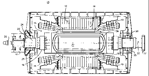
FIGURE 1 shows an exemplary synchronous generator machine 10 having a stator
12
and a rotor 14. The rotor includes field winding coils that fit inside the
cylindrical
rotor vacuum cavity 16 of the stator. The rotor fits inside the rotor vacuum
cavity of
the stator. As the rotor turns within the stator, a magnetic field 18
(illustrated by
dotted lines) generated by the rotor and rotor coils moves/rotates through the
stator
and creates an electrical current in the windings of the stator coils 19. This
current is
output by the generator as electrical power.
The rotor 14 has a generally longitudinally-extending axis 20 and a generally
solid
rotor core 22. The solid core 22 has high magnetic permeability, and is
usually made
of a ferromagnetic material, such as iron. In a low power density super-
conducting
machine, the iron core of the rotor is used to reduce the magnetomotive force
(MMF).
The reduced MMF minimizes the amount of super-conducting (SC) coil wire needed
for the coil winding. For example, the solid iron-rotor core may be
magnetically
saturated at an air-gap magnetic field strength of about 2 Tesla.
The rotor 14 supports at least one longitudinally-extending, racetrack-shaped,
high-
temperature super-conducting (HTS) coil winding 34 (See Fig. 2). The HTS coil
winding may be alternatively a saddle-shape or have some other shape that is
suitable
for a particular HTS rotor design. A coil support system is disclosed here for
a
racetrack SC coil winding. The coil support system may be adapted for coil
configurations other than a racetrack coil mounted on a solid rotor core.
The rotor includes a pair of end shafts that bracket the rotor core 22. A
collector end
shaft 24 has collector rings 78 that provide an external electrical coupling
for the SC
6
CA 02384582 2002-05-02
17GE07112
coil. The collector end shaft also includes a cryogen transfer coupling 26 to
a source
of cryogenic cooling fluid used to cool the SC coil windings in the rotor. The
cryogen
transfer coupling 26 includes a stationary segment coupled to a source of
cryogen
cooling fluid and a rotating segment which provides cooling fluid to the HTS
coil.
The opposite end shaft is a drive shaft 30 that may be connected to a power
turbine.
The end shafts are supported by bearings 25 that provide supports for the
entire rotor.
FIGURE 2 shows an exemplary HTS racetrack field coil winding 34. The SC field
winding coils 34 of the rotor includes a high temperature super-conducting
(SC) coil
36. Each SC coil includes a high temperature super-conducting conductor, such
as a
BSCCO (Bi,,Sr,,CaCu,,OX) conductor wires laminated in a solid epoxy
impregnated
winding composite. For example, a series of BSCCO 2223 wires may be laminated,
bonded together and wound into a solid epoxy impregnated coil.
SC wire is brittle and easy to be damaged. The SC coil is typically layer
wound SC
tape that is epoxy impregnated. The SC tape is wrapped in a precision coil
form to
attain close dimensional tolerances. The tape is wound around in a helix to
form the
racetrack SC coil 36.
The dimensions of the racetrack coil are dependent on the dimensions of the
rotor
core. Generally, each racetrack SC coil encircles the magnetic poles of the
rotor core,
and is parallel to the rotor axis. The coil windings are continuous around the
racetrack. The SC coils form a resistance-free electrical current path around
the rotor
core and between the magnetic poles of the core. The coil has electrical
contacts 79
that electrically connect the coil to the collector 78.
Fluid passages 38 for cryogenic cooling fluid are included in the coil winding
34.
These passages may extend around an outside edge of the SC coil 36. The
passageways provide cryogenic cooling fluid to the coil and remove heat from
the
coil. The cooling fluid maintains the low temperatures, e.g., 27 K, in the SC
coil
winding needed to promote super-conducting conditions, including the absence
of
electrical resistance in the coil. The cooling passages have an input fluid
port 39 and
7
CA 02384582 2002-05-02
17GE07112
output fluid port 41 at one end of the rotor core. These fluid (gas) ports 39,
41
connect the cooling passages 38 on the SC coil to tubes in the rotor end shaft
24 that
extend to the cryogen transfer coupling 26.
Each HTS racetrack coil winding 34 has a pair of generally-straight side
portions 40
parallel to a rotor axis 20, and a pair of end portions 54 that are
perpendicular to the
rotor axis. The side portions of the coil are subjected to the greatest
centrifugal
stresses. Accordingly, the side portions are supported by a coil support
system that
counteract the centrifugal forces that act on the coil.
FIGURE 3 shows a partially cut-away view of a rotor core 22 and coil support
system
for a high temperature super-conducting (HTS) coil winding. The coil support
systems includes a series of coil support assemblies spanning through the
rotor core
and between opposite sides of the HTS coil winding. Each coil support assembly
comprises a tension rod 42 that extends through a conduit 46 of the rotor
core, and a
split coil housing 44 that is fastened to the rod and brackets the coil
winding. The coil
support system provides a structural frame to hold the coil winding in the
rotor.
The principal loading of the HTS coil winding 34 is from centrifugal
acceleration
during rotor rotation. The coil support assemblies are each aligned with the
centrifugal loading of the coil to provide effective structural support to the
coil
winding under load. To support the side sections of the coil, each tension rod
42
attaches to the split coil housings 44. The housings grasp opposite side
sections of the
coil. The tension rods 42 extend through a series of conduits 46 in the rotor
core.
These rods are aligned with the quadrature axis of the rotor core.
The split coil housings 44 support the coil winding 34 against centrifugal
forces and
tangential torque forces. Centrifugal forces arise due to the rotation of the
rotor.
Tangential forces may arise from acceleration and deceleration of the rotor,
and
torque transmission. Because the long sides 40 of the coil winding are encased
by the
split coil housings 44 and the flat ends 86 of the tension bolts, the sides of
the coil
winding are fully supported within the rotor.
8
CA 02384582 2002-05-02
17GE07112
The conduits 46 are generally cylindrical passages in the rotor core having a
straight
axis. The diameter of the conduits is substantially constant. However, the
ends 88 of
the conduits may expand to a larger diameter to accommodate an insulating tube
52.
This tube aligns the rod 42 in the conduit and provides thermal isolation
between the
rotor core and the rod.
At the end of each tension rod, the insulating tube 52 fastens the coil
support structure
to the hot rotor and prevents heat convection therebetween. Additionally,
there is a
lock-nut 84 connected to the insulating tube 52, that further secures the
connection
with the tension rod. The lock-nut 84 and the tube 52 secure the tension rod
and split
housing to the rotor core while minimizing the heat transfer from the hot
rotor to the
housing structure.
The insulator tube 52 is forrned of a thermal insulation material. One end of
the tube
may include an external ring (not shown) that abuts the wall of the wide end
88 of the
conduit. The other end of the tube includes an internal ring (not shown) that
engages
the lock-nut 84 holding the tension rod to the insulating tube. Heat from the
rotor
would have to conduct through the length of the insulator tube 52 and the lock-
nut 84
before reaching the tension rod. Thus, the insulator tube thermally isolates
the tension
rod from the rotor core.
The number of conduits 46 and their location on the rotor core depends on the
location of the HTS coils and the number of coil housings needed to support
the side
sections of the coils. The axes of the conduits 46 are generally in a plane
defmed by
the racetrack coil. In addition, the axes of the conduits are perpendicular to
the side
sections of the coil. Moreover, the conduits are orthogonal to and intersect
the rotor
axis, in the embodiment shown here. The number of conduits and the location of
the
conduits will depend on the location of the HTS coils and the number of coil
housings
needed to support the side sections of the coils.
There are generally two categories of support for super-conducting winding:
(i)
"warm" supports and (ii) "cold" supports. In a warm support, the supporting
9
CA 02384582 2002-05-02
17GE07112
structures are thermally isolated from the cooled SC windings. With warm coil
supports, most of the mechanical load of a super-conducting (SC) coil is
supported by
structural members that span between the cold coils and the warm support
members.
In a cold coil support system, the support system is at or near the cold
cryogenic
temperature of the SC coils. In cold supports, most of the mechanical load of
a SC
coil is supported by the coil support structural members which are at or near
cryogenic temperature.
The exemplary coil support system disclosed here is a cold support in that the
tension
rods 42, bolts 43 and associated split housings 44 are maintained at or near a
cryogenic temperature. Because the coil support members are cold, these
members
are thermally isolated, e.g., by the non-contact conduits through the rotor
core, from
the rotor core and other "hot" components of the rotor.
The HTS coil winding and structural coil support components are all at
cryogenic
temperature. In contrast, the rotor core is at an ambient "hot" temperature.
The coil
supports are potential sources of thermal conduction that would allow heat to
reach
the HTS coils from the rotor core. The rotor core becomes hot during
operation. As
the coil windings are to be held in super-cooled conditions, heat conduction
into the
coils from core is to be avoided.
The coil support system is thermally isolated from the rotor core. For
example, the
tension rods and bolts are not in direct contact with the rotor. This lack of
contact
avoids the conduction of heat from the rotor to the tension rods and coils. In
addition,
the mass of the coil support system structure has been minimized to reduce the
thermal conduction through the support assemblies into the coil windings from
the
rotor core.
Each tension rod 42 is a shaft with continuity along the longitudinal
direction of the
rod and in the plane of the racetrack coil. The tension rod is typically made
of high
strength non-magnetic alloys such as aluminum or an Inconel alloy. The
longitudinal
continuity of the tension rods provides lateral stiffness to the coils which
provides
CA 02384582 2002-05-02
17GE07112
rotor dynamics benefits. Moreover, the lateral stiffness of the tension rods
42 permits
integrating the coil support with the coils so that the coil can be assembled
with the
coil support on the rotor core prior to final rotor assembly.
The flat surface 86 head of the tension rod supports an inside surface of a
side of the
coil winding. The end 86 of the tension rod may be serrated so that it may be
engaged
into the annular ridges 134 of an assembly of two coil housing side panels 124
(see
Fig. 5). The other three surfaces of the side 40 of the coil winding are
supported by
the split housing 44. Each split housing is assembled around the coil and
forms a coil
casing in cooperation with the bolt head. This casing supports the coil
winding with
respect to tangential and centrifugal loads. The casing also allows the coil
winding to
expand and contract longitudinally.
FIGURES 4 and 5 (and Fig. 3) show one-half of exemplary "C" shaped side panels
124 of the split housing 44. A pair of side panels brackets opposite sides of
a coil 34.
Moreover, side panels are arranged end-to-end along each side of a coil to
form a
continuous coil support assembly along a side section 40 of a coil winding 34.
An
inside surface of each side panel has a narrow slot 130 to receive the wedge
and an
"L" shaped channel 132 to receive a side of the coil. A side surface and an
inner
surface of the coil rests on orthogonal surfaces of the channel 132 of the
side panel.
An opposite side panel is assembled around the coil and supports the same
inner coil
surface and an opposite coil side surface.
The outside surface of the coil is supported by a wedge 126 that extends
between the
side panels on opposite sides of the coil. An individual wedge may be split
(as shown
in Figures 4 and 5) and extend half-way across the coil where it abuts with
another
split wedge. The wedge 126 fits into the narrow slot 130 of a side panel. The
wedge
includes a channel 127 to receive the cooling passage 38 on the outside
surface of the
coil. Further the wedge may include a series of holes 131 that are aligned
with holes
133 at the top edge of the side panel. Each pair of these holes 131, 133
receive
locking pins 136 (Fig. 3) that extend through the opposite side panels and
wedges to
clamp the top edges of the side panels and wedges together.
11
CA 02384582 2002-05-02
17GE07112
The wedge may be integral to the side panel and extend one-half the width of
the coil,
as shown in FIGURE 4. Alternatively, the wedge may be a separate component
that
is assembled with the side panel and may extend one half or the entire
distance across
the width of the coil to an opposite side panel. In addition, the wedge 126
need not be
coextensive with the side panel. The wedge may extend beyond the length of a
side
panel and engage a slot 130 in an adjacent side panel (as shown in Fig. 4).
Alternatively, the wedge may be coextensive with the side panel, as is shown
in
FIGURE 5.
The side panels 124 have a lower flange 135 on which rests the inside surface
of the
coil. Bolt holes 142 in the lower flange allow for clamping bolts to hold
together the
lower portion of the housing 44. The lower flange also engages the tension rod
42 or
tension bolt 43 (depending on whether a solid tension rod is used or a tension
rod and
bolt assembly is being used).
Each side panel (one-half is shown in Figs. 4 and 5) has a half section 134 of
a hole to
engage a tension rod or tension bolt. The side panels shown in FIGURES 4 and 5
have a half section 134 that forms a hole (when assembled with two pair of
side
panels) to engage a serrated end of the tension rod 42 (Fig. 5) or the head of
a tension
bolt 43 (Fig. 4). The hole formed by the side panel shown in FIGURE 4 has a
smooth
bore and an annular ledge 137 to engage the head of bolt 43. Alternatively,
the hole
formed by half section 134 of the side panel shown in FIGURE 5 is serrated and
engages the serrated end of a tension rod. Accordingly, the split housing 44
may be
used with either a tension rod and bolt assembly, or a tension rod without a
bolt.
Further, a lock-nut 138 (see Fig. 6) may be inserted into the threaded hole
134 and the
lock-nut may have an interior hole and ledge to securely hold a tension bolt
head 43.
Regardless of the manner in which the tension bolt or tension rod is attached
to the
lower flange 135 of the side panel, the end of the bolt or rod is secured so
as to abut
the inside surface of the coil. In this way the end of the tension bolt or rod
directly
supports the coil.
12
CA 02384582 2002-05-02
17GE07112
The split housing may be made of light, high strength material that is ductile
at
cryogenic temperatures. Typical materials for the split housings are aluminum,
titanium, and Inconel alloys. The shape of the split housing has been
optimized for
low weight.
As shown in FIGURE 6, a series of split coil housings 44 (and associated
tension
bolts 43 and rods 42) may be positioned along the sides 40 of the coil
winding. The
tension bolts 43 screw into threaded holes (not shown) in the end of the
tension rod.
The depth to which the bolt screws into the rod is adjustable. The total
length of the
tension rod and bolt assembly (which assembly spans between the sides of the
coil)
can be changed by turning one or both of the bolts into or out of the holes of
the
tension rods. The head of the bolt or the end of the tension rod includes a
flange with
a flat outer surface 86. The flange engages the rim of the split housing shown
in
FIGURE 4. The flat head 86 of the bolt or rod abuts an inside surface of the
coil
winding 34.
The housings are arranged end-to-end along the length of the side portion 40
of the
coil. The split housings collectively distribute the forces that act on the
coil, e.g.,
centrifugal forces, over substantially the entire side sections 40 of the
coil. The split
housings 44 prevent the coil side sections 40 from excessive flexing and
bending due
to centrifugal forces.
The plurality of split housings 44 effectively hold the coil in place without
affectation
by centrifugal forces. Although the split housings are shown as having a close
proximity to one another, the housings need only be as close as necessary to
prevent
degradation of the coil caused by high bending and tensile strains during
centrifugal
loading, torque transmission, and transient fault conditions.
The coil supports do not restrict the coils from longitudinal thermal
expansion and
contraction that occur during normal start/stop operation of the gas turbine.
In
particular, thermal expansion is primarily directed along the length of the
side
13
CA 02384582 2002-05-02
17GE07112
sections. Thus, the side sections of the coil slide slightly longitudinally
with respect
to the split housing and tension rods.
The coil support system of tension rods 42, bolts 43 and split housings 44 may
be
assembled with the HTS coil windings 34 as they are mounted on the rotor core
22.
The tension rods and split housings provide a fairly rigid structure for
supporting the
coil winding and holding the long sides of the coil winding in place with
respect to the
rotor core. The ends of the coil may be supported by split clamps (not shown)
at the
axial ends of (but not in contact with) the rotor core 22.
The rotor core and end shafts may be discrete components that are assembled
together. The iron rotor core 22 has a generally cylindrical shape 50 suitable
for
rotation within the rotor cavity 16 of the stator 12. To receive the coil
winding, the
rotor core has recessed surfaces 48, such as flat or triangular regions or
slots. These
surfaces 48 are formed in the curved surface 50 of the cylindrical core and
extending
longitudinally across the rotor core. The coil winding 34 is mounted on the
rotor
adjacent the recessed areas 48. The coils generally extend longitudinally
along an
outer surface of the recessed area and around the ends of the rotor core. The
recessed
surfaces 48 of the rotor core receive the coil winding. The shape of the
recessed area
conforms to the coil winding. For example, if the coil winding has a saddle-
shape or
some other shape, the recess(es) in the rotor core would be configured to
receive the
shape of the winding.
The recessed surfaces 48 receive the coil winding such that the outer surface
of the
coil winding extends to substantially an envelope defined by the rotation of
the rotor.
The outer curved surfaces 50 of the rotor core when rotated define a
cylindrical
envelope. This rotation envelope of the rotor has substantially the same
diameter as
the vacuum rotor cavity 16 (see Fig. 1) in the stator.
The gap between the rotor envelope and stator cavity 16 is a relatively-small
clearance, as required for forced flow ventilation cooling of the stator only,
since the
rotor requires no ventilation cooling. It is desirable to minimize the
clearance
14
CA 02384582 2002-05-02
17GE07112
between the rotor and stator to increase the electromagnetic coupling between
the
rotor coil windings and the stator windings. Moreover, the rotor coil winding
is
preferably positioned such that it extends to the envelope formed by the rotor
and,
thus, is separated from the stator by only the clearance gap between the rotor
and
stator.
The rotor core, coil windings and coil support assemblies are pre-assembled.
Pre-
assembly of the coil and coil support reduces production cycle, improves coil
support
quality, and reduces coil assembly variations. Before the rotor core is
assembled with
the rotor end shafts and other components of the rotor, the tension rods 42
are inserted
into each of the conduits 46 that extend through the rotor core. The insulator
tube 52
at each end of each tension rod is placed in the expanded end 88 at each end
of the
conduits 46. The tube 52 is locked in place by a retainer locking-nut 84. The
bolts
43, if used, may be inserted before or after the tension rods are inserted
into the rotor
core conduits.
When using tension bolts, then a locking nut 138 is placed on each bolt and
then used
to secure the bolt against the split housing. The depth to which the bolts are
screwed
into the tension rods is selected such that the length from the end of one
bolt on a
tension rod to the end of the opposite bolt is the distance between the long
sides 40 of
the coil winding. When the tension rods and bolts are assembled in the rotor
core 22,
the coil windings 34 are ready to be inserted onto the core.
The coil winding 34 is inserted onto the rotor core such that the flat ends 86
of the
tension rods 42 or bolts 43 abut the inside surface of the side sections 40 of
the
winding. Once the winding has been inserted over the ends of the rod 42 or
bolt 43,
the split housings 44 are assembled over the winding. To assemble each
housing, the
side panels are placed against opposite sides of the coil, and the wedges are
slid into
the narrow slots 130 of the side panels. The lock pin is inserted to hold the
wedges
and the side panels together. The lock-nut 138 is used to tighten the side
panels
against the bolt.
CA 02384582 2002-05-02
17GE07112
The rotor core may be encased in a metallic cylindrical shield 90 (shown by
dotted
lines) that protects the super-conducting coil winding 34 from eddy currents
and other
electrical currents that surround the rotor and provides a vacuum envelope to
maintain
a hard vacuum around the cryogenic components of the rotor. The cylindrical
shield
90 may be formed of a highly-conductive material, such as a copper alloy or
aluminum.
The SC coil winding 34 is maintained in a vacuum. The vacuum may be formed by
the shield 90 which may include a stainless steel cylindrical layer that forms
a vacuum
vessel around the coil and rotor core.
The coil split housings, tension rods and bolts (coil support assembly) may be
assembled with the coil winding before the rotor core and coils are assembled
with the
collar and other components of the rotor. Accordingly, the rotor core, coil
winding
and coil support system can be assembled as a unit before assembly of the
other
components of the rotor and of the synchronous machine.
While the invention has been described in connection with what is presently
considered to be the most practical and preferred embodiment, it is to be
understood
that the invention is not to be limited to the disclosed embodiment, but on
the
contrary, is intended to cover all embodiments within the spirit of the
appended
claims.
16