Note : Les descriptions sont présentées dans la langue officielle dans laquelle elles ont été soumises.
CA 02386276 2004-05-10
CAPACITIVE DISCHARGE IGNITION
SYSTEM WITH EXTENDED DURATION SPARK
BACKGROUND OF THE INVENTION
[0002] It is an object of an aspect of the present invention, to provide a
capacitive
discharge ignition system capable of generating an arc discharge between the
spark plug
electrodes with a duration three to six times longer than typical for the type
of ignition coil in
use.
[0003] It is a further object of an aspect of the present invention, to be
able to
adjustably and selectively modify or disable the extended duration spark to
obtain the best
possible spark plug life.
[0004] When engine operation conditions require spark durations previously
unavailable from capacitive discharge ignitions, the extended spark can be
enabled. This
allows the use of a capacitive spark ignition system where inductive-type
ignition systems
were the only practical choice.
SUMMARY OF THE INVENTION
[0005] Briefly, according to the present invention, there is provided a
capacitive
discharge (CD) ignition system for an internal combustion engine. The ignition
system
comprises a storage capacitor and diode in series therewith, a converter
transformer having
primary and secondary windings, the secondary winding thereof connected in
series with the
storage capacitor and diode, an ignition transformer having primary and
secondary windings,
a first triggerable switch, the primary winding of the ignition transformer
and the storage
capacitor being connected in series through the first triggerable switch, a
spark plug
connected in series with the secondary winding of the ignition transformer, a
source of direct
current, and a second triggerable switch connected in series with the primary
of the converter
transformer. A control circuit is provided to control the first and second
triggerable switches
and operates in synchronism with the engine such that while the first switch
is open, the
second switch is closed for a period to store energy in the converter
transformer and then
opened to transfer energy fo the storage capacitor followed by again closing
of the second
switch. The first switch is closed to discharge the storage capacitor to the
primary of the
ignition coil. The second switch is reopened to transfer energy stored in the
converter
transformer to the primary of the ignition transformer to prolong the current
in the secondary
of the ignition transformer. The number of times N the second switch is
reopened and closed
and the time period T for which the
CA 02386276 2002-05-13
second switch remains closed is controlled to control the duration and
amplitude of the
extended arc current.
BRIEF DESCRIPTION OF THE DRAWINGS
[0006] Further features and other objects and advantages will become clear
from the
following detailed description made with reference to the drawings in which:
[0007] Fig. 1 is a schematic of the circuit configuration according to the
present invention;
[0008] Fig. 2 shows standard capacitive discharge circuit waveforms at 4 kV
breakdown
voltage providing a 500 microsecond spark;
[0009] Fig. 3 shows standard capacitive discharge circuit waveforms at 19 kV
breakdown
voltage providing a 380 microsecond spark;
[0010] Fig. 4 shows extended capacitive discharge circuit waveforms, according
to the
present invention, at 5 kV breakdown voltage providing a 1,920 microsecond
spark;
[0011] Fig. 5 shows extended capacitive discharge circuit waveforms, according
to the
present invention, at 19 kV breakdown voltage providing a 1,920 microsecond
spark;
[0012] Fig. 6 shows extended capacitive discharge circuit waveforms, according
to the
present invention, with eight extension pulses;
[0013] Fig. 7 shows extended capacitive discharge circuit waveforms, according
to the
present invention, with twelve extension pulses;
[0014] Fig. 8 shows extended capacitive discharge circuit waveforms, according
to the
present invention, with short duration extension pulses and with low arc
current; and
[0015] Fig. 9 shows extended capacitive discharge circuit waveforms, according
to the
present invention, with long duration extension pulses and with higher arc
current.
DESCRIPTION OF THE PREFERRED EMBODIMENTS
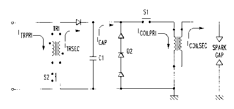
[0016] Referring now to Fig. 1, a transformer TR1 has a primary winding and a
secondary
winding. The primary winding of the first transformer TR1 is connected to a
source of DC
voltage, e.g., a battery, via a switch S2. A storage capacitor C1 is
positioned in parallel with
the secondary winding of transformer TR1. A diode Dl is positioned between the
secondary
winding of the transformer TR1 and the storage capacitor C 1. The diode D 1 is
oriented to
block charging of capacitor C 1 with charging current -ITRSEC from the
secondary winding
when the switch S2 is closed and primary current IT~RI flows from the battery
through the
primary winding of the transformer TR1. A plurality of series connected diodes
D2 is
connected in parallel with storage capacitor C1. The diodes D2 are oriented to
block a
current Icy from storage capacitor C 1 from flowing therethrough. Connected in
parallel with
diodes D2 is a primary side of an ignition coil. Connected between the primary
side of the
-2-
CA 02386276 2002-05-13
ignition coil and the diodes D2 is a switch S 1. The ignition coil has a
secondary side
connected to a spark gap, preferably the gap of a spark plug.
[0017] When switch Sl opens, i.e., prior to an ignition event, the switch S2
is closed and
primary current IT~~ is allowed to flow into the primary winding of the
transformer TR1.
The phasing of the windings of the transformer TRl is selected so that diode
Dl blocks
secondary current -I~EC from flowing through the secondary winding of the
first
transformer TRI. When sufficient energy is stored in the primary of the first
transformer
TR1, switch S2 is opened and energy from the collapsing magnetic field across
the secondary
winding of the first transformer TRl causes secondary current I~EC to flow
through diode
D 1 and charge storage capacitor C 1.
[0018] When it is time to provide a spark, switch S 1 is closed and the
voltage across
storage capacitor C1 is impressed across the primary side of the ignition
coil. After a delay
due to coil inductance, current Ic,~ begins to flow through the primary side
of the ignition
coil. The voltage impressed across the primary side of the ignition coil
causes a voltage to
develop on the secondary side of the ignition coil proportional to the turns
ratio of the
ignition coil. When the secondary voltage increases to a value sufficient to
cause a spark
discharge across the spark gap, coil secondary current IcoILSEC begins to
flow. While the
ignition coil secondary current is flowing, the switch S2 is closed and
current IT~RI flows
through the primary of the first transformer TRI. The ignition coil secondary
current IcoiLSEc
decreases with decreasing current Ic,4,p from storage capacitor C 1.
[0019] At an appropriate time before the secondary current has decreased
sufficiently to
extinguish the spark discharge across the spark gap, the switch S2 is opened
and transformer
TR1 secondary current IT~EC is developed which flows through the ignition coil
primary.
Hence, at this time, the current through the ignition coil primary IconxRC 1S
the sum of the
transformer TR1 secondary current I~rRSEC and the current IcAP from the
storage capacitor C1.
The addition at the appropriate time of the secondary current I~EC from the
secondary coil
of the transformer TRl enables the duration of the spark discharge across the
spark gap to be
extended. Moreover, the inductance of the secondary coil of the transformer
TRl is
connected in series with the inductance of the primary coil of the ignition
coil. Hence, the
inductance of the circuit supplying the current IcoILPRi in the primary side
of the ignition coil
increases with the addition of current IT~EC from the secondary winding of the
first
transformer TRl. This increase in inductance in combination with the secondary
current
ITRSEC provided by the transformer TR1 increases the arc duration in excess of
the sum of the
capacitor current IcAp or the secondary current IT~EC of the transformer TRl
alone.
-3-
CA 02386276 2002-05-13
[0020] The switch S2 can be opened and closed a number of times N to prolong
the spark
current as shown in F igs. 4-9.
[0021] Fig. 2 illustrates the operation of the circuit according to the prior
art. Assume the
capacitor C 1 has been charged, switches S 1 and S2 are both open (non-
conducting). In
response to a trigger pulse, switch S 1 is closed (conducting). This results
in a rush of current
from the capacitor C1 to the primary of the ignition transformer. The spike in
voltage across
the primary of about 180 volts is illustrated by the middle trace of Fig. 2.
This is reflected in
the voltage spike to cause breakdown in the spark gap illustrated in the top
trace of Fig. 2.
The breakdown voltage in the coil secondary in this instance is approximately
4 kV. The
spark duration is approximately 500 microseconds. The bottom trace illustrates
the control
signal applied to the switch S2 to close the switch to permit recharging of
capacitor C1. It
should be understood that switch S 1 had previously been opened.
[0022] Fig. 3 is similar to Fig. 2 except for a different spark gap condition,
wherein the
breakdown voltage across the secondary of the ignition coil is approximately
19 kV. This
results in a spark of reduced duration of 380 microseconds. Hence, according
to the prior art,
the spark duration is related to the breakdown voltage which is a
characteristic of the spark
gap condition.
[0023] Fig. 4 illustrates the operation of a circuit according to the present
invention. After
the initial closing of switch S 1 and following breakdown in the spark gap,
the switch S2 is
repeatedly opened and closed as illustrated in the bottom trace of Fig. 4. In
this instance, the
switch is opened and closed twelve (12) times over a period of 1,520
microseconds. This
causes the primary of the ignition coil to be reenergized as many times and
the duration of the
spark to be extended to 1,920 microseconds.
[0024] Fig. 5 illustrates the operation of a circuit according to the present
invention much
the same as Fig. 4. However, the spark gap conditions were adjusted to
increase the
breakdown voltage in the primary of the ignition coil to 19 kV. The duration
of the spark,
however, remains the same at 1,920 microseconds. Unlike the circuit operating
according to
the prior art procedures, the spark duration is not tied to the spark gap
conditions.
[0025] Fig. 6 illustrates that the spark duration can be controlled by
controlling the number
of reenergizing pulses supplied to the capacitor C 1. In this case, the switch
S2 is closed and
opened eight (8) times over a period of 1,040 microseconds and the spark
duration was
extended to 1,440 microseconds.
[0026] Fig. 7 illustrates the voltage across capacitor C 1 during operation
according to the
present invention, wherein after breakdown, the switch S2 is closed and opened
twelve (12)
-4-
CA 02386276 2002-05-13
times over 1,440 microseconds. Note that the charge on the capacitor C1 is
approximately
170 volts prior to close of the switch S 1. With each opening and closing, the
capacitor is
recharged to about 30 volts.
[0027] Figs. 8 and 9 illustrate the current in the ignition secondary (middle
trace) as
recorded. The difference between the conditions during which Figs. 8 and 9
were recorded is
the width of the time the switch S2 was closed prior to reopening during the
recharging
period. The middle trace reflects ignition coil secondary current. Due to a
serious baseline
drift, the trace requires some interpretation. In theory, the current never
goes negative. In the
test illustrated in both Figs. 8 and 9, twelve equally spaced reenergizing
pulses are used to
extend the spark duration. The pulses permitting current to flow in the
primary of the
converter transformer are wider for the test illustrated in Fig. 9 than in
Fig. 8. The current
peaks with the narrower energizing pulses are about 8 milliamps whereas with
the wider
energizing pulse, the current peaks are at about 40 milliamps.
(0028] Figs. 4 and 5 illustrate that with applicant's invention, the spark
duration is not
dependent on the conditions of the spark gap. Figs. 6 and 7 illustrate that
the duration of the
spark may be controlled by controlling the number of reenergizing pulses.
Figs. 8 and 9
illustrate that the current during the extended spark duration can be
controlled by controlling
the width of the reenergizing pulses.
[0029] Having thus described my invention in the detail and particularity
required by the
Patent Laws, what is desired protected by Letters Patent is set forth in the
following claims.
-5-