Note : Les descriptions sont présentées dans la langue officielle dans laquelle elles ont été soumises.
CA 02386801 2002-04-05
WO 02/24101 PCT/CA01/01301
_1_
Orthodontic Brackets and Convertible Buccal Tubes
Technical Field of the Invention
This invention is concerned with improvements in or relating to
orthodontic devices consisting of orthodontic brackets, particularly
orthodontic
brackets which comprise arch wire attitude controlling spring means as a
permanent part thereof, and buccal tubes of convertible type, which may also
comprise arch wire attitude controlling spring means as a permanent part
thereof.
Background Art
1o Orthodontic procedures almost always employ a plurality of orthodontic
brackets that are attached to respective teeth, increasingly by cementing them
to the teeth, although in some circumstances the bracket still may be attached
to a metal band which embraces the tooth. Each bracket has a mesial distal
extending slot therein, usually of rectangular cross section in a gingival
CA 02386801 2002-04-05
WO 02/24101 PCT/CA01/01301
-2-
occlusal plane, and the brackets are connected together using an arch wire,
so called because it is preformed to an optimum arch shape corresponding to
the desired conformation of the teeth at the conclusion of the procedure.
Arch wires of progressively increasing stiffness and, depending on the type of
tooth movement to be achieved, also of different cross sections, are used one
at a time, the wire being retained in the slots by ligating means of some
kind.
Initially the brackets themselves were "passive", in that ligation of the wire
to
the bracket to obtain the necessary action between them was external to, the
bracket, at first consisting of a soft metal wire twisted around the bracket,
while later an elastomeric hoop or loop increasingly was commonly used in
place of the wire. In another line of development each bracket was made to
be "active" in that it comprised a permanent ligating spring member. Specific
examples of such active brackets are disclosed and claimed in my U.S.
Patents Nos. 3,772,787; 4,248,588; 4,492,573; 4,698,017; 5,685,7117
5,711,666 and 5,906,486, the disclosures of which are incorporated herein
by this reference. Brackets of this type currently are used in the Hanson
SPEED System (Trade Mark) and have proven to be very successful.
The ends of the arch wire may be engaged in so-called buccal tubes,
s
usually attached to the molars on respective sides of the patient's mouth so
as to anchor the arch wire firmly in place, and buccal tubes may also be
employed on intermediate teeth in place of brackets whenever this is
appropriate. In its simplest form a buccal tube is passive and consists of a
short piece of tube attached to a base by which .it is mounted on the tooth
surface, the tube bore opening at' least mesiaily so that the arch wire end
must be inserted therein by moving it distally, This is not always convenient,
and may not be possible when the buccal tube is on an intermediate tooth,
and the solution is then to use a buccal tube of the so-called convertible
type,
with which one side of the tube bore can be opened when required for
insertion of the wire therein or its removal. It is also possible to
incorporate in
3o the tube a wire engaging attitude controlling spring member that will urge
the
wire into contact with two of the slot wails, whereupon the tube is active as
CA 02386801 2002-04-05
WO 02/24101 PCT/CA01/01301
-3-
well as convertible.
It will be apparent from the foregoing brief general description of
brackets and buccal tubes that there can be considerable overlap between
both their function and appearance, with the result that it may be possible
for
a particular orthodontic device to be considered by some orthodontists as a
bracket, while others will think of it as a buccal tube. In general, a device
in
which its body is noticeably bigger in gingival-occlusal dimension than
mesially-distally will usually be regarded by most practitioners as a bracket,
while one in which the opposite is the case will be regarded as a buccal tube.
Inherently buccal tubes, especially those of the passive type, are
smaller than most brackets and can have a smooth exterior. There is a
constant endeavor to provide brackets that are as small and as smooth
exteriorly as possible, for cosmetic reasons to please the patient, in order
to
reduce as much as possible any rough contact between the tongue, the
brackets and the adjacent mouth tissue, with consequent discomfort, and for
hygienic reasons to reduce the number of areas in which food and dental
plaque can accumulate. The orthodontist is interested in addition to use both
brackets and buccal tubes that while low in cost provide fast, precise and
effective movement and attitude control of the teeth.
There is also increasing interest in the so-called lingual technique, in
which the brackets are mounted on the lingual tooth surfaces, so that they
and the arch wire are concealed from frontal view. Lingual procedures are
more difficult to implement and a compromise is to use a lingual technique
only for the upper arch, where the brackets and arch wire would otherwise be
most visible, and a labial technique for the lower arch, where the brackets
and
arch wire are mostly hidden by the lower lip. Lingual and mixed lingualllabial
procedures are of special interest to adult patients who are more concerned
than children with appearance during the two to three year period required for
a typical procedure. Small smooth brackets are needed particularly for the
lingual location because of ready access by the tongue, and the natural
tendency for the tongue to explore any foreign object in the mouth. Attempts
CA 02386801 2002-04-05
WO 02/24101 PCT/CA01/01301
-4-
simply to reduce the size of existing brackets are not generally successful,
at
least partly because changes in scale affects size parameters in different
ratios, e.g. areas decrease in square ratio while volumes decrease in cube
ratio, with the result that it becomes increasingly difficult, especially with
the
tiny spring members required, to find materials of the necessary properties.
Examples of such small smooth exterior brackets suitable for lingual
procedures are those described and claimed in my U.S. Patents Nos.
4,698,017 and 5,685,71 1, issued respectively 06 October 1987 and 11
November 1997, referred to above.
1 o Orthodontics is now a well established branch of dentistry, and the
manufacture of orthodontic equipment is a mature industry. The ongoing
requirement to provide appliances that are efficient, economical and easy to
use increasingly has the added requirement to be as inexpensive as possible,
especially if orthodontists are to be persuaded to make the changes in the
procedures in which they were trained, and with which they are very familiar,
that the adoption of new devices usually entails.
Disclosure of the Invention
It is a principal object of the invention therefore to provide new
orthodontic brackets, which preferably are of the type comprising a permanent
attitude controlling metal spring that can engage an arch wire in the arch
wire
receiving slot, and buccal tubes of the so-called convertible type, which may
also comprise a permanent attitude controlling metal spring .
It. is another principal object to provide new brackets of small size and
of an exterior shape that makes them specially suitable for use in lingual
techniques, particularly in association with incisor or canine teeth.
It is a further object to provide such new brackets and convertible
buccal tubes requiring a minimum number of parts and in which the cost of
their fabrication is minimized.
In accordance with the invention there is provided an orthodontic device
comprising.-
CA 02386801 2002-04-05
WO 02/24101 PCT/CA01/01301
-5-
a device body having labial, lingual, gingival, occlusal, mesial and distal
surface portions, the body having therein a mesial-distal extending arch wire
receiving slot having one side open to a device body surface portion to permit
insertion of an arch wire into the slot, and
a slot closure member mounted by the device body so as to be movable
about a pivot axis between a slot open position in which the open slot side is
open, and a slot closed position in which the closure member closes the open
slot side to retain an orthodontic arch wire in the slot;
wherein the slot closure member comprises:
a pivot portion mounted by the device body for the pivoting movement
of the slot closure member about the pivot axis; and
a slot closure portion movable with the pivot portion and extending
mesially distally with respect to the device body;
and wherein the slot closure portion comprises:
a slot closure part that in the slot closed position closes the open side
of the arch wire slot; and
at least one mesially-distally extending body engaging part that in the
slot closed position of the slot closure member engages with an immediately
adjacent surface portion of the device body with an interference fit butting
engagement between them such that the slot closure member is retained
thereby in the slot closed position, and such that movement of the slot
closure
member into the slot closed position requires flexing of the body engaging
part
in a direction away from the device body against the resilience of the
material
of the body engaging part.
Devices of the invention may constitute an orthodontic bracket ora
convertible buccal tube.
Preferably there is provided in a recess within the device body a flat
attitude controlling spring member having a fixed end portion fixed to the
device body and a free end portion extending into the arch wire receiving slot
for engagement in a mesially-distally extending plane with an arch wire in the
slot, such engagement urging the arch wire toward the slot closure part.
CA 02386801 2002-04-05
WO 02/24101 PCT/CA01/01301
Further in accordance with the invention there is provided an
orthodontic bracket for application to the lingual surface of an incisor or
canine tooth, which teeth are characterized in that their labial-lingual
dimension increases progressively from the gingival to the occlusal, the
bracket comprising:
a bracket body having I'abial, lingual, gingival, occlusal, mesial and distal
surface portions, having therein a mesial-distal extending arch wire receiving
slot with its lingual side open to the lingual surface portion to permit
insertion
of an arch wire into the slot, and having therein a recess opening to the
lingual and occlusal surface portions;
the bracket body also comprising a slot closure member mounted by the
bracket body in the recess so as to be movable about a pivot axis between a
slot open position in which the open slot side is open, and a slot closed
position in which it closes the open slot side to retain an orthodontic arch
wire
therein, the slot closure member also having labial, lingual, gingival,
occlusal,
mesial and distal surface portions;
wherein in the slot closed position the occlusal surface portion of the
slot closure member is flush with the occlusal surface portion of the bracket
body to thereby provide a combined occlusal surface which is unobstructed;
and
wherein the gingival-occlusal dimension of the bracket body decreases
progressively from the lingual to the labial, the decrease corresponding to
the
average increase from the occlusal to the gingival of an incisor or canine
tooth, so that when the bracket is attached to the lingual surface of an
incisor
or canine tooth the unobstructed combined occlusal surface provides a mesiai-
distal, labial-lingual extending bite plane surface which the tooth edge at
the
junction of the occlusal and labial surface portions of an opposed incisor or
canine tooth can engage during biting action to oppose overbite.
Description of The Drawings
Particular preferred embodiments of the invention will now be
CA 02386801 2002-04-05
WO 02/24101 PCT/CA01/01301
described, by way of example with reference to the accompanying
diagrammatic drawings wherein:-
Figure 1 is a perspective view from the mesial-occlusal of a first
embodiment with the pivoting slot closure member in slot closed position;
Figure 2 is a similar perspective view with the slot closure member in
slot open position;
Figure 3 is an exploded view from the same perspective as Figures 1
and 2 of the first embodiment;
Figure 4 is a view in elevation from the lingual of the bracket of Figures
1-3 with the slot closure member in slot closed position, showing in cross
section the operative end of a flat-ended tool used to move the slot closure
member to slot open position;
Figure 5 is a cross section in a lingual-labial, gingival-occlusal plane
through the bracket with the slot closure member in slot closed position, and
with an arch wire of round cross section retained in the slot;
Figure 6 is a view in elevation from the occlusal of the first
embodiment, as it is shown in Figure 5, and with a round arch wire retained in
the slot;
Figure 7 is a cross section similar to Figure 5 with the slot closure
member in slot open position and without an arch wire in the slot;
Figure 8 is a view in elevation from the mesial or distal of an attitude
controlling spring pre-formed ready for incorporation into a bracket;
Figure 9 is a plan view of the spring of Figure 8;
Figures 10 and 11 are cross sections similar to Figure 5 showing a
bracket in use with arch wires respectively of rectangular and quarter round
cross section;
Figure 12 is a cross section similar to Figure 5 of another embodiment
showing an alternative method of retaining an attitude controlling spring in
the
bracket body;
Figure 13 is a view in elevation from the mesial of opposed upper and
lower incisors with a bracket as illustrated by Figures 1-12 cemented to the
CA 02386801 2002-04-05
WO 02/24101 PCT/CA01/01301
_g_
lingual surface of the upper tooth and a conventional Hanson SPEED bracket
cemented to the labial surface of the lower tooth, the teeth being in a
position
corresponding to a typical deep-bite malocclusion prior to the commencement
of ari orthodontic correction procedure;
Figure 14 is a view similar to Figure 13 showing the position of the
teeth at the conclusion of a successful procedure;
Figure 15 is a cross section in a mesial-distal, labial-lingual plane
through a further embodiment showing an alternative structure of a hinge pin
for the slot closure member;
1o Figure 16 is a view in elevation from the labial of a further embodiment
showing the application of the invention to a bracket structure of the so-
called
Siamese twin type;
Figure 17 is a gingival-occlusal longitudinal cross section taken on the
line 17-17 in Figure 16;
Figure 18 is a longitudinal cross section similar to Figure 17 of a
Siamese twin type bracket incorporating an attitude controlling spring that is
a
further embodiment of the invention;
Figure 19 is an elevation similar to Figure 17 of a, further embodiment;
Figure 20 is a perspective view from the distal-occlusal of a further
embodiment comprising a convertible buccal tube with its slot opening to the
occlusal;
Figure 21 is a view in elevation from the distal of the buccal tube of
Figure 20 with its slot closure member in slot closed position;
Figure 22 is a view similar to Figure 21 with the slot closure member in
slot open position;
Figure 23 is view similar to Figure 21 of a buccal tube with its slot
opening to the labial;
Figure24 is a view from the labial of the buccal tube of Figure 23;
Figure 25 is a view similar to Figure 23 showing the inclusion of an
3o attitude controlling spring within the tube to render it active;
Figure 26 is a view in elevation from the mesia( showing the bucca(
CA 02386801 2002-04-05
WO 02/24101 PCT/CA01/01301
-9-
tube of Figures 23 and 24 mounted on the labial surface of an upper first
molar tooth, and showing an alternative structure for the attachment of
elastic
members thereto;
Figure 27 is a labial-lingual, occlusal-gingival cross section through an
active convertible buccal tube in which an attitude controlling spring also
assists in retaining the slot closure member in slot closed position;
Figure 28 is a cross section similar to figure 27 of an active convertible
buccal tube provided with separate attitude controlling and closure member
retaining springs; and
Figure 29 is a cross section similar to figure 27 of a passive convertible
buccal tube provided with a closure member retaining spring.
Description of The Preferred Embodiments
In this specification and the appended claims, for convenience in
language the brackets, buccal tubes and parts thereof are referred to, unless
otherwise specified, as they would be used mounted in the upper arch region
of a patient's mouth, especially in the case of brackets, since those
described.
are intended primarily for use in lingual procedures. However, both the
brackets and the buccal tubes may be used for either labial or lingual
procedures. As applied to the bracket structure the labial and lingual
direction
2o designations are reversed between the two procedures, e.g. the bracket
surface referred to as the labial surface in the labial procedure becomes the
lingual surface in the lingual procedure, and vice versa, and the arch wire
slot
opens to the lingual and not the labial. Again for convenience in description
the brackets are described as having specific named surfaces but, as will be
apparent, smooth exterior contours can only be achieved by avoiding sharp
edges and sharp edged junctions wherever possible, and the various surfaces
therefore usually merge smoothly with one another without a definite junction
between them being apparent.
Similar parts are given the same reference number in all the Figures of
the drawings wherever this is appropriate.
CA 02386801 2002-04-05
WO 02/24101 PCT/CA01/01301
-10-
The brackets of the inverition as described and shown herein are
intended for use with the so-called straight wire technique with which each
bracket is attached to its respective tooth in an attitude such that, as the
arch
wire attempts to return to its preformed arch shape and to be straight as seen
in a mesial-distal, labial-lingual plane, the tooth is moved toward its
desired
optimized position and attitude. In order for the arch wire to be straight at
the
conclusion of the procedure the brackets for different teeth must
accommodate the very different inclinations of the tooth surfaces to which
they are attached. There are two main methods by which this is done, either
1 o by suitable shaping of the bracket bases and of their base surfaces that
contact the teeth surfaces; or by changing the inclination of the arch wire
slots. !n the brackets shown herein all of the torque requirements (rotation
about a mesial distal axis), angulation requirements (rotation about a labial-
lingual axis), and first order pre-adjustments, are obtained by suitable
shaping
of the bracket bases, particularly of the surface that engages the tooth
surface, and by variation of the base thickness, so that when the teeth are in
their optimum attitude and rotational position all of the slot surfaces
engaged
by the arch wire are aligned. The other method of slot inclination can also be
used in the brackets of the invention, either alone or in combiriation with
the
2o first-described method. However, when the other method is used, with some
brackets the inclination of the slot may be so extreme that, for example, in a
bracket fixed to the lingual surface of a central incisor no attempt is made
to
have the slot remain parallel with the labial lingual axis and instead it
opens to
the occlusal parallel to the gingival occlusal axis (as viewed from the mesial
or
distal); nevertheless such a bracket is within the scope of the language of
the
appended claims.
The brackets shown in Figures 1 through 15 are intended specifically
for use in lingual procedures and are active, comprising an internal attitude
controlling spring that engages the arch wire, at least while the tooth is in
a
3 o rao~-optimum attitude and position, so that they inherently permanently
attempt to control the attitude of the bracket relative to the arch wire. In
CA 02386801 2002-04-05
WO 02/24101 PCT/CA01/01301
-11-
practice the use of brackets with such integral spring mediated attitude
control is .virtually essential for labial procedures, since external
protrusions,
such as the gingivally-occlusally protruding tie wings usually provided with
lingual procedure brackets to retain elastomeric ligatures thereon, are
neither
practical nor desired. The brackets of Figures 16 through 19 are only usable
in the standard labial procedures because of the presence of such external tie
wings, and although incorporating an attitude controlling spring of the
invention, are also externally ligatable when required or desired, and such
brackets may be preferred by some orthodontists. For example, situations
to may arise in a procedure that require the use of an external ligature
additional
to, or even replacing, the attitude control provided by the spring member, for
example where initially a tooth is so grossly displaced that it is not
possible to
engage the arch wire in the slot or, if engaged, it is not possible to hold
the
slot closed without over stressing the spring member and/or the arch wire.
Another consideration is that orthodontists who previously have only been
using external ligatures in their procedures may be somewhat reluctant
initially
to adopt a bracket involving a completely new procedure, and which does not
permit them at least the opportunity of using their established skills, and
are
reassured if provided with a bracket that while including an attitude
controlling
spring also has provision for an external ligature.
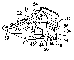
Referring now to the brackets shown in Figures 1 through 14, each
bracket body has labial, lingual, gingival, occlusal, mesial and distal
surface
portions 10, 12, 14, 16, 18 and 20 respectively, the corresponding orientation
directions, except for the mesial and distal, being shown in Figure 3 by
corresponding arrows. Each bracket is attached, as for example by laser
welding along its edges, to the gingival surface of a base 22 consisting of a
thin metal foil, the base in turn being attached to the gingival surface of a
metal wire mesh 24, the open pores of which facilitate the attachment of the
bracket to a tooth by cement in providing spaces to receive the cement.
Thus, all of the brackets are shown as ready for mounting on the respective
tooth by cementing, as increasingly is preferred, although they could also be
CA 02386801 2002-04-05
WO 02/24101 PCT/CA01/01301
-22-
mounted by fihe older method of attaching them to respective tooth-embracing
bands, which method is not illustrated. The body is provided with a mesial-
distal extending arch wire receiving slot 26 having its lingual side open, the
slot in this embodiment being of rectangular transverse cross section in a
gingival-occlusal, labial-lingual plane and having labial, gingival and
occlusal
surfaces 28, 30 and 32 respectively. The slot receives an arch wire 34 (see
Figures 5, 6, 1 0 and 1 1 ), which usually in the early stages of a procedure
is
of circular cross section (Figures 5 and 6), and of small enough diameter for
the bracket to slide freely along it once the arch wire is fully within the
slot
l0 and fully aligned therein. Subsequently the round arch wire usually is
replaced
by one of D-shape cross section (Figure 10) or rectangular cross section
(Figure 11 ).
Means for retaining the arch wire in the slot, and releasing it when
required, consist of a slot closure member indicated by arrow 36 that takes
the form of a selfjamming shutter, the member being mounted by a mesially-
distally extending pivot pin 38 that passes through the closure member and
the bracket body so that the member is movable about pivot axis 40 of the pin
between a slot open position (shown for example in Figures 2 and 7), in which
the open lingual slot side is unobstructed and therefore open, and a slot
closed position (shown in Figures 1, 4-6, and 10-1 5), in which the closure
member closes the open lingual slot side. The bracket body is provided with a
centrally disposed rectangular recess 42 that opens centrally to the body
occlusal surface portion 16 and also centrally to the part 44 of the lingual
surface portion 12 between the arch wire slot 26 and the junction between
the occlusal and lingual surface portions, this part 44 thus being divided
into
two equal mesial distal spaced sections by the intervening recess. The
jamming shutter consists of a pivot portion 46 that is always within the
recess
42, and through which the pivot pin 38 passes, and a slot closure portion 48
(indicated in Figure 3 only by arrow 48) the latter being movable with the
pivot portion. The slot closure portion extends mesially-distally with respect
to the device body and is the portion of the slot closure member that closes
CA 02386801 2002-04-05
WO 02/24101 PCT/CA01/01301
-13-
the open side of the arch wire slot, and also retains it in the slot closed
position, as will be described below. The part of the pivot portion between it
and the closure portion 48 extends lingually-labially and for convenience is
designated as an arm portion 50, this arm portion moving into and out of the
recess 42 respectively as the slot closure member is moved toward and away
from the slot closed position. The slot closure portion consists of a slot
closing part 52, which in this embodiment is divided into two mesially-
distally
spaced sections by an intervening rectangular slot 54 having its longer
dimension extending mesially-distally, and a bracket body engaging part 56
that extends equally mesially and distally from its centrally disposed
junction
with the lingual end of the arm portion. The mesial-distal dimensions of both
the slot closing part 52 and the body engaging part 56 are equal to the
corresponding mesial-distal width of the bracket body, so that in the slot
closed position the mesial and distal surface portions of the two parts are
flush with the mesial and distal surface portions 18 and 20 of the bracket
body.
The dimensions of the bracket body and of the slot closure member are
such that as the slot closure member is moved about the pivot axis 38 toward
the slot closed position, at first spaced sections of the slot closing part 52
rub
tightly against the corresponding immediately adjacent sections of the
bracket'
body lingual surface portion 44 with an interference fit rubbing and butting
engagement between them, such that the two sections of part 52 are flexed
toward the lingual againsfi the elasticity bf the material of the two
sections.
As the slot closure member moves further toward the slot closed position this
first rubbing engagement is succeeded by similar tight rubbing and butting
engagement between the two spaced sections of the body engaging part 56
and the corresponding immediately adjacent sections of body portion 44. The
two mesially-distally spaced sections of the lingual surface portion 44 also
have an interference fit between their engaged rubbing and butting surfaces
and the corresponding immediately adjacent engaged rubbing and butting
surfaces of body engaging part 56, such that the two sections of part 56 are
CA 02386801 2002-04-05
WO 02/24101 PCT/CA01/01301
-14-
also flexed toward the lingual against the elasticity of the material of the
body
engaging part, so that fihey are jammed against the body portion sections 44,
hence the reference to the slot closure member as a jamming shutter that
closes the arch wire slot. The result is that upon such first rubbing
engagement the closure member cannot be moved any further in the slot
closing direction without the exertion of sufficient force to flex .in the
lingual
direction first the slot closing part sections 52, and then the two end
sections
of the body engaging part 56. The slot closure part sections 52 wil( usually
be a little more flexible than the body engaging part sections 56 because of
the presence of the slot 54, so that the closing force required will increase
progressively as the slot closure member moves into the slot closed position
and the rubbing butting engagement of sections 52 is replaced by the rubbing
butting engagement of sections 56. Once in the slot closed position the
moving sliding interference fit engagement between the surfaces of sections
56 and those of surface portion sections 44 becomes a stationary butting
interference fit engagement between them, with the butting sections of the
body engaging part 56 permanently flexed lingually outward from the bracket
body to provide a corresponding labially-directed retaining force. Such
butting
engagement therefore positively retains the slot closure member in the slot
2o closed position, and movement thereof from that position requires
correspondingly forceful flexing of the body engaging part 56, and thereafter
of the slot closing part 58, in a the lingual direction away from the bracket
body against the resilience of the material of the body engaging part as it
slides over the bracket body lingual surface portions 44.
Such an effective method of retaining the slot closure member is
completely feasible with a product such as an orthodontic bracket in that the
number of openings and closings it is likely to experience during its working
life is relatively limited, so that the possibility of wear of the sliding
engaging
surfaces is minimal. Orthodontic brackets are already of necessity .
manufactured to very close tolerances (e.g. 0.00025mm or 0.0001 in) so that
the required rubbing, butting and jamming interference fit can easily be
CA 02386801 2002-04-05
WO 02/24101 PCT/CA01/01301
-15-
achieved. For example, in a bracket of the invention having a mesial distal
dimension (not including the base 22 or mesh 24) of 2.47mm (0.099in) and a
gingival occlusal dimension of 3:05mm (0. 1 12in), the slot closing part
sections 52 will measure occlusally-gingivally about the same. as the arch
wire
slot (slightly less is possible as is also slightly more so that it engages
the
body gingivally of the slot to provide a positive stop, while the bracket body
engaging part sections 56 of the jamming shutter will usually measure
0.42mm (0.01 7in) occlusally gingivally. The total mesial-distal length of the
part 56 will be equal to that of the bracket, while the mesial-distal lengths
and
labial-lingual thicknesses of the end sections 56 is dependent upon the
amount of flexing found to be necessary for the material used for the bracket
body. Thus; the mesial-distal lengths can in this case vary between 0.45mm
(0.018in) and 0.925mm (0.037in), while the labial-lingual thickness can vary
between 0.175mm and 0.425mm (0.007in and 0.017in); the amount of
flexing required of the end sections is of the order of 0.005-0. 01 mm (0.
0020.004in), and usually about 0.0075mm (0.003in), the elasticity of the
material being such that the sections fully recover upon their disengagement
from the bracket body. The amount of the deflection should not exceed the
yield point to prevent permanent deflection of the sections. A suitable
material for the bracket is 17/4PH stainless steel. In the event that some
brackets of a batch are found to open and close too easily this can be
corrected by the application of a very thin (e.g. 0.0025mm or. 0.001 in) hard
adherent coating to one or both of the engaging jamming surfaces.
In this embodiment the movement of the slot closure member from slot
closed to slot open position is produced with the aid of the recess 52, which
constitutes a tool-receiving recess elongated in the mesial-distal direction,
into
which the operator inserts the flattened end 58 (Figure 4) of an opening tool
which, upon rotation in the direction of the arrows 60 in Figure 4, moves the
slot closure member in the occlusal direction from the slot closed position. A
twist rotation of the tool of only about 45° is sufficient to move the
slot
closure member to the slot open position, no special instrument being required
CA 02386801 2002-04-05
WO 02/24101 PCT/CA01/01301
-16-
to move the closure member to the slot closed position. The gingival-occlusal
dimension (height) of the slot can be as small as 0.25mm (0.010in) and its
outer edges can be rounded so that it is impossible for a patient to gain a
purchase with a fingernail to open the bracket; typically an adult~fingernail
is
on average 0.4mm (0.016in) thick, while a thumbnail is usually on average
0.5mm (0.020in) thick. The labial-lingual length of the slot gingival surface
30
is greater than the corresponding length of its occlusal surface 32 by an
amount equal to the labial-lingual thickness of the slot closure part 50 and
the
body engaging part 56, so that the resultant overhanging part of the slot
gingival surface 30 provides a positive stop for the slot closure member
against which it buts to establish its fully closed position. In this
embodiment
the junctions 62 between intervening arm portion 50 and the body engaging
part 56 are of reduced mesial-distal dimension to thereby increase the
effective lengths of the body engaging sections of part 56 available for said
flexing. In slot closed position the lingual surface of the slot closure
portion is
flush with the corresponding lingual surface portion 12 of the bracket body,
and similarly the occlusal surfaces of the pivot portion 46 and slot closure
portion 48 are flush with the corresponding occlusal surface portion 16 of the
bracket body, so that in such position the bracket presents smooth, solid
exterior surfaces that minimize the likelihood of rough contact between the
brackets and the tongue and adjacent tissue of the mouth.
The brackets as so tar described are "passive", in that the only control
of tooth movement they could provide is by the interaction produced by
contact between the arch wire and the walls of the slot 26 through which the
wire passes. It is preferred in most procedures that the brackets be "active",
i.e. that they include some inherent means for controlling the attitude of the
bracket relative to the arch wire, and to that end each is provided within the
recess 42 with a flat attitude controlling spring member 64 having a fixed end
portion 66 that is fixed rigidly to the bracket body and a free end portion 68
extending into the arch wire receiving slot for engagement in a mesial-distal,
labial-lingual plane with an arch wire 34 in the slot, such engagement urging
CA 02386801 2002-04-05
WO 02/24101 PCT/CA01/01301
-17-
the arch wire toward the labial surface of the slot closure part and the
occlusal surface of the slot. The spring may be inserted in the bracket as it
is
assembled with the fixed end portion of the spring member sandwiched
between the bracket body and the foil member 22, the spring being provided
with a through aperture 70 and it, the bracket body, the foil member 22 and
the mesh layer 24 being attached to one another simultaneously by upsetting
a portion 68 of the bracket body and/or the foil member and/or the mesh layer
into the through aperture, as is shown in Figures 5, 7 10 and II. Figure 12
shows an alternative method of fastening the separate components together,
comprising a rivet 74 in place of the upset portion 68.
Figures 8 and 9 show a typical shape for such a spring before its
assembly into the bracket, the fixed end portion containing the aperture 70
being flat, while the free end portion comprises a first part that is concave
toward the occlusal about two different centers 76 and 78, followed by a part
l5 that is convex toward the occlusal about a center 80, and terminating in
the
part that engages the arch wire, this terminating part again being flat. The
force with which the spring engages an arch wire is dependent on the cross
section dimension of the arch wire, and the dimensions of the spring,
particularly its width and thickness; it can also be adjusted by forming the
2o spring with different amounts of preloading before the bracket is
assembled,
for example by adjustment of the profile of the spring, the force increasing
as
the radii of curvature about the axes 76-80 are decreased, and vice versa. A
preferred material for the springs used in the orthodontic devices of the
invention is the family of nickel-titanium alloys, commonly referred to as
25 superelastic shape recovery metal alloys, in that they can withstand
without
damage strains of as high as about 6-8%, as compared to the usual maximum
for stainless steels, the materials most commonly previously used, of 'about
0.5%. There is now adequate literature available as to the performance and
fabrication of springs using these materials and further explanation is not
30 required herein. Stainless steels of the required qualities will continue
to be
the material of choice for the device body and the jamming shutter.
CA 02386801 2002-04-05
WO 02/24101 PCT/CA01/01301
-18-
Figures 5 and 6 show the bracket used in conjunction with an arch wire
of round cross section, Figure 6 shovving a typical curvature for the wire in
the mesial distal plane. The wire contacts the slot closing part 52 at two
mesially distally equally spaced points A and is in turn contacted by the
spring
64 at a point B centrally between the points A. No change in the contacts
between the arch wire and the spring can take place without deflecting the
spring labially away from its most lingually forward position. Figure 1 O
shows the use of the bracket with an archwire of rectangular cross section
and of the largest dimensions (0.021 in X 0.025in) that can be fitted in the
slot, this gives a high degree of torque control with the spring providing a
strong braking action against mesial-distal sliding. Figure 11 shows the use
of the bracket with an arch wire of quarter round cross section and of
somewhat smaller dimension (0.020in); this gives full attitude control about
all
reference axes which pass through the arch wire slot centroid while at the
same time permitting low friction mesial distal sliding. As will be seen from
Figures 10 and 11 the free end portion of the spring member may be spaced
from the pivot portion 46 of the slot closure member (Figure 10) or may
engage the adjacent surface of the pivot portion (Figure 1 1 ). Preferably
this
engaged adjacent surface comprises a cam surface that is shaped to have a
protruding lobe 82 that, when the slot closure member is in slot open
position,
as shown in Figure 7, engages the spring free end portion and moves it out of
the arch wire receiving slot and thus out of contact with the arch wire,
facilitating both insertion and removal of the arch wire into and out of the
slot
during the course of a procedure. There is a resultant tendency for the spring
acting on the cam lobe 82 to urge the slot closure member toward the slot
closed position, but this is resisted sufficiently by the initial rubbing
engagement of the slot closing part sections 52 with the corresponding lingual
surface portion sections 44, so that the effect is to hold the slot closure
member in a suitable open position without moving too far toward the
occlusal, while preventing it from opening wider than is necessary. This
positive closing tendency does mean that once the arch wire is placed on the
CA 02386801 2002-04-05
WO 02/24101 PCT/CA01/01301
-19-
slot closure member it is "scooped" into the arch wire slot simply by moving
the slot c(osure~ member to slot closed position. Orthodontists often require
a
bracket to have a supplementary mesial-distal extending slot or passage for
use with a second arch wire or with other appliances, and such a slot 84 is
readily provided in the brackets of the invention in the part of the bracket,
body close to the lingual surface portion between the slot and the gingival
surface portion, as will be seen from Figures 5, 7, 10 and 11.
The brackets shown and described in association with Figures 1-12 are
intended for attachment to the lingual surface of an incisor or canine tooth,
1o which are characterized in that their labial-lingual dimension increases
progressively from the gingival to the occlusal. Figures 13 and 14 show a
typical application for such a bracket attached to the lingual surface of an
upper incisor 86 for use in a lingual procedure, while a standard Hanson
SPEED system bracket 88 is attached to the labial surface of the opposed
lower incisor 90 for simultaneous use in a labial procedure. Figure 13 shows
a common problem encountered in that the pafiient has a deep-bite
malocclusion in which the lower incisor is set too far lingually from the
upper
incisor for the teeth to meet properly when the jaw is closed, so that the
bite
is deeper than it should be. The brackets of the invention are particularly
suited for use with such a problem in that the gingival-occlusal dimension of
the bracket body decreases progressively from the lingual to the labial, and
this decrease has been made to correspond approximately to the average
increase in dimension from the occlusal to the gingival of an incisor or
canine
tooth. It will be seen that with the bracket attached to such a lingual
surface
the labial-lingual dimension of the bracket tooth combination is at feast
approximately uniform from the occlusal to the gingival, so that the bracket
occlusal surface lies in a mesial-distal, labial-lingual extending plane.
This,
together with the fact that in the slot closed position the occlusaf surface
portion of the slot closure member 48 is flush with the occlusal surface
3 o portion 16 of the bracket body means that the bracket is thereby able to
provide a combined occlusaf surface which is unobstructed and can constitute
CA 02386801 2002-04-05
WO 02/24101 PCT/CA01/01301
-20-
a bite plane against which the cutting edge of the lower tooth 90, i.e. at the
junction of its occlusal and labial surface portions, can engage during biting
action. Figure 14 shows the incisors 86 and 90 in their ideal relationship
when the malocclusion has been corrected and it will be noted that the lower
incisor no longer engages the lingual bracket. This structure therefore has a
number of practical advantages. The lingual brackets function as bite planes
to prevent the lower incisors from reaching their usual deep-bite malocclusion
over-closure, and can therefore replace the acrylic bite plates that are
placed
in the mouth to correct this. They also operate similarly to prevent any
1 o interference with the brackets 88 on the lower teeth while the
malocclusion is
present, so that they can be bonded to the teeth without fear that they will
be
detached as a result of over-biting. It also permits the posterior teeth to be
erupted during the procedure to further reduce the overbite.
Figure 15 shows an embodiment in which the structure of the pivot pin
l5 38 is changed from that shown in the embodiments of the preceding Figures
to assist in retaining the slot closure member in the slot closed position.
The
pin is divided midway along its length into two equal-length parts 38A and
38B, and the respective axes 40A and 40B of the pin parts are inclined in the
mesial-distal, labial-lingua! plane at a small angle (e.g. up to about
3°) from the
20 mesial-distal axis 40 toward the labial, the bore in the pivot portion 46
that
receives the pin parts being sufficiently large that with the slot closure
member in the slot open position the pin parts are straight, or nearly so (the
amount of any such bending that may be present being far too small to be
shown in the drawing), while with the member' in the fully slot closed
position
25 the ends of the pin parts within the pivot portion bore are bent toward the
lingual and press against the labial part of the bore wall, thereby
supplementing the jamming engagement of the slot closure member with the
bracket body. A typical diameter for the inclined holes in the bracket body is
0.30mm (0.012in), and the pin parts will be slightly oversize so that they
must
3o be forced into the holes and then secured against working free by laser
welding their outer ends to the bracket body. The two pin parts are therefore
CA 02386801 2002-04-05
WO 02/24101 PCT/CA01/01301
-21-
operative to urge the body en.gagin.g parfi 56 into its desired inference
engagement with the lingual surface portion parts 44 and will flex toward the
lingual as the slot closure member is moved to the slot open or slot closed
position; the adjacent ends of the two pin parts are rounded and spaced from
one another to permit this flexing movement to take place. The flexing that
takes place as the slot closure member is moved, and the flexing that is
required to maintain the slot closure member securely in the fully slot closed
position, is shared between the two sections of the body engaging part 56
and the two pin parts 38A and 38B, in a ratio determined by their respective
applicable dimensions and the elasticity of their respective materials. In a
bracket intended for labial procedures the pivot pin sections will be inclined
oppositely. Although such a structure is slightly more complicated it is able
to
accommodate the use of body parts with somewhat greater manufacturing
tolerances than structures with a single straight pin, which otherwise might
require some additional.manufacturing step, such as the post-assembly
coating described above. In addition, or alternatively, it enables the use of
much stiffer materials for the slot closure member and/or bigger labial-
lingual
dimensions for the body engaging part 56. In addition, or alternatively, it
can
help to ensure that the materials used are not stressed beyond their elastic
limit, although the use of the more expensive high elasticity nickel/titanium
alloys mentioned above for the small pin parts will ensure that fihis cannot
happen to them.
The structures of the invention are also applicable to brackets of the
type commonly used for labial procedures, and Figures 16-19 show examples
of their application to the type of bracket usually referred to as a siamese
twin
bracket. Such a bracket is provided with two mesially-distally spaced pairs of
tie wings 94 for the reception and retention of an external ligature, such as
a
soft metal wire or an elastomeric hoop or loop, and for the anchoring of
tension and compression members. The manner in which such orthodontic
3o elements are used is well known and does not require illustration or
further
explanation. The slot closure member 36 is disposed between the tie wings
CA 02386801 2002-04-05
WO 02/24101 PCT/CA01/01301
-22-
and operates exactly as described above for the brackets intended for lingual
procedures. The bracket body and its bonding base are of known rhomboidal
shape, as seen from the labial and lingual, the mesial and distal faces being
inclined at a small angle to a neutral gingival-occlusal extending plane. The
use of such rhomboid shaped brackets is preferred by many orthodontists and
is now well established. Because of the inclination the slot closure member is
offset toward the mesial, as seen in Figure 16, to prevent it fouling the
distal
occlusal tie wing as it is moved to slot open position. Preferably the bracket
is made active by incorporating therein between the bracket body and the
base 22 a short curved attitude controlling spring 64 whose profile can be
adjusted as required to provide any desired amount of pre-load. The active
bracket shown in Figure 18 includes provision to de-activate the ligating
spring 64 if desired; this is accomplished by pressing the spring hard
lingually
toward the mounting base until its free end is engaged behind a mesially-
distally extending ledge 96, from which inactive position, it can be retrieved
as
required by hooking the free end forward using the point of a standard sealer.
In the bracket shown in Figure 19 the slot closure member is also of rhomboid
shape so that offset thereof, as with the embodiment of Figure 16, is not
required. This does mean however that the pivot pin 38 must be inclined at
2o the same angle, and must be made shorter, so that the bore in which it
works
does not intrude into the arch wire slot. Such a bracket is best assembled by
making the body as two mirror image parts with registering blind bore holes,
the two parts being placed together with the pin between them and then
welded together along their butting edges.
Figures 20 through 29 shov~i the application of the invention to provide
new convertible buccal tubes, those illustrated by Figures 20-24, 26 and 29
being passive. Those shown in Figures 20-24 are intended for mounting on
the labial surface of a lower right first molar and have the arch wire slot 26
opening to the occlusal. The function and operation of the slot closure
3 o member 36 Damming shutter) in its movement between slot open and closed
positions, and in its positive retention in the slot closed position by the
CA 02386801 2002-04-05
WO 02/24101 PCT/CA01/01301
-23-
elasticity of the slofi closing part sections 56, is exactly the same as
described
above for the orthodontic brackets. Since in the tube of Figures 20-22 the
slot closure member moves labially and gingivally it is provided with a mesial-
distal extending tail part 98 thafi engages the bracket body to ensure that it
cannot open too far. One other difference in structure with the tube of
Figures 20-22 is that the slot 54 receiving the shutter opening tool 58 is
provided ~in the body of the tube and not in the slot closure member. As with
the lingual brackets, in the slot closed position the occlusal surface of the
slot
closure portion 48 is flush with the occlusal surface portion of the bracket
1o body to provide a smooth surface. Provision must usually be made for the
attachment to selected brackets of traction springs, elastic hoops and other
devices used in orthodontic procedures, and this may comprise a member,
such as a hook 100 shown in Figure 20, which can readily be attached to the
fixed portion of the tube body in a location where it will not foul the slot
closure member as it is moved between positions. An examination of Figures
13 and 14 will show that it is difficult to provide such attachment members
wifih the labial brackets first described, and this problem may be resolved by
employing a convertible buccal tube of the invention, which can be an active
tube as described below, in place of a bracket
Figures 23 and 24 also show a passive convertible buccal tube of the
invention intended for cementing to a lower right first molar, but in this
case
the arch wire opens to the labial, as with a bracket. The slot closure member
pivots about the pin 38 towards the labial and then toward the occlusal and
does not require any means, such as the tail part 98, to restrict the amounfi
by
which it opens. Figure 25 shows an active convertible buccal tube intended
for mounting on a lower second bicuspid, so that its labial-lingual dimension
varies less than with the previously-described tubes. The tube is made active
by the inclusion wifihin the tube body of a short curved attitude controlling
spring 64 that extends gingivally and protrudes into the arch wire slot afi
the
3o junction of its lingual and gingival surfaces. The spring can be
disengaged, so
that the tube is passive, by pressing it lingually until its free end engages
CA 02386801 2002-04-05
WO 02/24101 PCT/CA01/01301
-24-
behind a mesially-distally extending ledge 96, as with the siamese twin
bracket of Figure 18. Figure 26 shows another form of attachment device for
the buccal, tube of Figures 23-25, consisting of a mushroom-headed post 102
onto which tension members such as springs and elastomeric loops can be
anchored.
The convertible buccal tubes shown in Figures 27-29 are intended for
use with lower left central incisors and the jamming shutters thereof open by
moving to the lingual and gingival. The tubes are somewhat larger in gingival-
occlusal dimension than those,of Figures 20-26 to permit the provision of a
1 o supplementary mesial-distal extending slot 84, so that they are closer in
construction to a bracket than those prior buccal tubes. It may also be noted
that in the convertible tubes of Figures 20-26 any arm portion 50 is very
short
in length, to the extent that it has become almost vestigial; in the tubes of
Figures 27-29 the slot closure portion 48 merges with the pivot portion 46
without an intervening arm portion. In the active convertible tube of Figure
27, as with the bracket of Figures 1-12, the attitude controlling spring 64
engages a cam surface 82 of the pivot portion 46 and cooperates therewith to
assist in holding the jamming shutter in the slot closed position, and is
moved
by the cam surface as the slot closure member is moved toward the slot open
2o position out of the arch wire slot to ensure that it is disengaged from any
arch
wire 34 therein, so that the arch wire can more easily be removed and
inserted. In the convertible tube of Figure 28 a shorfi auxiliary spring 104
with
a predetermined amount of preload bears against the cam surface 82, and this
spring backs up the effect of the attitude controlling spring 64, which is
only
fully operative for this purpose when the tube is empty or when an archwire is
not deflecting it lingually. The slot closure member cannot be moved toward
the slot open position without deflecting at least the auxiliary spring. The
tube of Figure 29 is passive in the absence of an attitude controlling spring,
but is still provided with the.yauxiiiary spring 104 engaging the cam surface
82
3 o for the action described above.
CA 02386801 2002-04-05
WO 02/24101 PCT/CA01/01301
-z5-
Index of Reference Signs for the Drawings
Bracket body labial. surface portion
12 Bracket body lingual surface portion
14 Bracket body gingival surface portion
5 16 Bracket body occlusal surface portion
18 Bracket body mesial surface portion
Bracket body distal surface portion
22 Bracket body bass fail
24 Metal wire mesh
1026 Arch wire receiving slot
28 Slot labial surface
Slot gingival surface
32 Slot occlusal surface
34 Arch wire
1536 Slot closure member
38 Pivot pin for slot closure member
Pivot pin pivot axis
42 Bracket body recess .
44 Lingual surface portion parts engaged by slot closure
member
2 46 Slot closure member pivot portion
o
48 Slot closure member slat closure portion
Slot closure member arm portion
52 Slat closure member slot closing part
54 Slot for opening tool
2556 Slot closure member bracket body engaging part
58 Slot closure member opening tool
Arrows indicating direction of rotation of tool 58
62 Junctions between arm portion 50 and body engaging
part 56
64 Attitude controlling spring member
3 &6 Spring member fixed end
0
CA 02386801 2002-04-05
WO 02/24101 PCT/CA01/01301
-2 6-
68 Spring member fires end
70 Spring member through aperture
72 Upset portion fiastening spring member in
bracket body
74 Rivet fastening spring member in bracket
body
76178/80 Spring member arc centers
82 Protruding cam lobe on pivot portion 46
84 Supplementary mesial-distal extending slot
or passage
86 Upper incisor tooth
88 Hanson SPEED system bracket
90 Opposed lower incisor tooth
92 Angle between pin parts axes and mesial distal
axis
94 Twin siamese bracket tie wings
96 Spring disabling ledge
98 Taii part preventing excessive opening ofi slot closure member
100 Hook attachment member
102 Mushroom-headed attachment post
104 Auxiliary Spring