Note : Les descriptions sont présentées dans la langue officielle dans laquelle elles ont été soumises.
CA 02387093 2002-04-10
WO 00/21876 PCT/AU99/00868
-1-
LIQUID TRANSFER APPARATUS AND ADAPTORS
FIELD OF THE INVENTION
This invention relates to liquid transfer apparatus and adaptors for liquid
transfer apparatus.
The invention has particular application to liquid transfer apparatus and
adaptors for transferring
hazardous chemical liquids but it also has application to the transfer of safe
liquids where accurate
measurement is required.
There are many instances in which hazardous chemicals need to be transferred
from one container
to another, for example, when mixing poisons such as weedicides or pesticides
with water. Typically, an
operator pours the poison into a measuring container and then pours the
measured amount into the applicator,
whether it be a manually operated applicator or a motor driven or tractor
drawn applicator.
BACKGROUND ART
International patent application No. PCT/AU95/00869 describes apparatus for
and a method of
transferring hazardous liquids from one container to another utilising a
suction pump assembly with bubble
extraction chambers and a transfer vessel interposed between the bubble
extraction chambers and the
container of poison and arranged so that a desired amount of poison may flow
into the transfer vessel once
2 0 suction is applied without entering the pump assembly and then be
transferred to an applicator or other
container as required. Whilst this system works quite effectively in
commercial operations, it is not as compact
as is desirable and additionally the pump assembly is expensive to
manufacture. Furthermore, the system does
not lend itself to easy portability, transport or safe storage.
One object of the present invention is to provide liquid transfer apparatus
for use in transferring
hazardous liquids which is relatively inexpensive to manufacture. Another
object is to provide liquid transfer
apparatus which lends itself to easy portability and can be used by home
handymen as well as commercial
operators. It is another object to provide liquid transfer apparatus which
includes means for accurately
measuring quantities of liquid being transferred. Another object is to provide
liquid transfer apparatus which can
operate in conjunction with a container of liquid chemical in a closed system.
It is yet another object to provide
3 0 liquid transfer apparatus which can be easily dismantled for cleaning
purposes. It is still yet another object to
provide a system of transferririg hazardous liquids which reduces the
likelihood of spillage including
complementary components in conjunction with liquid transfer apparatus.
DISCLOSURE OF THE INVENTION
With the foregoing in view, this invention in one aspect resides broadly in
liquid transfer apparatus for
transferring liquid from one container to another container including:
a body defining an elongate liquid storage chamber having a liquid inlet at
one end and a fluid outlet
spaced longitudinally from said liquid inlet, a pump chamber having a fluid
inlet and a fluid outlet, a fluid flow
4 0 passage connecting said elongate liquid storage chamber and said pump
chamber via said fluid outlet of said
elongate storage chamber and said fluid inlet of said pump chamber, and a
handle, said body being formed of
CA 02387093 2002-04-10
WO 00/21876 PCT/AU99/00868
-2-
two halves joined together, each half defining part of said elongate storage
chamber and part of said pump
chamber and being constructed substantially of a thermoplastics material;
pump means mounted in said pump chamber for sucking air from said storage
chamber via said pump
chamber fluid inlet, and
valve means for selectively opening and closing said liquid inlet whereby
liquid may be allowed to flow
into said elongate storage chamber upon suction being applied to said elongate
liquid storage chamber by said
pump means and opening of said liquid inlet. Preferably, said handle includes
a passage therethrough
which forms at least part of said fluid flow passage and each half defines
half of said handle and said passage.
It is to be understood that the term "half" and its derivatives as used herein
unless clearly not appropriate is
intended to encompass complementary parts which when joined together form the
body or a component of the
body as described but which may not be actual mathematical halves.
Furthermore, terms such as upright, upper
and lower, top and bottom and the like are used for the purpose of description
and illustration of the invention
in the position it would normally be used for extracting liquid from one
container, but it is to be understood that
these terms do not limit the use of the invention to this position.
In another aspect this invention resides broadly in liquid transfer apparatus
for transferring liquid from
one container to another container including:
a body defining an elongate liquid storage chamber having a liquid inlet at
one end in a spigot portion
of said body for receiving liquid from the one container and for discharging
liquid to the other container, and a
fluid outlet spaced longitudinally from said liquid inlet, a pump chamber
having a fluid inlet and a fluid outlet,
2 0 a fluid flow passage connecting said elongate liquid storage chamber and
said pump chamber via said fluid
outlet of said elongate storage chamber and said fluid inlet of said pump
chamber, and a handle, said spigot
portion being adapted to sealingly cooperate with a complementary socket
provided in the one container;
suction pump means mounted in said pump chamber for sucking air from said
storage chamber via said
pump chamber fluid inlet, and
2 5 valve means for selectively opening and closing said liquid inlet whereby
liquid may be allowed to flow
into said elongate storage chamber upon suction being applied to said elongate
liquid storage chamber by said
pump means and opening of said liquid inlet.
Preferably, said fluid flow passage includes one or more liquid collection
chambers therein for collecting
liquid from moist air flowing therethrough, said one or more liquid extraction
chambers being arranged so that
3 0 liquid from moisture laden air flowing through said fluid flow passage may
collect therein.
Preferably, said valve is controlled by a trigger mounted adjacent said
handle.
Preferably, the apparatus includes a conduit connected to said pump chamber
fluid outlet for allowing
fluid sucked from said elongate storage chamber to flow to the one container
thereby allowing the apparatus
and the container to form a closed system for transfer from the container to
the storage chamber so that air or
3 5 fluid sucked from the storage chamber is discharged into the container as
liquid is removed. It is also preferred
that the conduit open adjacent said spigot portion and be adapted to cooperate
with the complementary socket
provided on the one container to allow the fluid to flow into the one
container as liquid is removed.
In another aspect the invention resides broadly in an adaptor for fitting to
an opening of a container and
adapted to co-operate with a spigot portion or other part of a pump or other
liquid transfer apparatus for filling
4 0 the apparatus with liquid from the container, the adaptor including:
CA 02387093 2002-04-10
WO 00/21876 PCT/AU99/00868
-3-
a socket portion having an entry adapted to receive therethrough the spigot
portion(or other liquid entry
part) of the liquid transfer apparatus for sealing engagement of the spigot
portion in said socket portion;
securing means on said socket portion or operatively connected to said socket
portion for securing said
socket portion to the container for liquid communication of the socket portion
with the container via the container
opening;
a liquid inlet in said socket portion for allowing liquid to flow into said
socket portion from the container,
the parts being so made and arranged that liquid may flow from said socket
portion to the liquid transfer
apparatus through the spigot portion (or other liquid entry part) upon vacuum
being thereto applied, the diameter
of said entry being greater than the diameter of the opening of the container.
Preferably, the socket portion has a fluid outlet spaced from the fluid inlet
which is connected to a
conduit or other flow passage through which fluid can flow into the container.
Suitably, the fluid outlet is adapted
for sealed fluid communication with a complementary fluid outlet on the pump
or other liquid transfer apparatus
with which the adaptor is to be used whereby air, vapour or other fluid
expelled from the pump can flow through
the fluid outlet and into the container thereby allowing the pump and the
container to form a closed system
during transfer of liquid from the container to the pump. Preferably the fluid
flow passage opens within the
bounds of the securing means so that fluid flowing therethrough will flow into
the container via the container
opening.
Preferably, the adaptor is constituted by two main components with the socket
portion being formed
in one component which is fitted within the other component with a space
formed therebetween providing the
2 0 flow passage for fluid flow from the fluid outlet to the container
mentioned previously. Suitably, in such form,
the securing means is provided on the other component and preferably is a
threaded portion adapted to engage
a complementary threaded portion on the container. It is also preferred that
the adaptor include a threaded
closure or other suitable alternative for closing the entry to the socket
portion and that the one component
include a complementary threaded portion or equivalent for cooperating with
the closure. Advantageously, such
2 5 arrangement allows the adaptor to remain connected to the container while
still being able to be closed.
Preferably the adaptor includes residue limiting means mounted in the socket
portion and adapted to
co-operate with the spigot portion of a pump engaged in the socket portion so
as to restrict the amount of
surtace area of the spigot portion which is contacted by liquid flowing from
the container to the pump. Preferably
the residue limiting means includes a plate-like component adapted to engage
with the end face of the spigot
3 0 portion to form a cover thereon.
In another aspect this invention resides broadly in an adaptor for a container
for adapting an
opening of the container to receive the spigot portion of liquid transfer
apparatus as previously described, the
adaptor including:
a wall defining a socket portion adapted to receive the spigot of the liquid
transfer apparatus, an inlet
3 5 in said wall for allowing liquid to flow into said socket portion and an
outlet in said wall for allowing fluid to flow
from said socket portion into the container, said fluid outlet being spaced
from said inlet and the inner face of
said wall being adapted to sealingly engage with spaced apart sealing means on
the spigot on each side of said
outlet to isolate said outlet from said inlet, and
securing means on said socket portion or operatively connected to said socket
portion for securing said
4 0 socket portion to the container for liquid communication of the socket
portion with the container.
CA 02387093 2002-04-10
WO 00/21876 PCT/AU99/00868
-4-
In another aspect the invention resides broadly in an adaptor for fitting to a
threaded opening of a
container and adapted to co-operate with another product for the transfer of
liquid from the container to or via
the other product, the adaptor including;
a cap portion adapted to engage with the rim of the container opening;
a plurality of circumferentially spaced apart thread engaging components
moveably connected to and
depending from said cap portion and adapted to engage with respective
circumferentially spaced portions of
the thread about the opening, and
adjustment means operatively connected to said thread engaging components and
adapted to adjust
the position of said thread engaging components radially in and out for
engagement with openings of different
size.
It will be seen that the adaptor may be fitted to a plurality of different
sized and/or different types of
threaded container openings and adapted to co-operate with a desired
complementary product. The adaptor
has particular application for fitting to plastic four litre and twenty litre
containers which at present are produced
with a multitude of different sized openings and different types of threads.
In many cases, the differences in
opening size and type of thread is immaterial because the contents are simply
poured from the container into
another receptacle, for example from a four litre plastic oil container into
an engine. However, the transfer of
hazardous liquids from one container to another container or other receptacle
must be undertaken with great
care so that spillage is avoided. Additionally, in many cases great care must
also be taken so that the desired
amount of hazardous liquid is accurately measured and transferred.
Advantageously, the adaptor in a preferred
2 0 form cooperates with the adaptor for transferring hazardous chemical
liquids from the container to the transfer
apparatus for spill-free transfer.
Preferably the thread engaging components are spaced apart in the direction
away from the cap portion
so that they can engage with circumferentially spaced portions of the same
thread form. It is also preferred that
the thread engaging components or at least a portion of each of them be
flexible towards and away from the
2 5 cap portion whereby they are self-adjusting to accommodate threads of
slightly different pitch, for example, they
may be constructed of a low durometer material. It is also preferred that the
thread engaging components be
so made and arranged that the area of contact with the threads of the threaded
opening increases as they are
adjusted to suit openings of greater diameter so that they can bear a greater
tightening force.
Preferably the cap portion has an integrally formed upstanding wall on the
opposite side to the thread
3 0 engaging components, which has formed therein a socket or has fitted
therein an adaptor with a socket formed
therein, the socket in either case having an entry adapted to receive
therethrough the spigot portion(or other
liquid entry part) of liquid transfer apparatus as previously described.
In another aspect this invention resides broadly in an adaptor for fitting to
an aperture provided in a wall
of a storage tank for receiving the spigot portion of liquid transfer
apparatus as previously described, the adaptor
35 including:
a socket portion having an elongate passage extending therethrough with an
entry at one end adapted
to receive therethrough the spigot portion of the liquid transfer apparatus
for sealing engagement in the
passage, and an outlet at the other end for allowing liquid to flow out of
said socket portion into the storage tank
to which the adaptor is fitted;
4 0 deflector means depending from said socket portion and extending across
the passage for deflecting
liquid sideways of said passage;
CA 02387093 2002-04-10
WO 00/21876 PCT/AU99/00868
-5-
closure means for selectively closing said entry;
a flange extending outwardly from said socket portion intermediate said entry
and said outlet and an
external thread on a portion of said socket portion between said flange and
said outlet, and
a nut adapted for threaded engagement with said threaded portion, the parts
being so made and
arranged that the threaded portion may be passed through the aperture in the
storage tank wall and the flange
engaged against one face thereof while the nut engages against the other face
to secure the adaptor to the
storage tank wall. Preferably, the socket portion has an external thread on
the other side of the flange for
receiving thereon a threaded cap for closing the entry.
In another aspect this invention resides broadly in the combination of liquid
transfer apparatus as
previously described for transferring liquid from one container to another
container and an adaptor as previously
described for adapting an opening of the one container for cooperation with
the liquid transfer apparatus.
In another aspect this invention resides broadly in a carry case for a liquid
transfer apparatus as herein
described including:
a first part and a second part connected to said first part for pivoting
movement from an open position
in which the liquid transfer apparatus can be placed in and removed from one
of said first and second parts and
a closed position in which the liquid transfer apparatus is enclosed within
said first and second parts, one or
both of said first and second parts having a recess
adapted to receive the end portion of the body having the liquid inlet to the
elongate storage chamber, said
recess being adapted to cooperate with the end portion to hold the apparatus
in an upright attitude. In a
2 0 preferred form in which the end portion of the body is conical in shape,
the recess is formed in a corresponding
conical shape adapted to receive the end portion and hold the apparatus
upright.
BRIEF DESCRIPTION OF THE DRAWINGS
In order that the invention may be more readily understood and put into
practical effect, reference will
now be made to the accompanying drawings which illustrate preferred
embodiments of the invention and
wherein:
Fig. 1a is a plan view of liquid transfer apparatus according to the
invention;
Fig. 1 b is a sectional elevation of the apparatus of Fig. 1 along line 1A -
1A;
3 0 Fig. 1 c is a plan view of the body of the apparatus of Fig. 1 a;
Fig. 1 c;
1 d;
Fig. 1d is a sectional elevation of the body of the apparatus of Fig. 1a along
the line 1A - 1A shown in
Fig. 1e is a sectional plan view of the body of the apparatus of Fig. 1 a
along line 1 B - 1 B shown in Fig.
Fig. 1f is a sectional plan view of the body of the apparatus of Fig. 1a along
line 1C - 1 C shown in Fig.
1 d;
Fig. 1 g is a sectional plan view of the body of the apparatus of Fig. 1 a
along the line 1 D - 1 D shown
in Fig. 1d;
Fig. 1h is a sectional plan view of part of the body of Fig. 1c showing the
joint between the two moulded
4 0 halves;
Fig. 2a is a plan view of a pump chamber liner of the apparatus of Fig. 1a;
CA 02387093 2002-04-10
WO 00/21876 PCT/AU99/00868
-6-
Fig. 2b is an elevation of the liner of Fig. 2a;
Fig. 3a is a plan view of the upper pump chamber cap of the apparatus of Fig.
1 a;
Fig. 3b is a sectional elevation of the upper pump chamber cap of Fig. 3a;
Fig. 4a is a plan view of the lower pump chamber cap of the apparatus of Fig.
1 a;
Fig. 4b is a sectional elevation of the lower pump chamber cap of Fig. 4a;
Fig. 5a is a plan view of a thread insert for the cap of Fig. 3a;
Fig. 5b is an elevation of the thread insert of Fig. 5a;
Fig. 6a is a plan view of a bucket component for the pump assembly of the
apparatus of Fig. 1a;
Fig. 6b is an elevation of the bucket component of Fig. 6a;
Fig. 7a is a plan view of the plunger rod of the apparatus of Fig. 1 a;
Fig. 7b is an elevation of the plunger rod of Fig. 7a;
Fig. 8a is a plan view of the trigger of the apparatus of Fig. 1 a;
Fig. 8b is an elevation of the trigger of Fig. 8a;
Fig. 9a is an end elevation of the plunger rod of the pump assembly of the
apparatus of Fig. 1 a;
Fig. 9b is an elevation of the pluger rod of Fig. 9a;
Fig. 10a is a plan view of an adaptor according to the invention for use with
the apparatus of Fig. 1a;
Fig. 10b is a sectional elevation of the adaptor of Fig. 10a along a diametral
plane;
Fig. 11a is a bottom view of an adaptor body for use with the apparatus of
Fig. 1a;
Fig. 11b is an elevation of the adaptor body of Fig. 11a;
2 0 Fig. 11 c is an end elevation of the adaptor body of Fig. 11 a;
Fig. 11d shows a sectional view of the adaptor body of Fig. 11 a with a
washer, a nut and a cap shown
in-line for assembly with the adaptor body;
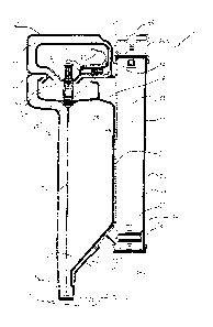
Fig. 12 is a representation of the adaptor of Fig. 11d fitted to a spray tank
with the transfer apparatus
of Fig. 1a engaged therewith;
2 5 Fig. 13a is a plan view of a carry case with the apparatus of Fig. 1 a
superimposed to show its position
therein;
Fig. 13b is a side elevation of the carry case of Fig. 13a;
Fig. 13c is an end view of the carry case of Fig. 13a showing the apparatus
superimposed therein;
Fig. 14 is an elevation of the carry case of Fig. 13a and the apparatus of
Fig. 1a engaged therewith
30 using the carry case as a stand;
Fig. 15 is a sectional elevation of part of the arrangement shown in Fig. 14;
Fig. 16 is a sectional elevation along a diametral plane of another adaptor
according to the invention
showing part of the inlet spigot of transfer apparatus similar to that of Fig.
1 a but with a larger spigot portion
engaged therewith;
3 5 Figs. 17 and 18 show the same sectional views of the two main components
of the adaptor of Fig.16
prior to assembly.
Fig. 19a is a plan view of another adaptor according to the invention without
hidden detail;
Fig. 19b is a sectional elevation of the adaptor of Fig. 19a along line 19a-
19a;
Fig. 19c is the same elevation as in Fig. 19b except that the socket body part
of the adaptor has been
4 0 removed for clarity;
Fig. 19d is a plan view of the adaptor of Fig. 19a having some components in
hidden detail;
CA 02387093 2002-04-10
WO 00/21876 PCT/AU99/00868
-7-
Figs. 20a, 20b and 20c are part sectional plan views of the adaptor of Fig.
19a illustrating use with
different sized container openings with threads 207, 208, and 209
respectively;
Fig. 21 is a pictorial representation of the thread engaging component of the
adaptor of Fig. 19a;
Fig. 22 is a pictorial representation of another adaptor according to the
invention fully assembled;
Fig. 23 is a pictorial representation of the adaptor of Fig. 22 with various
components in-fine for
assembly;
Fig. 24 is a plan view of the cap part of the adaptor of Fig. 22;
Fig. 25 is an elevation of the cap part of Fig. 24;
Fig. 26 is a sectional elevation of the adaptor of Fig. 22 along a diametral
plane;
Fig. 27 is a plan view of the adaptor of Fig. 22 projected from Fig. 26;
Fig. 28a is a part plan view of the adaptor of Fig. 22 showing some of the
components in hidden detail;
Fig. 28b is a part sectional elevation of an adaptor of Fig. 22 along a
diametral plane with the socket
body part of the adaptor removed for clarity;
Fig. 29 is an elevation of the liquid transfer apparatus of Fig. 1a in use
fitted to the adaptor of Fig. 22,
and
Fig. 30 is a sectional plan view of an alternative adaptor according to the
invention for use with an
internally threaded opening.
DETAILED DESCRIPTION OF THE DRAWINGS
The liquid transfer apparatus 10 illustrated in Figs. 1 a and 1 b includes a
body 11 formed by joining two
halves 11 a and 11 b along a seam line coincident with the section line 1 A -
1A. Each half is constructed of a
thermoplastics material and is formed by an injection moulding process and the
two halves are subsequently
joined along the seam line in known manner to form the body.
The body defines an elongate liquid storage chamber 12 having a liquid inlet
13 in a spigot portion 14
and a fluid outlet 16 spaced longitudinally from the liquid inlet, a pump
chamber 17 adjacent the elongate
storage chamber having a fluid inlet 18, a fluid outlet 19, and a handle 21
above the liquid storage chamber with
a flow passage 22 therethrough and connected to the fluid outlet 16 and the
fluid inlet 18.
The lower end portion of the liquid storage chamber is conical in form (an
eccentric cone) and has
measuring marks or graduations molded on the body ( as shown in Fig. 12) so
that the amount of liquid stored
therein can be easily determined. As more clearly shown in Fig. 1e the pump
chamber 17 is substantially
circular in cross-section but has an elongate recess 20 extending from the
fluid inlet 18 almost to the lower end
17b of the pump chamber to provide a flow passage for air sucked from the
liquid storage chamber as will be
described later. A top cap 24a and a bottom cap 24b are screwed to the upper
and lower ends of the pump
chamber and can be easily removed to allow the pump assembly (which will be
described later) to be removed
for cleaning and maintenance purposes. Each cap is moulded in two parts, the
thread being formed on one part
24c which is then glued to a second part 24d in the case of the top cap as
shown in Figs. 3a and 3b and 24e
in the case of the bottom cap as shown in Figs. 4a and 4b.
A pump assembly 24 is mounted in the pump chamber and arranged to suck air
from the liquid storage
4 0 chamber via the fluid flow passage 22 thereby creating a vacuum in the
liquid storage chamber whereby liquid
may flow thereinto via the inlet 13 from a container of liquid in which the
inlet is immersed or connected. A valve
CA 02387093 2002-04-10
WO 00/21876 PCT/AU99/00868
_g_
assembly 26 is arranged to open and close the inlet 13 upon operation of a
trigger mechanism 27 as will be
described later.
Two liquid collection chambers (sometimes called bubble extraction chambers)
28 and 29 are provided
in the fluid passage 22, one being near the fluid outlet 16 of the storage
chamber and one being near the inlet
to the pump chamber 18. The liquid collection chambers are arranged so that in
the upright in-use position as
shown in Fig. 1 b, undesirable liquid entrained in the air flowing through the
flow passage 22 will settle in the
liquid collection chambers. Advantageously this prevents the ingress of
hazardous chemical into the pump
chamber or the pump assembly.
The pump assembly 24 has a pump cylinder 33 constructed of a plastics material
and a plunger
assembly 34 slidably mounted therein to form a push-pull type plunger pump.
The plunger assembly includes
a plunger rod 36 and a pump bucket and valve assembly 37 mounted on its lower
end. At the other end a
handle is secured to the plunger rod externally of the pump cylinder for
moving the plunger rod up and down
in the normal manner. The pump cylinder has a plurality of apertures 38
provided near its lower end as more
clearly shown in Fig. 2b and is a neat fit in the pump chamber 17, the pump
cylinder and the recess 20 together
defining a flow passage from the fluid inlet 18 to the apertures 38 whereby
air may flow from the liquid storage
chamber 12 into the pump cylinder via the valve assembly 39 which is secured
to the bottom cap 24b.
A fluid outlet 41 is provided in the top cap and is arranged to receive a
plastic tube (shown in
phantom)whereby air or air and liquid mixture discharged from the pump chamber
can flow via the tube to a
return passage 42 formed in the body adjacent the lower end of the storage
chamber to the container from
2 0 which liquid is being drawn. The passage 42 terminates at the spigot
portion 14 as will be described later.
The valve assembly 26 includes a valve rod 46 which extends longitudinally
through the storage
chamber from the trigger 27 (which is mounted in a cavity 47 formed by the
handle 21) to a valve head 48
having a rubber O-ring 48a at the inlet 13. The trigger is arranged to move
the valve rod down and up as the
trigger is pulled and released to move the valve head into and out of
engagement with the spigot portion 14 to
2 5 close and open the inlet 13, and is biased to the up position in which the
valve head closes the inlet by a spring
50. A second valve head 49 is provided on the valve stem for opening and
closing a pair of liquid return
passages 51 and 52 between the liquid collection chambers 28 and 29 and the
liquid storage chamber 12. Upon
the valve stem reaching a predetermined open position the valve head is clear
of the passage thereby allowing
the return of liquid collected in the collection chambers to the liquid
storage chamber. A third valve head 56 is
3 0 provided on the valve stem near the trigger and is arranged to open and
close a passage 57 connecting the
collection chambers 51 and 52 to the open hand cavity 47 so that vacuum in the
liquid storage chamber can
be released to atmosphere. The trigger includes a pin and slot mechanism 66 in
which the pin is slidably
mounted in the slot and can be selectively engaged with the shoulder of the
body for holding the valve stem in
the down position thereby preventing deformation of the ring 48a while not in
use.
35 The spigot portion 14 tapers away from the liquid storage chamber to the
inlet 13 and has two spaced
apart O-ring grooves 61 and 62 provided in the outer face thereof for
receiving O-rings 61a and 62a (not
shown). The return passage 42 opens into a recess 65 via an opening 63 located
between the two o-ring
grooves, the recess extending around the spigot portion to distribute
returning fluid thereabout so that it can
return to the container as will become clearer later. The spigot is shaped and
sized for engagement with the
4 0 adaptor 70 illustrated in Figs. 12a and 12b as will now be described and
other adaptors also described later.
CA 02387093 2002-04-10
WO 00/21876 PCT/AU99/00868
_g_
The adaptor 70 illustrated in Figs. 10a and 10b is adapted for mounting to two
different sized standard
chemical container openings and includes an upper portion 71 having a screw
thread 72 formed on an outer
face thereof for screw-threadedly receiving a closure (not shown). A socket
portion 73 depends from the upper
portion and has an inner face 73a and an outer face 73b while a liquid inlet
portion 74 is provided at its lower
end 75. A tube 76 is connected to the inlet portion 74 and is adapted to
extend to the bottom of a container to
which the adaptor is fitted. A plurality of apertures 77 are provided in the
socket portion 73 to allow flow of liquid
from the socket portion back into the container. The socket portion is shaped
to receive therein the spigot 14
of the apparatus 10 with the O-rings 61a and 62a engaging against the inner
face 73a of the socket portion
above and below the apertures 77 respectively so that the outlet 63 can
communicate with the apertures 77 in
isolation from the inlet 13. A threaded skirt 78 depends from the upper
portion 71 and is adapted to screw
threadedly engage with a standard sized container outlet but in another
embodiment an additional threaded skirt
is provided outside skirt 78 and concentric therewith to suit a larger
threaded container opening.
It will be seen the combination of the liquid transfer apparatus 10 and the
adaptor 70 such that the
spigot portion 14 is sealingly engaged in the socket portion allows liquid to
be drawn from a container into the
liquid storage chamber 12 by operation of the pump assembly and air pumped
from the liquid storage chamber
by the pump assembly 24 can be discharged through passages 41 and 42 and into
the container thereby
forming a closed system.
In use, the closure of a standard 20 litre drum (or other size as desired) is
removed and the adaptor
70 is screwed to the container opening with the tube 76 extending to the
bottom of the drum. The liquid transfer
2 0 apparatus 10 is then held with the spigot 14 engaged in the socket portion
73 with the O-rings engaging with
the inner face 73a to form a seal. The pump plunger 36 is then moved up and
down in the normal manner so
as to create a vacuum in the liquid storage chamber 12 whereupon the trigger
27 can be pulled to open the
valve head 48 thereby allowing liquid to flow from the drum into the spigot
portion 73 and then through the inlet
13 into the liquid storage chamber 12. The liquid storage chamber has
measuring graduations or marks (as
shown in Fig. 12)provided on the wall so that an operator can accurately
measure the amount of liquid drawn
into it. Upon the required amount of liquid being drawn into the liquid
storage chamber, the trigger is released
and the apparatus is removed from the adaptor and transferred to the
applicator (or other container) in which
the liquid is to be discharged. Once in the desired position the trigger 27 is
pulled again to move the valve 48
out of the inlet 13 whereupon the liquid in the storage chamber is released
and flows out through the inlet 13.
3 0 Further pulling of the trigger causes the valve head 49 to open the
passage between liquid collection chambers
51 and 52 and the liquid storage chamber 12 so that any liquid collected
therein can flow into the liquid storage
chamber. Coincidentally the valve head 56 moves downwardly to allow the
collection chambers to vent to
atmosphere through passage 57.
The adaptor 80 illustrated in Figs. 11a to 11d is adapted for mounting to a
container such as a broom
3 5 spray tank into which liquid chemical is to be discharged by liquid
transfer apparatus such as that shown in Figs.
1 a and 1 b. The adaptor is similar in form to adaptor 70 illustrated in Figs.
10a and 10b and reference can be
made to the description relating to that adaptor for a clearer understanding
of its construction, although it should
be noted that this adaptor is for discharge purposes from the transfer
apparatus. The adaptor includes an upper
portion 81 having a screw thread 82 formed on an outer face thereof for screw-
threadedly receiving the closure
40 83 shown in Fig. 11d in the same manner as adaptor 70. A socket portion 83
depends from the upper portion
and has an inner face 83a and an outer face 83b with a thread 83c formed
thereon. A bridge portion 85
CA 02387093 2002-04-10
WO 00/21876 PCT/AU99/00868
-10-
depends from the socket portion to create opposed side openings 86 through
which liquid can enter the spray
tank to which the adaptor is fitted.
The socket portion is shaped to receive therein the spigot 14 of the apparatus
10 but in this case a good
seal is not required as the apparatus will not be used in its suction mode. It
will be seen that once the spigot
portion is fitted in the socket portion the trigger 27 can be pulled to open
the inlet 13 so that liquid in the storage
chamber 12 can be released into the socket portion of the adaptor and then
flow into the spray tank via the side
openings 86. It will be appreciated that the bridge portion 85 acts to deflect
liquid sideways to spread the liquid
(in the case of a chemical) across the surface of the water in the spray tank.
A flange 87 extends outwardly from the outer face of the socket portion and is
adapted to abut the outer
face of the spray tank (or other container) and a washer 88 and nut 89 are
adapted to be fitted to the thread 83c
from the inside of the spray tank so that the wall of the spray tank is
effectively clamped between the washer
and the flange as shown in Fig. 12.
The liquid transfer apparatus can be stowed for easy portability in the carry
case 90 illustrated in Figs.
13, 14, 15 and 16. The carry case includes a recess 91 provided therein having
a complementary shape to the
lower end portion of the elongate storage chamber to provide a stand for the
liquid transfer apparatus when not
in use. A smaller recess 92 is provided in the carry case to support the lower
end cap of the pump chamber
when in the standing position.
The adaptor 110 illustrated in Fig. 16 includes two main components 111 and
112 illustrated in Figs.
17 and 18 which are moulded from a plastics material and are both
substantially cylindrical in form. The first
component 111 has a socket portion 113 adapted to receive therein the spigot
portion 14 of liquid transfer
apparatus similar to that shown as item 10 in Figs. 1 a, except that the
spigot portion has a greater diameter,
which is adapted to suck liquid from the socket portion for transfer to
another container, for example, the storage
chamber of a boom spray and the same reference numerals will be used when
referring to the larger transfer
apparatus as for apparatus 10. It will be seen that the spigot has two
circumferentially extending O-ring grooves
2 5 61 and 62 in which O-rings (not shown) are mounted for sealing engagement
with the inner face 113a of the
socket portion. It will also be seen that the pump spigot has a return fluid
outlet 63 which is aligned with the fluid
return outlet 119 provided in the wall of the socket portion. A plurality of
such outlets are spaced around the wall
to allow increased return fluid flow and a circumferential recess 65 is formed
in the pump spigot to provide a
flow path for returning fluid from the outlet 18 to any of the outlets 119 as
previously described.
3 0 At its lower end, the first component has a liquid inlet 122 to which a
tube 120 (which corresponds to
tube 76 in Fig. 10b) is connected and which is a suitable length for reaching
the bottom of the container to which
the adaptor is to be fitted. The tube and the inlet are adapted to allow free
flow of liquid from the container into
the socket portion 113 from where it can flow into the pump via the pump
liquid inlet 13. The pump inlet is
selectively closed by the valve head 48 which engages with the bottom end 25
of the spigot portion and is
3 5 operated by a trigger 27 on the pump handle for downward movement against
a spring bias (also in the handle)
to move the bottom cap to the open position to allow liquid to enter the pump
via opening 23. In this case the
rubber ring 48a is replaced by an O-ring 48b for sealing as previously
described.
A plunger assembly 128 is mounted in the lower end of the first component 111
and includes a plunger
head 129 which is mounted on a spring 130 for up and down movement in the
socket portion. Spaced apart lugs
4 0 129a are provided on the periphery of the plunger head thereby forming
flow passages between the plunger
head and the inner face of the socket portion. In use, the valve head 48 of
the pump spigot 14 engages against
CA 02387093 2002-04-10
WO 00/21876 PCT/AU99/00868
-11-
the upper face of the plunger head as the spigot is being inserted into the
socket portion and the spring 130
holds it in place so that liquid being drawn into the pump through the inlet
13 via the socket portion does not
come into contact with the bottom face of the plunger 124.
The second component 112 has an upper sleeve portion 141 and a lower securing
portion 142 and as
more clearly illustrated in Fig. 16, when the first component is mounted
within the second component an annular
space 145 is formed between the socket portion and the sleeve portion with the
fluid outlet 119 opening into
this annular space and the annular space thereby providing a fluid flow
passage for flow of return fluid to the
container along the flow path marked as item 143. The first component has a
bead 32 extending about the outer
face of the socket portion near its upper end which engages in a complementary
groove 144 formed about the
inner face of the sleeve portion near its upper end to secure the two main
components together. At its lower
end, the inner component has four spaced apart lugs 131 thereon which engage
with the inner face of the
sleeve portion 141 to centralise the first component therein. It will be
appreciated that the two components can
be easily die-moulded and fitted together to form a simple adaptor unit vvhich
can be screwed to an external
thread of a container outlet. For this purpose two alternative threads 146 and
147 are provided on the securing
portion 142. Thread 146 is formed to engage a standard size thread of a four
litre container and it will be seen
that the diameter of the entry 115 is greater than the inner diameter of the
standard container opening to which
the adaptor can be fitted with thread 146. Thread 147 is adapted to engage
with the standard size external
thread of a twenty litre container.
The adaptor 110 may be fitted to the container outlet of a standard four litre
container by screwing the
2 0 thread 146 onto the complementary thread of the container whereupon the
pump spigot 14 can be engaged
in the socket 113 as shown and the underside face of the bottom cap then
engages the upper face of the
plunger head. The valve head 48 can then be pushed downwardly to open the
inlet 13 with the valve head
being forced against the upper face of the plunger head. The pump can then be
operated to suck liquid out of
the container through the inlet tube 120 and the liquid inlet 122 so that
liquid flows into the socket portion
2 5 around the lugs 129a and then into the pump through the inlet 13. As the
pump is operated, air, vapour or other
fluid being forced from the collection chamber in the pump can flow through
the pump return fluid outlet 63 and
the fluid outlet 119 into the annular space 145 and then into the container
via the flow path 143 in a similar
manner to that described earlier in relation to adaptor 70.
It will be seen that the diameter of the socket portion 13 is such as to
receive a pump with a bigger
3 0 spigot 14 than would be possible with adaptor 70. Advantageously a greater
diameter spigot portion allows a
faster flow rate for liquid into the pump.
The adaptor 210 illustrated in Figs. 19a to 21 includes a cap part 211 from
which seven thread
engaging components 212 depend and which are spaced circumferentially about a
cap axis 215, a cover 213
which is operatively connected to the thread engaging components for adjusting
their respective positions, and
35 a socket body 214 which is secured to the cap part and extends through a
centrally located aperture 216
provided therein for communication with liquid in the container to which the
adaptor is to be fitted.
The cap part has a disk-like cap portion 217 which is adapted on its underface
to sealingly engage the
rim of an externally threaded container, and a sleeve portion 218 extending
upwardly from the upper face of the
cap portion to provide a housing for the socket body 214. A sealing ring or
washer may be fitted to the
4 0 underface of the cap portion to effect better sealing with the container
rim if desired and in this embodiment an
annular recess extends about the aperture 216 for holding a flat sealing
washer. Seven apertures 219 are
CA 02387093 2002-04-10
WO 00/21876 PCT/AU99/00868
-12-
provided in the cap portion 217 equally spaced about the cap axis near its
periphery and the thread engaging
components are pivotally mounted to the respective apertures as will be
described in more detail later.
Each thread engaging component 212 includes a lobe 221 which has an arcuate
edge face 222 with
a bevelled lower portion 222a adapted to engage in a thread recess or under a
thread form. The lobe is
mounted on one end of a small shaft or stem 223 and a crank 224 is mounted on
the other end of the shaft with
a crank pin 226 extending from the crank arm. The stem of the respective
thread engaging components extends
through its respective aperture 219 so that the lobe 221 is below the cap
portion and the crank arm 224 and
crank pin 226 are above the cap portion. It will be appreciated that orbiting
of the crank pin 226 about the shaft
axis 225 will be effective to move the edge 222 of the lobe towards and away
from the axis 215 for engagement
of the respective thread engaging components with the threads of container
openings of different sizes. In
another embodiment, the bevelled lower portion 222a is replaced by a plurality
of laterally extending flexible
fingers 227 (not shown)which are adapted to self mould around the thread form
of the container opening.
Orbiting of the respective crank pins about their respective shaft axes 225 is
controlled by the cover
213 which is rotatably mounted on the sleeve 218 resting on a sleeve like
washer 220 and being retained on
the sleeve by an integrally formed bead 218a. The cover has seven curved slots
225 which slidably receive
therein the crank pins of the respective thread engaging components and it
will be seen that partial rotation of
the cover about the axis 15 causes orbiting of the crank pins about their
respective stem axes 225. Also in this
embodiment the components are arranged to be secured at a selected thread
engaging position by a securing
mechanism(not shown) but similar to that described later in relation to Figs.
22 to 28b.
2 0 The respective thread engaging components are spaced from the cap portion
217 by different amounts
in a helical or stair like manner in order to approximate a thread form and to
be able to engage with the external
thread of the container to which the adaptor is to be fitted. The different
spacing is effected by the inclusion of
different thickness washers 228 on the respective shafts 223 between the cap
portion and the lobe with
complementary spacer washers being fitted on the shaft between the upper face
of the cap portion and the
2 5 crank arm 224. Thus there are seven sets of different thickness washers
228 and 229 with each set having the
same aggregate thickness. In this embodiment, the lobes 221 are constructed of
a low durometer plastics
material and can self-mould to accommodate variations in container thread
pitch and thread-form shape. The
lobes are also flexible to a limited extent and can self adjust to suit
different pitches.
The socket body 214 has an upper socket portion 251 adapted to receive therein
the spigot portion 14
30 of the pump 10 of Fig. 1a, and a tail portion 252 which extends through the
aperture 216 in the cap part and
provides a fluid flow path from the container to which the adaptor is fitted,
to the pump. A bead 253 extends
about the outer face of the socket body near its upper end and engages in a
complementary groove 254 formed
about the sleeve 18 near its upper end for securing the socket body in the
sleeve in much the same manner as
the adaptor of Fig. 16.
35 In use, an operator would remove the closure from a container of hazardous
liquid in order to extract
liquid therefrom and fit the adaptor 210, for example, of the present
invention. In order to do so, the operator
would partially rotate the cover 213 in an anti-clockwise direction (from
above) to force the lobes 221 to their
outermost position or at least a position in which the lobes can fit around
the container opening and once fitted,
the cover can be partially rotated in the clockwise direction to force the
edge portions 222 of the lobes into
4 0 engagement with the threads of the container. Once satisfactory engagement
has been reached, the locking
pin 220 can be moved to the locking position to secure the cover and the
thread engaging components at the
CA 02387093 2002-04-10
WO 00/21876 PCT/AU99/00868
-13-
selected positions. The adaptor can then be screwed further onto the container
to ensure that the cap portion
seals against the upper rim of the container outlet. Once the adaptor has been
set to suit a particular container,
it can be screwed on and off the same container or like containers in the
normal manner of a screw on closure,
but can be reset by applying additional torque to the cover plate to force the
securing mechanism to release as
will be more clearly understood from the following description of adaptor 310.
The adaptor 310 illustrated in Figs. 22 to 28b operates in a similar manner to
that of Fig. 19a. However,
in this case the cap part includes a plurality of integrally moulded stems 317
which extend upwards therefrom
about the sleeve portion 318 and the thread engaging components 312 have a
complementary blind bore 319
therein in order that they are mounted on the respective stems. In other
respects each thread engaging
component is very similar with lobe 321, crank arm 324 and crank pin 326. A
shoulder 328 is provided on each
shaft at different spacings from the upper face of the cap portion for the
purpose of spacing the thread engaging
portions from the cap portion as described in relation to Fig. 19b.
Additionally, a lug 341 extends outwardly in
a semi-radial direction from each lobe with a protuberance 342 formed on its
end face and is adapted to engage
with complementary recesses 343 formed in the skirt portion 344a of the cover
344 to secure the thread
engaging components in a selected thread engaging position. Also, a locating
ring 346 is provided to assist in
locating the cover 344 about the sleeve portion. The socket body in this
adaptor has a plunger head 329
mounted on a spring 330 in a similar manner to that of adaptor 110 shown in
Fig. 16
The adaptor 410 shown in Fig. 30 works in a very similar manner to that of
Fig. 19b although it is
intended for use with a container outlet having an internal thread. For the
sake of brevity of description,
2 0 corresponding components have been referenced by corresponding numbers in
Fig 19b but the first digit is a
"4" instead of a "2" and a clear understanding of the method of operation
should be gained from the earlier
description. In this embodiment, there are only four thread engaging
components 412 and the lobes 421 of
these components fit within the container opening rather than outside it as in
Fig. 19b. Movement of the lobes
is controlled by the cover plate 413 in much the same manner as that
previously described in relation to cover
2 5 plate 213 but of course the cover 413 will be partially rotated to cause
engagement of the lobes 421 with the
internal thread of the opening.
While the foregoing description has been given by way of illustrative example
of the invention, all other
modifications and variations thereto as would be apparent to persons skilled
in the art are deemed to fall within
the broad scope and ambit of this invention as is defined in the appended
claims.