Note : Les descriptions sont présentées dans la langue officielle dans laquelle elles ont été soumises.
CA 02387687 2002-05-28 - 1 _
COOKIE DOUGH DISPENSER
The present invention relates to a cookie dough dispenser
that is particularly, but not exclusively, in the form of
a so-called cookie gun.
BACKGROUND Ot' THE INVENTION
Cookie dough dispensers are commonplace, which typically
include a barrel for containing cookie dough and a piston
within the barrel slidable forwards to press cookie dough
contained therein out through a front nozzle or opening of
the barrel. The barrel may be made of a transparent
plastics material, or formed with a closed window, to
reveal the position of the piston that in turn indicates
the amount of cookie dough left in the barrel. In the
former case, plastics is in' general not a robust and/or
elegant-looking material. Also, the piston and some of the
other internal components are visible through the barrel
wall, which may not be desired. In the latter case,
leakage through the edge of the window is a potential
problem_
The invention seeks to mitigate or at least alleviate such
shortcomings and problems by providing an improved cookie
dough dispenser.
SUMMARY OF THE INVENTION
CA 02387687 2002-05-28 -2-
According to the invention, there is provided a cookie
dough dispenser comprising a barrel having opposite first
and second ends and for containing cookie dough, a handle
provided at the first end, an exit formed at the second
end for cookie dough contained in the barrel, and a cookie
dough dispensing mechanism including an operating member
at the handle and a piston slidable within and along the
axis of the barrel to dispense cookie dough out of the
barrel through the exit. The barrel is formed by an outer
cylinder made of metal and an inner cylinder made of
transparent or near-transparent plastics material located
co-axially within the outer cylinder. The. outer cylinder
is formed with a slot that is closed by an adjacent
integral part of the inner cylinder acting as a lens,
through which slot and lens the piston is viewable.
Preferably, the inner cylinder covers substantially the
entire inner surface of the outer cylinder.
It is preferred that the lens expands in thickness
outwards to occupy substantially the entire volume of
space defined by the slot.
More preferably, the lens lies flush with the slot on the
outer surface of the outer cylinder.
More preferably, the lens expands outwards beyond the
1.9.,; . . .. .' . . . .
CA 02387687 2002-05-28 -3-
outer surface of the slot and then laterally to form a
periphery that covers at least a substantial part of a rim
of the slot, said lens along said periphery embracing said
part of the rim.
In a first preferred embodiment, the inner cylinder is
moulded onto the inner surface of the outer cylinder.
More preferably, the slot has opposite closed ends.
More preferably, adjacent the first end of the barrel, the
wall of the outer cylinder is deformed slightly outwards
at equiangular positions to form protrusions acting as
screw threads for connecting the handle. The protrusions
form indentations on the inner surface of the outer
cylinder, with which the material of the inner cylinder
moulded into shape there engages.
More preferably, adjacent the second end of the barrel,
the wall of the outer cylinder is deformed slightly
outwards at equiangular positions to form protrusions
acting as screw threads for connecting a member forming
the exit. The protrusions form indentations on the inner
surface of the outer cylinder, with which the material of
the inner cylinder moulded into shape there engages.
In a second preferred embodiment, the inner cylinder is
moulded into shape independently and then subsequently
. I.il.,,, ., . .
CA 02387687 2002-05-28
-4-
inserted co-axially into the outer cylinder as a sliding
snug fit.
More preferably, the slot has an open end and ari opposite
closed end.
More preferably, adjacent the first end of the barrel, the
wall of the outer cylinder is deformed slightly outwards
at equiangular positions to form protrusions acting as
screw threads for connecting the handle.
More preferably, adjacent the second end of the barrel,
the wall of the outer cylinder is deformed slightly
outwards at equiangular positions 'to form protrusions
acting as screw threads for connecting a member forming
the exit.
It is preferred that the handle is in the form of a pistol
handgrip and the operating member comprises a pull
trigger.
In a specific construction, the dispensing rnechanism
includes a ratchet rack having one end supporting the
piston for sliding along the barrel and a ratchet member
operable by the operating member to advance the rack and
hence the piston in a stepwise manner to dispense cookie
dough.
; a
CA 02387687 2002-05-28
_5-
BRIEF DESCRIPTION OF DRAWINGS
The invention will now be more particularly described, by
way of example only, with reference to the accompanying
drawings, in which:
Figure 1 is a perspective view of an embodiment of a
cookie dough dispenser in accordance with the invention,
said dispenser including a cylindrical.barrel;
Figure 2 is a front perspective view of the barrel of
Figure 1;
Figure 3 is an enlarged perspective view corresponding to
Figure 2, showing an upper end of the barrel;
Figure 4 is a front elevational view of the barrel of
Figure 2;
Figure 5 is a cross-sectional side view of the barrel of
Figure 4, taken along line V-V;
Figure 6 is an enlarged cross-sectional view corresponding
to Figure 5, showing an upper end of the barrel;
Figure 7 is a cross-sectional end view of the barrel of
Figure 4, taken along line VII-VII;
. I. I. . . . .. .. . .
CA 02387687 2002-05-28 -6-
Figure 8 is an enlarged cross-sectional view corresponding
to Figure 7, showing a front part of the barrel;
Figure 9 is a front perspective view of an alternative
cylindrical barrel that the cookie dough dispenser of
Figure 1 may incorporate;
Figures 10A and 10B are perspective views corresponding to
Figure 9, showing an outer and an inner parts of the
barrel respectively that are separated;
Figures lOC and 10D are perspective views corresponding to
Figures 10A and lOB, showing how the outer and inner parts
of the barrel are assembled;
Figure 11 is a front elevational view of the barrel of
Figure 9;
Figure 12 is a cross-sectional side view of the barrel of
Figure 11, taken.along line XII-XII; and
Figure 13 is a cross-sectional top plan view of the barrel
of Figure 11, taken along line XIII-XIII.
DETAILED DESCRIPTION OF PREFERRED EMBODIMENT
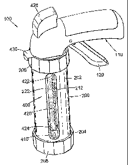
Referring initially to Figure 1 of the drawings, there is
shown a cookie dough dispenser in the form of a cookie gun
CA 02387687 2002-05-28 -7-
100 embodying the invention, which gun 100 comprises a
cylindrical barrel 200 for containing cookie dough and a
handle in the form of a pistol handgrip 300. The barrel
200 has upper and lower ends 202 and 204 that are closed
by respective plastics annular end caps 206 and 208. Each
end cap 206/208 is formed with internal screw-thread ribs
for releasably fastening onto the respective barrel end
202/204.
':'he lower end cap 208 serves to locate a disc-like die
(not shown) across the lower barrel end 204, which is
apertured and acts as an exit (or a nozzle) for cookie
dough in the barrel 200 to be dispensed. The apertures of
such dies are in different designs to determine the cross-
sectional shape of cookie dough dispensed and in turn the
outer shape of the cookies to be made.
The handgrip 300 incorporates a pull trigger 37.0 and is
integrally formed with the upper end cap 206 for in turn
releasable connection to the upper barrel end 202. The
pull trigger 310 is arranged to operate a cookie dough
dispensing mechanism 400 of the cookie gun 100, which is
provided within the barrel 200.
The cookie dough dispensing mechanism 400 is formed by a
piston 410 slidable along the axis of the barrel 200, a
shaft in the form of a ratchet rack 420 that extends co-
axially within the barrel 200 and carries or supports the
CA 02387687 2002-05-28
- S -
piston 410 for movement, a ratchet member in the form of a
pawl (not shown) repeatedly pivotable by the pull trigger
310 to advance the shaft 420 and hence the piston 410
stepwise downwards, and a spring-loaded tab 430 retaining
the shaft 420 against reverse movement. The piston 410
seals slidably with the inner surface of the barrel 200
and serves to press or squeeze, upon advance, cookie dough
in the barrel 200 out through the die at the barrel lower
end 204 onto a baking tray or the like for baking.
The ratchet rack 420 has upper and lower ends 422 and 424
and extends into the barrel 200 through the handgrip 300
and the upper end cap 206. The upper end 422 is fitted
with an external knob 426, by means of which the shaft 420
may be pulled back from within the barrel 200. The lower
end 424 supports the piston 410. Inside the handgrip 300,
the rack 420 is acted upon by the aforesaid pawl to
advance and is stopped by the tab 430 against moving back.
The tab 430 protrudes laterally out at a position between
the handgrip 300 and the upper end cap 206. When the tab
430 is manually pulled outwards, the ratchet rack 420 (and
the piston 410) is released and may then be pulled back by
the knob 426. Subsequently, the lower end cap 208 with the
die may be unscrewed to allow the barrel 200 to be
replenished with cookie dough.
Reference is now made to Figures 2 to 8. The barrel 200
CA 02387687 2002-05-28
-9-
consists of an outer cylinder 210 that is made of metal
preferably stainless steel, and an inner cylinder 220 that
is made of transparent or near-transparent plastics
material. The inner cylinder 220 is moulded co-axially
onto the inner surface of the outer cylinder 210 through
insert moulding operation. The outer cylinder 210 is
formed with a straight closed-ended slot 212 extending
longitudinally from adjacent one end 202/204 of the barrel
200 to near the other end 204/202.
Adjacent each end 202/204 of the barrel 200, the wall of
the outer cylinder 210 is deformed slightly outwards at
equiangular positions to form three protrusions in the
form of ribs 214. The ribs 214 are inclined at a small
angle to the cross-sectional plane of the cylinder 210 and
act as screw threads for fastening the respective end cap
206/208.
The inner cylinder 220 is moulded to cover substantially
the entire inner surface of the outer cylinder 210
including the slot 212, through which the wall of the
inner cylinder 220 is exposed to form a lens 222. The
position of the piston 410 and hence the amount of the
cookie dough remaining inside the barrel 200 can be
determined visually through the lens 222 as a window.
The lens 222 expands in thickness evenly outwards to
occupy substantially the entire volume of space defined by
CA 02387687 2002-05-28
-10-
the slot 212, such that the lens 222 lies flush with the
slot 212 on the outer surface of the outer cylinder 210.
This results in the outer surface of the barrel 200 across
the lens 222 being smooth. It is envisaged that the lens
222 may be moulded to be gradually relatively thicker
towards its central region to form a convex lens, such
that the piston 410 and/or the cookie dough inside the
barrel 200 can be seen more easily.
By reason of its formation through insert moulding, the
inner cylinder 220 is inherently attached and secured to
the outer cylinder 210, in ultimate surface contact
therewith, against the ingress of liquid through the
junction between the lens 222 and the slot 212 into the
interface between the two cylinders 210 and 220. The
engagement between the lens 222 and the slot 212
inherently prevents relative displacement between the two
cylinders 210 and 220. The ribs 214 form indentations on
the inner surface of the outer cylinder 210, with which
the material of the inner cylinder 220 moulded into shape
there engages, and this further reinforces the engagement
between the two cylinders 210 and 220 especially at the
upper and lower ends thereof.
Referring finally to Figures 9 to 13, there is shown an
alternative cylindrical barrel 300 that the cookie dough
dispenser 100 of Figure 1 may incorporate instead of the
aforesaid barrel 200. This barrel 300 consists of an outer
CA 02387687 2002-05-28
-11-
cylinder 310 that is made of metal preferably stainless
steel, and an inner cylinder 320 that is made of
transparent or near-transparent plastics rnaterial. The
inner cylinder 320 is moulded into shape independently and
then subsequently inserted co-axially into the outer
cylinder 310 as a sliding snug fit, in that the inner
cylinder 320 has an outer diameter marginally smaller than
the inner diameter of the outer cylinder 310 and their
lengths are substantially the same.
The outer cylinder 310 is formed with a straight slot 312
extending longitudinally from an upper end 302 of the
barrel 300 where the end of the slot 312 is open to near
the lower end 304 where the end of the slot 312 is closed.
Adjacent each end 302/304 of the barrel 300, the wall of
the outer cylinder 310 is deformed slightly outwards at
equiangular positions to form three protrusions in the
form of ribs 314. The ribs 314 are inclined at a small
angle to the cross-sectional plane of the cylinder 310 and
act as screw threads for fastening the respective end cap
206/208.
The inner cylinder 320 covers substantially the entire
inner surface of the outer cylinder 310 including the slot
312, through which the wall of the inner cylinder 320 is
thickened outwards to form a lens 322. The position of the
piston 410 and hence the amount of the cookie dough
n ~
CA 02387687 2002-05-28 _12_
remaining inside the barrel 300 can be determined visually
through the lens 322 as a window.
The lens 322 expands in thickness outwards to occupy the
entire volunie of space defined by the slot 312, in that
the outer surface of a short section 324 at the uppermost
end of the lens 322 lies flush with the outer surface of
the slot 312 to fit the upper end cap 206. Apart from this
short section 324, the lens 322 expands outwards beyond
the outer surface of the slot 312 and then laterally to
form a periphery that covers a substantial part of the rim
of the slot 312, except on opposite sides of the short
section 324. This results in a construction in that, apart
from the short section 324, the lens 322 along said
periphery embraces the rim of the slot 312 in a sliding
snug manner with a view to avoiding or minimising the
ingress of liquid through the junction between the lens
322 and the slot 312 into the interface between the two
cylinders 310 and 320.
The inner cylinder 320 is detachable from the outer
cylinder 310, or vice versa, such that in the case that
liquid does seep into the interface between the two
cylinders 310 and 320 during use, the cylinders 310 and
320 can be separated apart and washed independently.
It is envisaged that the lens 322 may be made gradually
relatively thicker towards its central region to form a
. ,: .. .~. .. . , .
CA 02387687 2002-05-28
- 13 -
convex lens, such that the piston 410 and/or the cookie
dough inside the barrel 300 can be seen more easily.
Turning back to the first barrel 200, it is clear that the
lens 222 may be moulded to have generally the same
structure as the second lens 322, i.e. expanding outwards
beyond the outer surface of the slot 212 and then
laterally to form a periphery that, in this case, covers
the entire rim of the slot 212. Such a slot 212 embraces
the rim of the slot 212 in a snug manner in order to avoid
or minimise the ingress of liquid through the junction
between the lens 222 and the slot 212 into the interface
between the two cylinders 210 and 220.
The barrel 200/300 of the subject invention is robust
because it is made of metal on the outside i.e. the
stainless steel outer cylinder 210/310, and is elegant in
appearance. The window, i.e. the slot 212/312 and lens
222/322, is inherently leak-proof because the lens 222/322
is an integral part of the plastics inner cylinder
220/320, which preferably forms the entire inner surface
of the barrel 200/300.
The invention has been given by way of example only, and
various other modifications of and/or alterations to the
described embodiments may be made by persons skilled in
the art without departing from the scope of the invention
as specified in the appended claims.