Note : Les descriptions sont présentées dans la langue officielle dans laquelle elles ont été soumises.
CA 02387848 2002-04-18
1
FILTERING UNIT FOR A VIRUCIDAL SUBSTANCE
The invention relates to a filtration unit intended to
remove a virucidal substance present in a biological fluid.
It typically applies to the case where the virucidal
substance has previously been added to a biological fluid,
in particular blood plasma, intended to be transfused into a
patient. The aim of this addition is to subject the
biological fluid to a viral inactivation treatment prior to
its transfusion into the patient, so as to inactivate any
viruses infecting the biological fluid.
A conventional technique for viral inactivation of plasma
uses a colouring substance as a virucidal substance, for
example methylene blue or one of its derivatives.
The principle of this technique is based on photochemical
reactions between the colouring substance and the viral DNA
or RNA which may be present in the biological fluid.
CA 02387848 2002-04-18
2
Exposure of the colouring substance to light brings about a
photochemical reaction which transmits energy to the DNA and
RNA molecules so that the virus is inactivated.
During these photochemical reactions, the colouring
substance is not removed so that it remains in the
biological fluid after exposure to light.
After the use of this viral inactivation technique, a very
small amount of the colouring substance may be left in the
biological fluid and thus be transfused into the patient at
the same time as the biological fluid.
However, recent studies seem to show the possible toxicity
of certain colouring substances used, and in particular
methylene blue, when they are injected into the patient.
So much so that many countries are demanding the systematic
removal of colouring substances prior to injection of the
biological fluid into the patient.
The invention therefore aims to propose a filtration unit
which makes it possible to remove substantially all the
virucidal substance present in the biological fluid while
leaving the composition of the biological fluid
substantially unchanged during the filtration.
To that end, the object of the invention is a filtration
unit intended to remove a virucidal substance present in a
biological fluid, comprising an outer casing provided with
at least one input aperture and at least one output
aperture, the casing containing a filter medium which
delimits two compartments, respectively input and output, of
the filtration unit, in which the filter medium is produced
from at least one hydrophilic material in the form of a
porous non-woven material and/or a porous membrane capable
of absorbing and/or adsorbing the virucidal substance.
CA 02387848 2002-04-18
3
According to one embodiment, the mean porosity of the filter
medium is defined so that the contact area between the
biological fluid and the filter medium is sufficient to
remove substantially all the virucidal substance while
leaving the composition of the biological fluid
substantially unchanged during its passage through the
filter medium, namely being between 1 m and 15 m.
In a variant, the mean diameter of the fibres of the porous
non-woven material is between 0.5 m and 5 m.
The input compartment and/or the output compartment
communicate with the outside of the filtration unit by means
of an input, respectively output, tube.
The hydrophilic material of the filter medium is chosen in
particular from amongst the naturally hydrophilic materials
or the materials, in particular based on plastic material,
made hydrophilic, for example from amongst the polymers
and/or the copolymers based on polyester, acrylonitrile or
polyvinylidene fluoride.
According to one embodiment, the filter medium comprises a
number of layers of hydrophilic material, identical or
different in nature to one another, with a contact area
identical or different to one another.
The filter medium has for example a thickness between 1 and
10 millimetres.
According to one embodiment, the outer casing of the
filtration unit is rigid.
According to another embodiment, the outer casing of the
filtration unit is flexible.
CA 02387848 2002-04-18
4
In a variant, the flexible casing is formed from two sheets
of flexible plastic material connected together on their
periphery, the filter medium being held in a flexible and
impervious frame delimiting, with the filter medium, the
input and output compartments of the filtration unit.
The flexible frame is, for example, formed from two flexible
sheets perforated between them between which the filter
medium is placed, the flexible sheets being fixed to one
another in the region of the periphery of the filter medium
and also with the sheets forming the outer casing, in the
region of the periphery of the outer casing of the
filtration unit.
The fixing of the sheets forming the flexible frame is then
a weld seam made through the filter medium.
According to one embodiment, the output compartment is kept
clear of the filter medium by the presence of one or more
spacing rods disposed between the filter medium and the
flexible outer casing, inside the output compartment.
The spacing rod or rods are produced from flexible tubes
welded for example at the inner wall of the sheet of the
outer casing.
Other objects and advantages of the invention will emerge
during the description which follows with reference to the
accompanying drawings.
Figure 1 depicts, in side view and longitudinal section, one
embodiment of the filtration unit comprising a flexible
outer casing.
Figure 2 depicts, in front view and partial longitudinal
section, the embodiment of Figure 1 showing in particular
the assembly of the filter medium in a flexible frame.
CA 02387848 2002-04-18
Figure 3 depicts, in top view and transverse section, the
embodiment of Figure 1, showing in particular the assembly
of the frame containing the filter medium in the outer
casing.
5 Figure 4 depicts, in front view and partial longitudinal
section, the filtration unit of Figure 3 in which the
spacing rods appear.
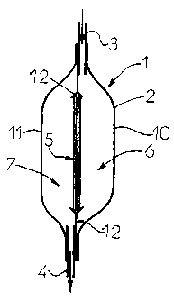
A filtration unit 1 intended to remove a virucidal substance
present in a biological fluid comprises typically an outer
casing 2 provided with at least one input aperture 3 and at
least one output aperture 4, the casing containing a filter
medium 5 which delimits two compartments, respectively input
6 and output 7, of the filtration unit 1.
In the description, the words "input" and "output" are
defined with respect to the direction of movement of the
biological fluid in the filtration unit 1 (see the arrows
shown in Figure 1).
According to one particular embodiment, the biological fluid
is blood or a blood compound, in particular blood plasma,
and the virucidal substance is methylene blue or one of its
derivatives.
Prior to its passage into the filtration unit 1, the
biological fluid has undergone a viral inactivation
treatment by means of the virucidal substance which was
added to the biological fluid.
This treatment, generally used at the blood transfusion
centre, will not be described further here.
The filtration unit 1 is intended to be integrated, in
particular by means of tubes, respectively input 8 and
output 9, into a system comprising for example bags for
CA 02387848 2002-04-18
6
medical use, tubes, clamps or other filters (for example to
remove leukocytes from the biological fluid).
In such a system, the filtration unit 1 is disposed on the
flow path of the biological fluid so that the biological
fluid with the virucidal substance added enters the
filtration unit 1 by the input aperture 3 and the biological
fluid free from the virucidal substance is delivered by
means of the output aperture 4.
One particular example of such a system is a transfusion
line of a bag containing a biological fluid to be transfused
into a patient. In such a line, the filtration unit 1 is
connected by its input 3 to the bag containing the
biological fluid with the virucidal substance added and by
its output 4 to means of transfusion of the biological fluid
free from virucidal substance.
These various systems are not described further inasmuch as
they comprise the filtration unit 1 according to the
structure described here.
A description is now given of a first embodiment of the
filtration unit 1 comprising a flexible outer casing 2
formed by the assembly of two sheets of flexible plastic
material 10, 11 connected to one another, for example by
welding, on their periphery (Figure 1).
This outer casing contains a filter medium designated
generally by the reference 5, the structure of which will be
described in more detail below.
The filter medium 5 is held in a flexible and impervious
support frame 12 and delimits two compartments, respectively
input 6 and output 7, of the filtration unit 1.
CA 02387848 2002-04-18
7
The input compartment 6 communicates with the outside of the
filtration unit 1 by means of an input tube 8 which is used
to fill it with the biological fluid with the virucidal
substance added.
The output compartment 7 communicates with the outside of
the filtration unit 1 by means of an output tube 9 which
delivers the biological fluid free from virucidal substance.
The structure of the filtration unit 1 thus allows the
biological fluid with the virucidal substance added to be
received in the input compartment 6 via the input aperture
3, to pass through the filter medium 5 so that the virucidal
substance is absorbed and/or adsorbed thereby, and then the
biological fluid free from virucidal substance is received
in the output compartment 7 in order to be delivered via the
output aperture 4.
According to one embodiment, the input tubes 8 and/or output
tubes 9 are flexible, and can be cut and welded.
Where a collecting bag is associated with the output tube 9,
this embodiment makes it possible, after separation of the
filtration unit 1 by cutting and welding of the output tube
9, to obtain a bag full of biological fluid free from
virucidal substance. Such a bag can then be used
conventionally, for example for transfusion into a patient.
A first level of sealing of the filtration unit 1 is
provided between the filter medium 5 and the flexible frame
12 where no tube passes.
A second level of sealing is provided at the periphery of
the filtration unit 1 where the two outer sheets 10,11, the
periphery of the flexible frame 12 and the passage of the
input tube 8 and output tube 9 come together.
CA 02387848 2002-04-18
8
This second level of sealing can be provided by the known
techniques for connecting plastic materials, for example by
high-frequency welding.
The implementation of the assembly of the filtration unit 1
is now described with reference to Figures 2 to 4.
The flexible frame 12 is formed by an assembly of two sheets
13, 14, for example plasticised sheets, between which the
filter medium 5 is placed.
These two sheets 13, 14 are perforated in their central part
and each have at least one opening 15, 16 allowing passage
of the biological fluid to be filtered.
The two sheets 13, 14 are fixed to one another preferably in
the region of the periphery of the filter medium 5, for
example by a weld seam 17, made through the filter medium 5,
providing both the fixing of the filter medium 5 and also
the sealing of the unit 1.
The welding of the sheets 13, 14 through the filter medium 5
causes a compression 18, forming an impervious seam around
the filter medium S.
The periphery 19 of the flexible frame 12 is also welded
with the outer sheets 10, 11 forming the outer casing 2 of
the filtration unit 1, these being welded to one another
over their entire circumference and in the region of their
periphery, thus providing the sealing of the unit 1.
In order to avoid the filter medium 5 sticking against the
outer casing 2, and thus interfering with the flow of the
biological fluid into the output compartment 7, two spacing
rods 20, 21 are placed inside the output compartment 7,
between the filter medium 5 and the outer casing 2.
CA 02387848 2002-04-18
9
These two rods 20, 21 keep the output compartment 7 clear of
the filter medium 5 and thus avoid the filter medium 5 being
flattened against the inner wall of the outer sheet 2.
The rods 20, 21 can be produced from flexible tubes welded
for example at the inner wall of the sheet of the outer
casing 2, for example in the region of the peripheral weld
19 of the filtration unit 1.
It is self-evident that the number of spacing rods can vary,
depending for example on the dimensions of the filtration
unit 1.
For example, provision of a single spacing rod folded so as
to form a loop inside the output compartment 7 can be
envisaged.
Preferably, flexible rods are used, in order not to
interfere with the possibilities of folding the filtration
unit 1.
In a second embodiment (not depicted), the filtration unit 1
comprises a rigid outer casing 2, for example made of a
rigid plastic material such as polycarbonate.
There will now be described in more detail the structure and
implementation of the filter medium 5 capable of removing
substantially all the virucidal substance while leaving the
composition of the biological fluid substantially unchanged
during the filtration.
In a first embodiment, the filter medium 5 is produced from
at least one hydrophilic material in the form of a porous
non-woven material.
CA 02387848 2002-04-18
In a second embodiment, the filter medium 5 is produced from
at least one hydrophilic material in the form of a porous
membrane.
In a third embodiment, the filter medium 5 is produced from
5 a hydrophilic material in the form of at least one porous
membrane which is inserted between a number of layers of
hydrophilic material in the form of a non-woven material.
In these three embodiments, the hydrophilic material is
capable of absorbing and/or adsorbing the virucidal
10 substance, in particular by affinity between the virucidal
substance and the hydrophilic material.
Various materials can be used for producing the filter
medium depending on the nature of the fluid to be filtered
and that of the biological fluid.
The choice of materials usable in the filtration unit
according to the invention is however limited by the fact
that they must not prevent, in particular by affinity, the
passage of the cellular or non-cellular constituents of the
biological fluid.
In other words, the material forming the filter medium must
be capable of absorbing and/or adsorbing the virucidal
substance but not the constituents of the biological fluid.
In the case of treatment of a blood plasma containing
methylene blue, the following can be cited amongst the
possible materials: the polymers and/or the copolymers based
on polyester, acrylonitrile or polyvinylidene fluoride.
These polymeric products are generally not naturally
hydrophilic and must be treated by physical and/or chemical
methods, in order to give them said hydrophilic properties.
CA 02387848 2002-04-18
11
These treatments consist for example in grafting hydrophilic
substituents, for example hydroxyl or carboxylic type
groups, onto the polymer, according to known methods.
Such polymers made hydrophilic by physical and/or chemical
treatment are available on the market.
The hydrophilic nature of the material forming the filter
medium 5 allows a good wettability of the filter medium
during passage of the biological fluid, which allows in
particular a better flow of the biological fluid through the
filtration unit 1 but also an improvement in the filtration
efficiency.
The porosity characteristics of the filter medium allow the
passage of the biological fluid through the filtration unit
while leaving the composition of the biological fluid
substantially unchanged.
To that end, the mean size of the pores of the filter medium
is chosen according to the biological fluid to be treated.
For example, for the filtration unit 1 to allow the
constituents of whole blood to pass, the mean size of the
pores can be of the order of or greater than 7 m. In the
case of blood plasma, the mean size of the pores can be
smaller, for example of the order of 4 m, on account of the
absence of cellular constituents in the plasma.
During passage of the biological fluid with the virucidal
substance added through the filter medium 5, the contact
area between the biological fluid and the filter medium must
be sufficient to remove substantially all the virucidal
substance while leaving the composition of the biological
fluid substantially unchanged.
CA 02387848 2002-04-18
12
In the first embodiment, this characteristic is
advantageously obtained by means of the use of a non-woven
material which has, through its structure, a large contact
area for a small volume.
Contact area between the biological fluid and the filter
medium means the area over which the absorption and/or
adsorption of the virucidal substance by the porous material
can take place. It is self-evident that this area is a
function in particular of the area of the filter medium, its
porosity, its thickness and the diameter of the fibres of
the non-woven material.
Thus, by changing the diameter of the fibres, the porosity
of the non-woven material and the thickness of the filter
medium 5 it composes, access can be obtained to a wide range
of contact areas which makes it possible to remove
substantially all the virucidal substance while leaving the
composition of the biological fluid substantially unchanged.
By way of example, there can be cited a filter medium 5
formed from a non-woven material made of polyester having a
thickness of the order of 5 mm, a mean porosity of the order
of 8 m and a mean fibre diameter of the order of 2 m,
allowing the removal of a concentration of 1 M of methylene
blue in 250 ml of blood plasma.
It should be noted however that these values can vary to a
great extent, in particular according to the time of contact
between the filter medium and the biological fluid, that is
to say the filtration speed.
In the second embodiment, a porous membrane is used as the
filter medium 5 to absorb and/or adsorb the virucidal
substance present in the biological fluid.
CA 02387848 2002-04-18
13
In one particular example, such a membrane is made of
polyvinylidene fluoride and with a pore size calibrated to a
value between 1 and 15 m.
In the third embodiment, the filter medium 5 can combine the
two materials used in the preceding embodiments, namely
comprise a number of layers of hydrophilic material in the
form of a porous non-woven material and one or more porous
membranes. The material and/or the structure of the
material forming these layers can then be identical or
different to one another.
The layers are then disposed, for example contiguously, next
to one another in the filtration unit so that the biological
fluid passes through them successively during the
filtration.
In one particular example, there can be cited a filter
medium 5 formed from a superposition of layers formed
respectively of a "spunbond" type polyester non-woven
material, a "meltblown" type polyester non-woven material,
one or more polyvinylidene fluoride membranes, a"meltblown"
type polyester non-woven material and a "spunbond" type
polyester non-woven material.
The words "spunbond" and "meltblown" mean two of the
conventional methods of forming a layer of non-woven
material directly from the polymer, namely respectively
either by forming continuous monofilaments or by blowing the
polymer in the molten state into irregular filaments.
As these techniques are conventional, they will not be
detailed further here.
In this embodiment, the two outer layers of "spunbond" non-
woven material are identical and serve respectively as a
pre- and post-filter. Furthermore, they have the function
CA 02387848 2002-04-18
14
of improving the weldability of the filter medium 5 onto the
casing 2 of the filtration unit 1.
The two layers of "meltblown" non-woven material and the
membrane or membranes placed between them form more
particularly the filter medium 5 capable of absorbing and/or
adsorbing the virucidal substance.
Furthermore, the two layers of "meltblown" non-woven
material are identical and have the function of protecting
the membrane or membranes.