Note : Les descriptions sont présentées dans la langue officielle dans laquelle elles ont été soumises.
CA 02388707 2002-04-18
WO 01/31367 PCT/US00/28804
1
METHOD FOR MAKING NANOCRYSTALLINE GLASS-CERAMIC FIBERS
CLAIM OF PRIORITY
The present application claims the benefit of United States Provisional
Application Serial No. 60/160,052, entitled NANOCRYSTALLINE GLASS-
CERAMIC FIBERS AND METHOD OF MAKING THEM, filed on October 18,
1999 in the names of George H. Beall, Linda R. Pinckney, William Vockroth and
Ji
Wang.
FIELD OF THE INVENTION
A method for making glass ceramic, optoelectronic materials that contain
nanocrystals that are doped with at least one kind of optically active metal.
BACKGROUND OF THE INVENTION
Over the past few decades, fiber optic systems have become the standard for
long-distance communication. This preponderance stems from several advantages
of
optical links over the more traditional metallic-based counterparts, including
lower
loss, higher information capacity, low cost per channel, immunity to crosstalk
and
electrical interference, and a smaller physical mass. Currently, optical fiber
systems
2 0 carry hundreds of terabits per second over distances greater than 1000 km.
Even
though the capacity of optical fibers is orders of magnitude beyond the
capability of
metallic links, the demands of global communication are driving the system
capacity
to double every year.
CA 02388707 2002-04-18
WO 01/31367 PCT/US00/28804
-2-
Transition metals have long been used as optically active dopants in
crystalline hosts because they fluoresce in the near infrared (1000 - 1500 nm)
region,
while exhibiting a correspondingly large bandwidth. For example, disclosed in
U.S.
Patent No. 4,987,575 to Alfano et al. are Cr4+ doped crystals that are capable
of lasing
near 1.3 qm. Another example is titanium-doped sapphire (Ti : A12 03), which
provides optical gain in the range of about 650-1100 nm.
Given the useful wavelength range and bandwidth of many transition metal
dopants, one can see that their advantageous attributes could be put to good
use in
telecommunications applications. The crystalline-host transition metal
technology of
Patent No. 4,987,575, however, is not suited for these applications, since the
primary
optical communications medium is glass-based optical fiber. While a logical
extension would be the inclusion of transition metal dopants into glasses,
their
performance (particularly their efficiency) has unfortunately been found to
degrade in
amorphous hosts, where the crystal field strength is much smaller than single-
crystal
hosts. The transition metal ions instead, merely are suspended in the
amorphous body
providing or contributing little to the amplification or transmission
qualities.
Another approach has been considered by Alfano et al. in U.S. Patent No.
5,717,517, whereby the laser-active Cr+4 (or V+3)-doped crystal is
manufactured as a
2 0 plurality of particles, to be dispersed in a "non-gaseous" medium. In this
manner, the
dopants remain laser-active within a crystalline host while the larger,
surrounding
medium is compatible with fiber optic technology. In order to minimize the
optical
losses from such a composite medium, both the particles and their index
difference
from the surrounding medium must be small. These requirements were recognized
in
2 5 the patent by Alfano et al., and the particle size was therefore
stipulated to be between
0.05 and 500 Vim, while the index mismatch was specified to be lower than 0.1.
While the concept of dispersing crystalline particles in an amorphous medium
is valid, this technology has several severe drawbacks, primary of which is
the
manufacture of the microscopic particles and their uniform distribution in a
suitable
3 0 matrix. Certainly the loss decreases with particle size, and the smallest
particles (0.05
~,m) are therefore desirable. Grinding of material generally has difficulty
producing
particles smaller than 1 qm however, and even the sol-gel method of producing
CA 02388707 2002-04-18
WO 01/31367 PCT/US00/28804
-3-
forsterite has trouble attaining particles smaller than this size. While some
techniques
have attained particles on the 0.5 p,m scale, another order of magnitude
smaller seems
difficult to achieve. Even allowing for the smallest particle size of 0.05
p,m, a simple
analysis of the scattering losses reveals another major shortcoming of this
technique.
To overcome the shortening of the aforementioned materials and techniques,
we describe a method for making glass-ceramic optical fibers. Glass ceramics
have
the advantage described in a United States patent application entitled
TRANSITION-
METAL GLASS-CERAMIC GAIN MEDIA, filed in the name of George H. Beall,
Nicholas F. Borrelli, Linda R. Pinckney, Eric J. Mozdy, on October 11, 2000,
which
is incorporated by reference in its entirety, herein. The process of internal
nucleation
forms a glass ceramic, where the crystalline sites are small and uniformly
distributed
throughout the glass core. The crystals are formed from constituent materials
of the
original glass melt, not by introducing new materials as disclosed in U.S.
Patent No.
5,717,517. Moreover, the optically active dopants are introduced throughout
the
entire medium, as compared to only scattered particles.
When making an optical fiber from glass ceramic materials, the nature of a
glass-ceramic material generally necessitates drawing the material as a glass
fiber and
subsequently subjecting the fiber to an appropriate thermal treatment to
develop the
crystalline phase. Most glass-ceramic fibers, currently known, are made by
using a
2 0 "double-crucible method". Accordingly, it has become customary to employ
an
apparatus known as a double crucible in drawing glasses to be converted to a
glass-
ceramic. The double crucible embodies a central tube for the core glass of a
fiber. A
larger diameter tube, surrounding the central tube, delivers the cladding
glass. The
respective glasses are maintained in a molten state in their crucibles, and
flow from
2 5 the tubular outlets to be drawn as a clad fiber.
In drawing optical fibers from glass-ceramic compositions, the most critical
issue of concern is how to suppress the intense tendency of the compositions
to
crystallize as the glass is processed when attempting to form a glassy fiber.
This
phenomenon is due to the fact that the compositions for the precursor glass
for a
3 0 glass-ceramic, particularly the high temperature glass-ceramics useful for
present
purposes, are purposely designed to crystallize. Accordingly, in drawing a
clad glass
CA 02388707 2002-04-18
WO 01/31367 PCT/US00/28804
-4-
for present purposes, a critical problem is how to suppress this intense
tendency to
crystallize, thereby maintaining the fiber as a glass.
We have found various drawbacks in using the double crucible method. But
the major shortcoming of this approach that the present invention is directed
to
ameliorate is the propensity of the respective glass components to undergo
strong
chemical inter-diffusion and/or interaction between the core material and the
cladding
material, because both glasses are in a fairly fluid or liquid state. Both the
core and
clad composition typically contain siginificant amounts of monovalent and
divalent
ions, which are likely to migrate across the core-clad interface. Diffusion
problems
may seriously alter the composition of the core glass-ceramic, and even render
it
incapable of being cerammed in a subsequent thermal treatment.
Hence, a problem exists that the present invention is directed to solving. The
invention provides a method to minimize cross-diffusion between the core and
cladding materials during the optical fiber manufacturing process. The method
described in this application is a very different method of fiberizing a glass-
ceramic
material, which offers certain advantages particularly with respect to the
cladding,
described below, and is the preferred fiberization method for certain glass
ceramic
compositions.
2 0 SUMMARY OF THE INVENTION
The present invention resides in a method to produce clad optical fiber and
other materials for optoelectronic applications, including lasers and
amplifiers,
without having to suffer unnecessarily, when forming and drawing optical
fiber,
contamination of the fiber core by the cladding material. More particularly,
the
2 5 invention provides a unique method for making an optoelectronic material
by
modifying the "rod-in-tube" process to produce a clad optical fiber. Diffusion
of
contaminant elements into the precursor glass compositions for the glass-
ceramic
fiber core is kept to a minimum. Maintaining the purity of the core and its
transparency to light is useful and favored in optoelectronic applications.
The method
3 0 can best be described as a "viscous-liquid-in-tube" process, wherein
precursor glass
compositions for making glass-ceramic materials that contain nanocrystals
doped with
optically active ions are employed with a more refractory or temperature
resistant
CA 02388707 2002-04-18
WO 01/31367 PCT/US00/28804
-5-
cladding material. According to the inventive method, a precursor glass
composition
is first prepared and formed into a cane. Second, a chemically inert cladding
material
comprising, for example, modified silica is formed into a tube that is fitted
around the
glass cane. Third, a glass fiber is drawn from the combined precursor-glass-
cane-in-
tube at a temperature slightly above the liquidus of the fiber-core glass
composition,
and subsequently at least a portion of the drawn clad glass fiber is heat
treated to
develop nanocrystals within the core composition, thereby forming a glass
ceramic.
BRIEF DESCRIPTION OF THE DRAWINGS
Figure 1 A. A differential thermal analysis (DTA) curve showing temperature
ranges
used for current Rod-in-Tube (RIT) and Double-Crucible (DC) fiber-drawing
processes, respectively.
Figure 1 B. Differential thermal analysis (DTA) curves indicating the
respective areas
of formative regions of glass-ceramic fiber fiberization used in creating the
present
invention, a "viscous" liquid-in-tube process.
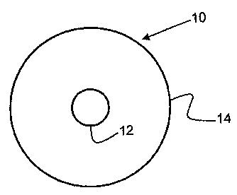
Figure 2. A cross-sectional view of a clad optical fiber in accordance with
the present
invention.
DESCRIPTION OF THE INVENTION
2 0 The previous method of drawing optical fibers from most glass-ceramic
compositions, as mentioned before, involved using a double-crucible. This
method
tends to exacerbate contamination of the precursor glass composition used in
the fiber
core by the cladding material. Contamination would substantially alter the
composition of the later formed glass-ceramic material of the core. In the
present
2 5 invention, we propose an original method to produce clad optical fiber and
other
optoelectronic devices used in telecommunications. The invention is described
with
reference to a clad optical fiber as a component in optoelectronic devices
such as
lasers and amplifiers where it presently finds application. However, it is not
necessarily so limited, and those skilled in the art of clad materials will no
doubt
3 0 readily see other applications.
The invention involves using the thermal properties of materials in a way to
produce transparent glass-ceramic fiber cores in combination with a durable
cladding.
CA 02388707 2002-04-18
WO 01/31367 PCT/iJS00/28804
-6-
Figures 1 A and 1 B illustrate the thermodynamic principles involved in the
invention.
In contrast to currently employed "rod-in-tube" draw processes that operate in
a lower
temperature range, between the glass transition temperature (T~ and
crystallization
temperature (TX) as shown in Figure 1A, the present inventive process occurs
at a
higher temperature. At temperatures lower than those used in the present
invention,
the glass composition of the core tends to devitrify, often forming crystals
too large to
permit effective light transmission. It is, therefore, desirable to avoid any
uncontrolled crystallization in the glass fiber as it is being drawn and clad.
Crystal
formation at an early stage of manufacture is inopportune and can cause many
complications latter on. The glass composition of the core should remain
glassy at
this stage of production. As can be seen in Figure 1B, to completely avoid
crystallization of the glass-ceramic composition when making a preform draw,
the
draw should be carned-out at a temperature just above the liquidus temperature
(Ti) of
the candidate glass-ceramic material that will be used as the core of a fiber.
At the
other temperature extreme, suitable for current double crucible processes, the
outer
cladding material may become too soft and compositional species may become
mobile. Thus, as described before, too much chemical reaction occurs between
the
core and clad compositions. A material for cladding that can withstand higher
temperatures and that is unlikely to chemically react or diffuse with the core
glass
2 0 composition is used to surround the fiber core before drawing begins.
Thus, the new
method entails essentially a shifting of the respective temperature dynamics
for the
core and cladding materials. In other words, even though both materials are
subjected
to the same temperature during the draw process, the temperature is slightly
above the
liquidus temperature (T~) of the glass in the core, while simultaneously
remaining
2 5 below the kinetically-controlled crystallization temperature (TX) of the
much more
viscous cladding glass. This process can also be described as a conceptual
hybrid
between the rod-in-tube and the double crucible methods.
Figure 2 is a cross-sectional view of a clad fiber in accordance with the
present
invention. In the Figure, a clad fiber is designated by the numeral 10. Clad
fiber 10
3 0 comprises a core fiber 12 having a cladding layer 14 deposited on the
surface of fiber
12 and encasing it. Dimensions are considerably exaggerated in the interest of
clarity.
CA 02388707 2002-04-18
WO 01/31367 PCT/US00/28804
The fiber core 12 is made from a high temperature glass-ceramic material
having a liquidus-viscosity in the range of approximately from 100-200-2500
poises.
Although the viscosity of the glass core composition at liquidus temperature
may be
low by conventional glass standards, the core material nevertheless has a
sufficiently
high viscosity at the liquidus temperature to minimize diffusion of component
elements. Glass ceramic compositions that can work well with the inventive
method
of making fiber typically have a softening point above about 900° C.
Specific
examples of these kinds of glass compositions include a substantially
transparent,
alpha- and beta-willemite glass-ceramic, which may be doped with transition-
metals
to impart optical activity, as disclosed in a United States patent application
entitled
GLASS-CERAMICS BASED ON ALPHA- AND BETA-WILLEMITE, filed in the
name of Linda R. Pinckney, and assigned to the same assignee as this
application; or,
transition-metal-doped, glass-ceramic materials that exhibit properties that
make them
suitable as gain media in optical amplifiers and/or laser pumps, as described
in a
United States patent application entitled TRANSPARENT (LITHIUM, ZINC,
MAGNESIUM) ORTHOSILICATE GLASS-CERAMICS, filed in the names of
George H. Beall and Linda R. Pinckney, and also assigned to the same assignee
as
this application. Both of these patent applications were filed on October 1 l,
2000,
and are incorporated by reference herein in their entirety. These glass
ceramic
2 0 compositions are characterized in that the defining crystal phases) is
nanocrystalline
in nature, that is, the crystals can range from being not larger than about SO
nm in
diameter, to 25 nm to, 10 nm or even as small as 5 nm. Further, these
compositions
are doped with at least one kind of optically active ion. Optically active
ions for
example may be chosen from either the transition metals or the lanthanide
elements.
2 5 Transition-metal doped nanocrystalline glass-ceramics are a unique class
of
novel laser and optical amplifying material used for optoelectronic
applications.
More particularly, applicable transition metal dopants can include titanium
(Ti),
vanadium (V), chromium (Cr), manganese (Mn), cobalt (Co), nickel (Ni), copper
(Cu), or even iron (Fe). Glass ceramic materials doped with transition metal
ions
3 0 preserve not only their typical broad-emission characteristics, but also
tend to show
high, crystal-like quantum yield as compared to similarly-doped amorphous,
pure
glass hosts. Thus, they provide the advantages of a pure crystal in terms of
CA 02388707 2002-04-18
WO 01/31367 PCT/US00/28804
_g_
spectroscopic characteristics. At the same time, they provide the advantages
of a
glass insofar as material processing is concerned. A similar effect is noticed
when
lanthanide elements, for example, erbium (Er), thulium (Tm), neodymium (Nd),
praseodymium (Pr), or ytterbium (Yb), dysprosium (Dy), holmium (Ho) are doped
into the glass-ceramic.
In some cases, a small amount of alkali or halogen ions in the core material
may be lost and this may be easily compensated by adding a little extra amount
of the
volatile components in the starting batches of the core glass composition.
A common practice in optical fiber production is to apply a cladding layer to
the optical fiber core. This cladding layer surrounds the fiber as shown by
cladding
layer 14 in Figure 2. This cladding layer serves to maintain an optical signal
within
the fiber core, since it is lower in refractive index than the core. To avoid
stress and
potential cracking, however, the cladding should provide a close match in
coefficient
of thermal expansion (CTE) with the core. Preferably, the CTE of the cladding
will
be slightly lower than that of the core to thereby induce a small compressive
stress
and lend a source of mechanical strength.
The question then becomes what guidelines dictate the cladding material to be
chosen for use in our invention. We believe that our invention satisfies the
following
two concerns when choosing a suitable cladding material for optical fiber.
First, and
foremost, the cladding material should exhibit relatively high viscosity and
the
absence of significant amounts of mobile species R+, Rz+ in the cladding, so
as to
minimize diffusion rates of the elements in the core material. This
characteristic
reduces the amount of cross diffusion between the core and cladding materials.
Yet,
the cladding should be soft enough and drawable before the core material
becomes
too molten, soft, or volatile. In other words, the cladding must be
sufficiently viscous
at the drawing temperature to permit it to be drawn, while the core glass
should
remain compositionally stable, that is, have a sufficiently low vapor pressure
to avoid
appreciable volatility. According to the inventive method, the ratio of the
viscosity of
the cladding to the viscosity of the core is about three orders of magnitude,
(cladding:core ~ 106:103), so as to minimize diffusion.
The liquid core material should remain as a viscous liquid, having as low a
vapor pressure as possible. Second, at the same time, the cladding should be
CA 02388707 2002-04-18
WO 01/31367 PCT/US00/28804
-9-
chemically inert with respect to the glass of the core. That is, the cladding
material
reacts only minimally, if at all, with the viscous-liquid core.
A cladding material that satisfies these two concerns can comprise a
composition of predominantly silica modified with additives. Suitable
additives for
modifying silica include oxides of boron (B), germanium (Ge), phosphorous (P),
aluminum (Al), gallium (Ga), tantalum (Ta), titanium (Ti) and antimony (Sb).
These
oxide additives are oxides known as conditional glass-forming oxides with
silica, and
any one of which may be used singly or in combination with another.
Silica materials modified with these elements, but particularly B, Ge, and/or
P,
exhibit several relevant characteristics. First, no-bridging oxygen exists in
these
cladding materials and all bonds are fully saturated, thus these materials
exhibit strong
chemically inert properties. The B, Ge and P oxides are preferred, with the B
and Ge
being slightly favored. Phosphorous is more effective in decreasing the
softening
point, but its double bond may leave bigger voids in the glass structure.
These voids
may permit entry of alkali ions, thereby lessening the chemically inert
properties of
the cladding. In general, alkali metal and alkaline earth metal oxides are
avoided to
the extent feasible. These compounds tend to reduce chemical inertness and
tend to
unduly lower the glass softening point.
Second, by avoiding alkali and alkaline earth metal oxides, the softening
points of these materials can be varied greatly ranging from about 1200
°C to as high
as that of pure silica, depending on the requirements of the compositional
nature of
the core material. A high softening temperature provides, according to an
embodiment of the inventive method, a drawing temperature that is slightly
above the
liquidus temperature of the core composition. Third, high temperature glass-
ceramics
may have coefficients of thermal expansion in the range of about 10-
90x10''/°C, but
more often within the range of 20-70x10''/°C, or 30-60x10'7/°C.
The cladding
material used will then preferably have a somewhat lower CTE than that of the
core
glass. For example, the cladding then can have a CTE in the range of about 5-
70x10'
'/°C, or in the range of 15-60x10''/°C but more likely within 15-
25x10'/°C. As
stated before, the differential between coefficients of thermal expansion
provides
compressive stress that helps strengthen the clad fiber.
CA 02388707 2002-04-18
WO 01/31367 PCT/US00/28804
-10-
One other favorable feature of the inventive method is the fiber produced is
compatible with silica-based fiber technology and is easily fusion spliced,
since the
cladding contains high amounts of silica.
In other methods such as cutlet-in-tube, when substantial time is required to
heat and melt the cutlet, a great amount of diffusion can occur with the
cladding.
Since the core material employed in the inventive method is already a nicely
formed
glass material, the tendency for diffusion of component elements is reduced.
Having discussed the nature of the nanocrystalline, glass-ceramic core, and
modified-silica cladding materials, it is easier to understand our new method
for
fiberization. The method is similar to a "rod-in-tube" approach, yet
substantially
different because the inventive method makes better use of the thermal
properties of
these materials. As touched upon before, it is clear that fiber drawing
according to
our invention should generally be carned out at a temperature just above the
liquidus
temperature of the glass fiber core. This is not to disavow that if the
kinetics of
crystallization are sufficiently slow, however, the fiber can be drawn at a
temperature
below the liquidus temperature of the core glass. Additionally, the more
refractive
nature of the modified silica cladding can withstand much higher temperatures
than
previous cladding materials used in the conventional rod-in-tube approach. In
our
inventive method, a clad glass fiber is first produced by drawing a cane from
the
2 0 precursor glass and cladding it with a cladding of modified silica, as
described above.
The modified silica tube is preferably fabricated by an outside chemical vapor
deposition (CVD) process such as OVD or VAD, but traditional fusion or flame
process may be employed as well. CVD produced modified silica cladding tends
not
to contain monovalent or divalent ions. Cladding may be attached to the core
in a
2 5 mechanical process by placing the core within the cladding. As shown in
Figure 1 B,
the drawing process occurs at a temperature that is above liquidus for the
core, and
below crystallization for the cladding. The clad glass fiber is drawn and then
subjected to an appropriate thermal treatment to crystallize either during the
drawing
process or, more commonly, in a subsequent step.
3 0 Thus to recapitulate, our invention is. in part a method for making an
optoelectronic material. The method comprises several steps: a) preparing a
glass
composition to yield a precursor glass for a nanocrystalline glass ceramic
doped with
CA 02388707 2002-04-18
WO 01/31367 PCT/US00/28804
-11-
at least one kind of optically active ion; b) forming the precursor glass into
a glass
cane; c) incorporating the glass cane with a chemically inert cladding
material,
preferably made from modified silica; d) making an optical component, such as
a
fiber, from the combined glass cane and cladding at a temperature slightly
above the
liquidus temperature of the relatively more fluid, precursor glass, and below
the
kinetic crystallization temperature of the viscous cladding (glass) material;
e) heat
treating at least a portion of the optical component to develop nanocrystals
within the
precursor glass. The optically active dopant is selected from transition
metals and
lanthanides. The nanocrystals formed in the glass ceramic are not larger than
about
50 nm, and may be as small as 5 nm, in size.
In the making of a glass optical fiber according to the inventive method, the
cladding glass is sufficiently viscous at the drawing temperature to permit it
to be
drawn at a temperature where the core glass is chemically stable even though
more
fluid than the cladding. The cladding-glass batch is made as a tube formed by
a
chemical vapor deposition process. The cladding glass is adapted to provide a
glass
containing essentially silica modified by at least one modifying oxide
selected from
the group composed of B, Ge, P, G, Al, Ta, Ti, or Sb oxides. The cladding
glass, thus
modified has a softening point of at least 900 to 1000 °C,
alternatively 1200 °C, or
even as high as pure fused silica (1640-1650 °C).
2 0 Moreover, the optical fiber produced according to the method comprises a
nanocrystalline glass-ceramic fiber core surrounded by a cladding, such that
chemical
migration of component elements between the core and cladding glasses are
minimized by controlling compositional and thermal parameters of the
fiberization
process and the core and cladding materials. Further, the migration of
component
2 5 elements is reduced such that the refractive interface between the core
and cladding
does not adversely affect transmission and waveguiding in the core. The fiber
core
has a coefficient of thermal expansion in the range of about 10-90 x 10-
7/°C, and the
cladding material has a coefficient of thermal expansion in the range of about
5-70 x
10-7/°C.
3 0 Our experiments to date show the method to work very well and have
produced, under experimental conditions, satisfactory, ceramable, optical
fibers that
have the correct emission spectra of transition metal ions for interesting
optical
CA 02388707 2002-04-18
WO 01/31367 PCT/US00/28804
-12-
communication applications. Although a preferred embodiment of the invention
has
been disclosed in detail for the purpose of illustration, those skilled in the
art can
appreciate that variations or modifications may be made thereof and other
embodiments may be perceived without departing from the scope of the
invention, as
defined by the appended claims and their equivalents.