Note : Les descriptions sont présentées dans la langue officielle dans laquelle elles ont été soumises.
CA 02389065 2002-06-05 ~~ ~~"~~~~ CERTIFY THAI' TF~?z
C~~~&3~S~I3?':~"'~'~~'~'~' d~
~:E?-:,t~, D=POSITED WITH THE flNITED STATES F''CSTA1,
''-.~5llCE r.lS f~YS'F2ESS MAfL NO ~T340~~~~Dlls
!~. E~~'J'ELOPE~' D~ r ES~ED TO~pk !~- f~ppj,c~,y,
~c~'lzWiiSSI~r)l~~ ~a.~GC~.7~'~V1IASWINGTON. 11.C.2023~8, ~
Wkly ~~I t.Zoot
TITLE: ~ ~ assor=w~~
A COALESCER APPARATTJS IN AN OIL/WATER SEPARATOR
FIELD OF THE INVENTION
[0001] This invention relates to a coalesces apparatus which is used in an oil-
water
separator tank. The apparatus permits separation of mixtures containing
immiscible liquids and
solids without the settleable solids clogging the coalescing apparatus.
[0002] The coalesces apparatus is useful in an oil-water separator tank. Oil-
water
separator tanks are usually installed underground to handle oil-water run
offs. The oil-water run
offs contain mixtures of immiscible liquids and solids that enter into the
separator tank through
an inlet. The inlet channels the flow of the mixture toward the coalesces
apparatus. The first
style coalescers were made up of flat stacked plates that are inclined
upwardly from the bottom
of the separator tank. This type of coalesces is desirable for solid
separation but it is undesirable
for oil separation because it is inefficient for oil separation. In order to
make the coalesces more
e~cient another style of coalesces was developed that would use corrugated
plates instead of the
flat plates. These corrugated plates make oil separation more efficient but
they also may be
undesirable because they require extensive maintenance if solids are involved
with the
separation. Therefore, it is desirable to have a coalesces that is efficient
in separating oil and
setteable solids without having to perform extensive maintenance on the
coalesces.
[0003] The present invention provides a structure for efficiently separating
immiscible
liquids and setteable solids without clogging that leads to extensive shutdown
and maintenance.
This is done by making the coalesces apparatus with coalescing plates that are
flat on their top
surfaces and corrugated on their bottom surfaces. The corrugations are present
to cause the
CA 02389065 2002-06-05
efficient separation of oil and water, while the flat surfaces cause more
efficient separation of
solids.
BACKGROUND OF THE INVENTION
[0004] There are various needs for coalesces apparatus. Various styles of
coalesces
apparatuses have been used in the past 25 years to enhance gravitational
separation. These
coalescers are positioned in oil-water tank separators so that the flow of a
mixture containing
immiscible liquids and solids transgresses through the coalesces apparatus.
Increasingly
stringent governmental regulations on the treatment and discharge of oily
wastewater have
created a need for oil water separator tanks. The following is a list of
Federal Regulations that
have increased the demand for oil-water separators:
1 ) NPDES (National Pollutant Discharge Elimination System) Permits. These
permits
cover the discharge of process waste water. Regulations have been created that
establish standards for the issuance of the permits;
2) SPCC (Spill Prevention Control and Countermeasure) plans and OPA (Oil
Pollution
Act). This has created wastewater disposal problems because there is a push
for
containment to trap spilled oil;
3) Sewer Discharge Regulations. This is a an EPA regulation that requires
industries to
pretreat wastewater from hazardous and toxic waste before it enters into
municipal
sewer systems; and
4) Toxicity Releases under EPA's TCLP (Toxicity Characteristics Leaching
Procedure).
Requiring that Wash water is classified as process wastewater and cannot be
2
CA 02389065 2002-06-05
discharged without treatment.
[0005] Typical places that oil-water separators are used are Airports and
Aircraft
Services, Automobile Dealerships, Bus Companies, Construction Companies,
Emergency
Services, Gasoline Service Stations, Hazardous Waste Sites, Industrial
Facilities, Military and
Governmental Installations, Municipal Sewer Treatment Plants, Parking Areas
and Buildings,
Petro-Chemical Plants, Petroleum Marketing and Storage Facilities, Railroad
Yards, Refineries,
Steel Mills, Trucking and Transportation Companies, and Utility Switch Yards.
[0006] The initial type of coalesces apparatus used flat plates stacked
parallel with one
another and inclined upwardly from the bottom the separator tank. This type of
coalesces was
used primarily to enhance sedimentation for solid separation from liquids.
Once the flow of the
immiscible solid-liquid mixture hits the plates it causes the flow to be split
into multiple streams
each flowing through the stacked plates. The solids and liquids then begin to
gravametrically
separate once they are in the coalesces. The solids fall to a top surface of
the coalescing plates
while the liquid with the lower specific gravity rises to a bottom surface of
the plate above it.
Because these plates are inclined the solids slide down the top of the plate
and fall to the bottom
of the tank. This type of coalesces apparatus can be seen in U.S. Patent
Number 5,028, 333
Phase Separator Module issued July 2, 1991 to Wright et al. The literature
marketing this type of
coalesces promotes the use of flat plate coalescers and argues against the use
of corrugated plates.
The advantage of this type of coalesces is that the flat plates allow the
settleable solids to slide
down to- the bottom of the tank thus reducing clotting and clogging of the
coalesces apparatus.
However, this type of coalesces is not very efficient in separating oil from
water because it
allows rising oil droplets to pass through and out the coalesces with little
removal.
CA 02389065 2006-08-11
7643 8-3
[0007] To improve on this inefficient means of separation later versions of
the coalesces
used corrugated plates that are stacked so that the corrugations are parallel
to each other and
perpendicular to the fluid flow of the mixture of oil and water. . The
corrugations cause
alternating acceleration and deceleration of the fluid flow of the mixture of
oil and water. This
causes rising oil droplets to collide more frequently. The more frequent
collisions increase
coalescence. Coalescence is the action of smaller droplets joining to form
droplets with greater
and greater diameter. Coalescence of the oil droplets creates a more efficient
oil-water separator
because the rate of separation is proportional to the square of an oil
droplet's diameter. This type
of separator is very efficient for separating oil-water, but is inefficient
for solid separation.
[0008) The solids get caught in the corrugations and cannot fall down to the
bottom of
the oil-water separator tank. The setteable solids cause clotting and clogging
of the coalesces.
In order to clear the solids from the coalesces apparatus the whole separator
needs to be shut
down. This type of clogging and clotting leads to extensive shutdown for
cleaning and major
maintenance.
[0009) There is no known method that provides a means for efficient oil-water
separation
of liquids and solids without the problems of clotting and clogging. The
present invention
solves the problem by providing a coalesces apparatus which permits
coalescence of the oil-
droplets and allows solids to be deposited at the bottom of the oil-separator
to prevent clotting
and clogging of the coalesces plates.
4
CA 02389065 2006-08-11
76438-3
SUMMARY OF THE INVENTION
In one aspect of the present invention there is
provided a coalescer apparatus for use in an oil-water
separator tank for separating oil and solids from water
comprising: (a) a frame member having a bottom portion and a
top portion; and (b) a plurality of coalescing plates,
spaced from each other and parallel to each other and
inclined upwardly from the bottom portion toward the top
portion and supported within the frame member, each
coalescing plate having a bottom surface and a top surface,
the bottom surface having corrugations, the top surface
being flat and without corrugations.
An embodiment of the present invention provides a
coalescer apparatus for use in an oil water separator tank
for separating oil and solids from water. The apparatus has
a frame member having a bottom portion and a top portion
which supports a plurality of coalescing plates. The
coalescing plates are spaced equally apart from each other
and run parallel to each other. The coalescing plates are
inclined upwardly from the bottom portion of the frame
member to the top portion of the frame member. Each
coalescing plate has a bottom surface that has corrugations
and a top surface that is flat without corrugations.
Embodiments of the present invention also provide a
coalescer apparatus in which the coalescing plates are
spaced between % inch to 3 inches, and the coalescing plates
are inclined from an angle of 45 to 60 degrees from the
bottom portion of the frame member.
[0011] Another embodiment of the invention additionally
provides for a frame member that has interlocking members
extending from the frame member for stacking at least two
frame members vertically. A further embodiment of the
5
CA 02389065 2006-08-11
76438-3
invention will also provide for at least two frame members
each with interlocking members and are stacked so that the
respective interlocking members are engaged.
[0012] Another embodiment of the invention also provides
for either an oil water separator tank with a rectangular
cross section or a cylindrical cross section having a means
for channeling fluid flow in the tank from an inlet end
toward a coalesces apparatus and to an outlet end. The
coalesces apparatus has a sludge baffle between the bottom
of the coalesces apparatus and the bottom of the tank. The
coalesces apparatus also has side plates extending from the
coalesces apparatus to the walls of the tank to prevent
fluid flow from bypassing the coalesces apparatus. The
coalesces apparatus is positioned within the tank and has a
frame member with a bottom portion and top portion which
supports a plurality of coalescing plates. The coalescing
plates are inclined upwardly from the bottom portion of the
frame member to the top portion of the frame member. Each
coalescing plate has a bottom surface that has corrugations
and a top surface that is flat without corrugations. The
coalesces apparatus is placed so that the corrugations on
the coalescing plates are positioned transversely to the
channeled flow of the fluid in the tank.
[0013] Still another embodiment of the present invention
also provides for a separator tank with a coalesces
apparatus in which the coalescing plates are spaced between
inch to 3 inches, and the coalescing plates are inclined
from an angle of 45 to 60 degrees from the bottom portion of
the frame member. Embodiments of the invention additionally
provide for a frame member that has interlocking members
extending from the frame member for stacking at least two
frame members vertically. Embodiments of the invention will
6
CA 02389065 2006-08-11
76438-3
also provide for at least two frame members each with
interlocking members and are stacked so that the respective
interlocking members are engaged.
[0014] Another embodiment of the invention additionally
provides for a separator tank with an access chamber of a
size sufficient to permit insertion of the coalescer
apparatus into the tank.
[0015] An embodiment of the invention also provides for a
separator tank with a coalescer apparatus that has a sludge
hopper below the coalescer apparatus to receive settling
solids.
In a second aspect of the invention, there is
provided a method for separating oil and solid material from
water comprising: (a) providing separator tank having an
inlet and an outlet end; (b) channeling a flow of water
having oil and solids in a tank toward a coalescer apparatus
having a plurality of parallel coalescing plates spaced
apart with corrugations on a bottom surface of each plate
and a top surface being flat without corrugations in which
the corrugations of the plates are positioned transversely
to the flow of the fluid and the plates are inclined from an
angle of 45 to 60 degrees from the bottom portion of the
frame member; and (c) passing the flow of water through the
coalescing plates whereby the oil in the water coalesces
within the corrugations and escapes from the top of the
coalescing plates and the solids in the water fall to the
top of the flat surface of the coalescing plates and slide
downwardly to the bottom of the tank.
[0016] I provide a method to separate oil and solid
material from water by providing a separating tank with an
inlet and outlet end. A flow of water is channeled in the
6a
CA 02389065 2006-08-11
76438-3
tank toward a coalescer apparatus having a plurality of
parallel coalescing plates spaced apart with corrugations on
the bottom surface of each plate and with a top surface
which is flat without corrugations. The coalescing plates
are positioned so that the corrugations of the plates are
positioned transverse to the flow of the fluid and the
plates are inclined at an angle of between 45 and 60
degrees. The flow passes through the coalescing plates
where the oil droplets rise to the bottom of the coalescer
plates causing the oil droplets to coalesce. The solids
fall to the tops of the
6b
CA 02389065 2002-06-05
coalescing plates that have a flat surface. Because the coalescing plates are
angled the settleable
solids slide downwardly to the bottom of the tank. The coalesces apparatus has
a sludge baffle
between a bottom of the coalesces apparatus and the bottom of the tank and has
side plates
extending from the coalesces to the walls of the tank.
A BRIEF DISCRIPTION OF THE DRAWINGS
Fig. 1 A full view of the coalesces apparatus stacked with another coalesces
apparatus;
Fig. 2 A side view in elevation of an oil-water separator containing a
coalesces
apparatus; and
Fig. 3 An end view in elevation of an oil-water separator tank.
DETAILED DESCRIPTION OF A PREFERRED EMBODIMENT
Definitions
"Coalescence" means the action of small droplets merging together to form
larger droplets. In
the case of oil in water, small droplets of oil coalesce into larger and
larger drops until
they become buoyant and float to the surface.
"Oil" means a generic term that includes hydrocarbons, animal oil, vegetable
oil, etc.
7
CA 02389065 2002-06-05
"Oil-Water Separator" means a wastewater treatment tank that relies on gravity
to separate
lighter-than-water oil globules from water. The performance of the separator
varies with
the characteristics of the liquids and the design separator.
"Separation" means any of several techniques to take contaminants from
wastewater.
Description
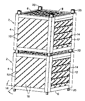
(0017] Fig. 1 shows a coalesces apparatus 2. The coalesces apparatus 2 has a
frame
member 4. The frame member 4 has a top portion 8 and a bottom portion 6. There
are a
plurality of coalescing plates 10 running parallel to each other supported by
the frame member 4.
The coalescing plates 10 have a corrugated bottom surface 12 to increase
coalescence in the
rising liquid droplets. The coalescing plates 10 have a flat top surface 14
without corrugations.
The coalescing plates 10 are inclined upwardly from the bottom portion 6 of
the frame member 4
at angle 16 from 45 to 60 degrees to the top portion 8. The coalescing plates
10 are spaced 18
between'/4 inch to 3 inches apart. There are interlocking members 20 extending
from the frame
member 4 for stacking the coalesces apparatus 2. Two coalesces apparatuses 2
are stacked
vertically.
[0018] As fluid flow that contains immiscible solids and liquids is passed
through the
coalesces apparatus 2 separation begins. The immiscible liquid (oil) droplets
rise to the bottom
corrugated surface of the coalescing plates 12. As droplets of the immiscible
liquid move up and
down the corrugations 12 they move at different speeds causing the droplets to
collide with each
other. These collisions cause the droplets to coalesce thus giving them a
bigger diameter. Once
the droplets pass through the coalesces they rise to the top 38 to form a
surface layer that can
easily be removed. Simultaneously the solids fall to the top flat surface 14
of the coalescing
8
CA 02389065 2002-06-05
plates 10. Because the coalescing plates 10 are angled 16 from the bottom
frame member 6 the
solids slide down the flat surface 14 of the coalesces plates and fall out of
the coalesces apparatus
2.
[0019] Fig 2 shows the coalesces apparatus 2 used in an oil water separator
tank 21. The
oil water separator tank 21 depicted is a type of oil-water separator tank
defined in U.S. Patent
Number 4,722,800 Oil-Water Separator issued February 2, 1988 to Gregory G.
Aymong. The oil
water separator tank 21 can have either a cylindrical cross-section (as
shown), or a rectangular
cross-section, and can have an access chamber. The tank has an inlet end 22
and an outlet end
26. Located near the inlet end 22 there is a means for channeling fluid flow
24 from the inlet end
22 through the coalesces apparatus 2 towards the outlet end 26. The tank also
has a sludge
baffle 28 extending from the bottom 30 of the coalesces apparatus 2 to the
bottom 32 of the tank
in order to prevent fluid from passing under the coalesces apparatus 2. There
are side plates 34
that extend from the coalesces apparatus 2 to the wall 36 of the separator
tank 21 to ensure that
fluid flow passes through the coalesces apparatus 2 (see figure 3). Once the
fluid flow is
channeled though the coalesces apparatus 2 separation occurs. The solids fall
to the bottom of
the tank near the sludge baffle 28. The oil droplets float to the top 38 of
the tank 21 creating an
oil layer that can be pumped out of the tank 21. The separated water layer is
on the bottom
portion of the tank 21 in the outlet end 26. The water can then flow through
the outlet end 26.
This same separation process is used in a separator tank with an access
chamber or with a
rectangular cross section.
[0020] As various changes could be made in the above construction and method
without
departing from the scope of the invention, it is intended that all matter
contained in the above
9
CA 02389065 2002-06-05
description as shown in the accompanying drawings shall be interpreted as
illustrative and not as
a limitation.