Note : Les descriptions sont présentées dans la langue officielle dans laquelle elles ont été soumises.
CA 02389540 2002-05-21
WO 01/36024 PCT/US00/28893
PRESSURE-RESPONSIVE FLOW REGULATOR AND DRUG DELIVERY
DEVICES EMPLOYING THE SAME
FIELD AND BACKGROUND OF THE INVENTION
The present invention relates to drug delivery systems and. in particular.
s it concerns a fluid flow regulator for regulating the flow of liquid
medications.
In many cases. it is desired to administer a fluid medication
continuously at a slow rate over a Given time period. The most common
technique for doing this is by adding the medication to a relatively large
amount of physiologically compatible liquid and delivering the resulting
mixture through an infusion.
This approach suffers from a number of disadvantages. Firstly, the
amounts of liquids generally used may in certain cases cause medical
complications. Secondly, the presence of an infusion greatly limits the
mobility
of the patient. And thirdly, the rate of delivery of the mixture may be
imprecise, depending both upon the ability of the operator to correctly adjust
the flow rate and on the liquid level within the infusion bag. The problem of
precision may be addressed by use of an electromechanical dosage regulator.
This. however, is a relatively expensive solution. and does not address the
remaining problems mentioned above.
An alternative approach to slow drug delivery is by absorption through
the skin by use of adhesive patches. This approach, however, gives very
non-uniform dosage, and can only deliver very small quantities of medication.
In an attempt to achieve more uniform dosages at a wide range of flow
rates, flow regulators have been developed based on the use of a
pressure-responsive flexible diaphragm. The principle of these regulators may
be understood by reference to U.S. Patents Nos. 4,343,30 and 5,421,363 to
Dan Bron which are hereby incorporated by reference. The Bron '305 reference
discloses a flow regulator for use in an infusion set. The flow regulator
includes
CA 02389540 2002-05-21
WO 01/36024 PCT/US00/28893
a body having a cavity divided into two chambers by a flexible diaphragm. The
first of these chambers is a pressure sensing chamber. The other is a valuing
chamber through which the drug flows. the outlet from that chamber being
centrally disposed underlying the diaphragm whereby flexing of the diaphragm
in one direction as a result of increased pressure in the other chamber
adjusts
the size of the flow path through the outlet. A rudimentary flow impedance
adjustment between the t,vo chambers is proposed as a means for adjusting the
flow rate.
The Bron '363 reference proposes an improved adjustment
configuration in which a tubular flow attenuator fits within the neck portion
of
a housing. The flow attenuator is formed with a pattern of grooves which,
together with the opposing surface, define a meander-type labyrinth. The
relative positions of an inlet and outlet along the labyrinth may be varied by
relative rotation between the flow attenuator and the neck portion, thereby
changing the operative length of the labyrinth and the consequent flow rate.
The diaphragm-based regulators of Bron provide significant advantages
over the slow-dosing techniques described above. Specifically, these
regulators
provide generally uniform dosing of medication at low flow rates, thereby
avoiding the need for the excessive dilution of conventional infusions. The
pressure-responsive nature of the regulation also ensures that supply pressure
variations are properly compensated. Nevertheless, these regulators suffer
from
a number of serious shortcomings. Most notably, the full range of adjustment,
even for the improved configuration of the '363 patent, corresponds to a range
of rotation significantly less than a full revolution. As a result, the
regulator is
either implemented so as to be limited to a fairly narrow range of flow rates
or
is overly sensitive to angular displacements offering a low degree of
precision
in selecting the flow rate.
A further shortcoming of the aforementioned Bron regulators is the
complexity of manufacturing high-precision meandering labyrinth grooves
around the internal surface of a cylindrical element.
CA 02389540 2002-05-21
WO 01/36024 PCT/US00/28893
U.S. Patent No. x.101,854 also to Bron discloses an alternative design of
diaphragm-based flow regulator which employs a flow-attenuating passageway
formed by opposing surfaces one of which has a helical groove. The use of a
helical groove provides considerable advantages of ease of production and
precision. However. no provision is offered for rendering such a helical
flow-attenuating passageway adjustable. Instead. adjustment is achieved by
changing the outlet geometry directly by raising or lowering the outlet
aperture
relative to the diaphragm.
Finally. it should be noted that all of the above-mentioned regulators
must be connected at all times to an external supply of medication, rendering
the drug delivery system a minimum of at least two separate parts and
somewhat bulky.
There is therefore a need for a simple diaphragm-based flow regulator,
suitable for use in medical applications, which would provide precise control
of
the flow rate over a wide range of rates. It would also be advantageous to
provide a compact drug delivery device which would provide
pressure-responsive regulation of drug release from a contained volume.
SUMMARY OF THE INVENTION
The present invention is a continuously-adjustable, pressure-responsive
flow regulator. The present invention also provides drug delivery devices
employing a flow regulator of this type.
According to the teachings of the present invention, in a fluid flow
regulator of a type having a variable outlet defined by a spacing beriveen an
outlet aperture and a flexible diaphragm. and in which the position of the
flexible diaphragm varies as a function of a pressure differential beriveen a
sensing chamber on a first side of the diaphragm and an outlet chamber on a
second side of the diaphragm, there is provided an adjustable flow impedance
configuration disposed in a flow path passing from a first point in
substantially
direct fluid communication with the sensing chamber to the outlet chamber. the
-,
i
CA 02389540 2002-05-21
WO 01/36024 PCT/US00/28893
adjustable flow impedance configuration comprising: (a) a first element
providing a first substantially cylindrical outer surface, reference being
made to
a central axis of the first cylindrical surface; and (b) a second element
providing a second substantially cylindrical inner surface deployed coaxially,
and in sliding contact. with the first surface, wherein at least one of the
first and
second cylindrical surfaces features at least one groove configured to define
a
flow-attenuating passageway between the first and second cylindrical surfaces,
the flow-attenuating passageway having a net flow vector substantially
parallel
to the axis, the first and second elements being configured such that axial
movement of the first element relative to the second element causes a
variation
in an extent of overlap between the first and second cylindrical surfaces,
thereby varyinff an operative length of the flow-attenuating passageway.
According to a further feature of the present invention, the at least one
groove is a helical groove.
According to a further feature of the present invention, the first element
features a first threaded adjustment portion and the second element features a
complementary threaded adjustment portion deployed in engagement with the
first threaded adjustment portion such that rotation of the first element
relative
to the second element about the axis generates movement of the first
?0 component relative to the second component along the axis.
According to a further feature of the present invention, the operative
length of the flow-attenuating passageway varies in a substantially continuous
manner with rotation of the first element relative to the second element about
the axis over a range of a plurality of revolutions of the relative rotation.
2~ According to a further feature of the present invention, the at least one
groove has at least a first portion configured to produce a flow-attenuating
passageway having a first cross-sectional area and a second portion configured
to produce a flow-attenuating passageway having a second cross-sectional area
greater than the first cross-sectional area.
30 There is also provided according to the teachings of the present
invention, a constant flow fluid delivery device comprising: (a) at least one
CA 02389540 2002-05-21
WO 01/36024 PCT/US00/28893
body component defining a cavity: (b) a flexible diaphragm deployed within
the cavity so as to divide the cavity into a storage chamber and an outlet-
side
chamber; (c) at least one flow-path-defining component associated with the
body so as to define a flow) path from a first point in substantially direct
fluid
~ communication with the storage chamber passing via a fluid flow restriction
to
the outlet-side chamber. the fluid flow restriction being formed as a
flow-attenuating passageway lying substantially on a virtual cylinder; (d) an
outlet from the outlet-side chamber, the outlet being configured such that
flexing of the diaphragm in a given direction in response to increased
pressure
in the storage chamber restricts flow through the outlet; and (e) a pressure
applicator deployed within the storage chamber so as to apply
above-atmospheric pressure to a fluid within the storage chamber. wherein at
least part of the storage chamber lies concentrically within the virtual
cylinder
of the flow-attenuating passageway.
According to a further feature of the present invention, the pressure
applicator includes a spring-loaded piston. Preferably. he spring-loaded
piston
is configured to be manually retractable to facilitate filling of the storage
chamber.
According to a further feature of the present invention. the pressure
applicator includes an inflatable balloon.
BRIEF DESCRIPTION OF THE DRAWINGS
The invention is herein described, by way of example only, with
reference to the accompanying drawings, wherein:
FIG. 1 is a cross-sectional view taken through a continuously-adjustable,
''~ pressure-responsive flow regulator. constructed and operative according to
the
teachings of the present invention;
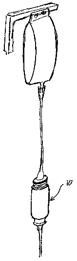
FIG. 2 is a schematic representation of an application of the flow
regulator of Figure 1 in an infusion line;
J
CA 02389540 2002-05-21
WO 01/36024 PCT/US00/28893
FIG. 3 is a cross-sectional view taken through a first embodiment of a
drug delivery device, constructed and operative according to the teachings of
the present invention, including the flow regulator of Figure l;
FIG. 4 is a schematic representation of an application of the drug
delivery device of Figure 3 as a slow-release syringe;
FIG. ~ is a cross-sectional view taken through a second embodiment of a
drug delivery device, constructed and operative according to the teachings of
the present invention, including the flow regulator of Figure l;
FIGS. 6A and 6B are schematic representations of an application of the
drug delivery device of Figure ~ showing it, respectively, during filling and
in
use as a slow-release syringe;
FIG. 7 is a cross-sectional view taken through a variant of the drug
delivery device of Figure 5;
FIG. 8A is a cross-sectional view taken through a
continuously-adjustable, pressure-responsive flow regulator equivalent to that
of Figure 1 but showing a reversed configuration; and
FIG. 8B is a partial enlarged view of the flow regulator of Figure 8A
showing a graduated sensitivity adjustment option.
DESCRIPTION OF THE PREFERRED EMBODIMENTS
The present invention is a continuously-adjustable, pressure-responsive
flow regulator. The present invention also provides drug delivery devices
employing a flow regulator of this type.
The principles and operation of flow regulators and drug delivery
devices according to the present invention may be better understood with
2~ reference to the drawings and the accompanying description.
Referring now to the drawings, Figure 1 shows a
continuously-adjustable, pressure-responsive fluid flow regulator, generally
designated 10, constructed and operative according to the teachings of the
present invention.
6
CA 02389540 2002-05-21
WO 01/36024 PCT/US00/28893
The principle of operation of flow regulator 10 is essentially similar to
that of the aforementioned diaphragm-based regulators known in the art. Thus,
in flow regulator 10 includes at least one body component 12 defining a
cavity,
and a flexible diaphragm 14 deployed within the cavity so as to divide the
cavity into an inlet-side chamber 16 and an outlet-side chamber 18. At least
one
flow-path-defining component 20 is associated with body component 12 so as
to define a flow path from a first point in substantially direct fluid
communication with inlet-side chamber 16 passing via a fluid flow restriction
22 to outlet-side chamber 18. An outlet 24 from outlet-side chamber 18 is
configured such that flexing of diaphragm 14 in a given direction in response
to
increased pressure in inlet-side chamber 16 restricts flow through outlet 24.
It is a particular feature of most preferred implementations of the present
invention that fluid flow restriction 22 is formed as an adjustable
flow-attenuating passageway at the interface between flow-path-defining
component 20 and body component 12 in such a manner that its operative
length may be changed by axial displacement of flow-path-defining component
relative to body component 12.
Thus, in the example shown, body component 12 provides a first
substantially cylindrical outer surface 26, and flow-path-defining component
20 20 provides a second substantially cylindrical inner surface 28 deployed
coaxially, and in sliding contact. with first cylindrical surface 26. At least
one
of first and second cylindrical surfaces 26 and 28 features at least one
groove
configured to define a flow-attenuating passageway between surfaces 26
and 28. This flow-attenuating passageway is configured to have a net flow
25 vector substantially parallel to the axis of the cylindrical surfaces.
Flow-path-defining component 20 and body component 12 are further
configured such that relative axial movement between them causes a variation
in an extent of overlap bet<veen the first and second cylindrical surfaces 26
and
28. thereby varying the operative length of the flow-attenuating passageway.
30 The flow-attenuating passageway is described as having a net flow
vector substantially parallel to the axis of the cylindrical surfaces. The
term
7
CA 02389540 2002-05-21
WO 01/36024 PCT/US00/28893
flow-attenuating passageway as used in the field of fluid flow regulation
refers
to a structure which produces an artificially elongated flow path between two
points. This may be achieved by introducing a meandering flow path
(labyrinth) beriveen the rivo end points or alternatively, in the case of a
cylindrical passageway. by producing an elongated helical flow path. In either
case. the term "net flow vector" is used herein to denote the net path
followed
by the fluid from its inlet into the passageway to its outlet therefrom
neglecting
the "detours" taken within the passageway itself.
In the present case, this net flow vector is described as "substantially
parallel" to the axis of the cylindrical surfaces to the extent that the
length of
the passageway traveled is a direct, typically linear, function of the axial
distance traveled along the cylinder. It should be noted that the net flow
path
may not be truly parallel to the axis since the angular disposition of the
inlet
and outlet about the axis need not be the same and typically varies during
adjustment, as will become clear below.
Groove 30 may be formed on either of first and second cylindrical
surfaces 26 and 28, i.e., as part of either body component 12 or
flow-path-defining component 20. Thus, the invention will be described herein
with reference to Figures 1-7 employing an example in which groove 30 is
?0 formed on surface 26 as part of body component 12. Figures 8A and 8B show
an equivalent regulator 10', constructed and operative according to the
teachings of the present invention. employing the reverse configuration.
As mentioned above, the "operative length'' of the flow-attenuating
passageway is a function of the extent of overlap between the first and second
?5 cylindrical surfaces 26 and 28. Specifically, in the case shown here that
groove
30 is formed on surface 26, surface 28 is delimited by a recess 36 which is
preferably formed as a general widening of the internal diameter of
flow-path-defining component 20 as shown. Thus, the length over which the
fluid flow is limited to the flow-attenuating passageway is set by the degree
of
30 overlapping contact between surfaces 26 and 28, starting from the left-hand
end
8
CA 02389540 2002-05-21
WO 01/36024 PCT/US00/28893
of groove 30 as shown and terminating at recess 36. This length is referred to
as the "operative length'' of the flow-attenuating passageway.
Turning now to the details of flow regulator 10 in more detail, in a
particularly preferred implementation of the present invention. groove 30 is
formed as a helical groove. This has advantages for the ease of manufacture
and level of precision with which the groove can be produced. Optionally,
more than one groove 30 can be deployed in a double- or triple-helix. although
a single helix is generally preferred.
In order to facilitate precise adjustment of the relative axial positions of
body component 12 and flow-path-defining component 20. these are preferably
provided with complementary threaded adjustment portions 32 and 34,
respectively. These threaded adjustment portions are deployed in engagement
with each other such that rotation of flow-path-defining component 20 relative
to body component 12 about the central axis generates slow and
1 ~ accurately-controllable relative movement between them in an axial
direction.
The pitch of the threaded portions is preferably chosen such that the full
range
of adjustment of the operative length of the flow-attenuating passageway
corresponds to at least two, preferably at least three, and most preferably no
less than five, complete turns of flow-path-defining component 20 relative to
?0 body component 12 about the central axis. This facilitates precise
adjustment of
the flow rate across substantially the full range of flow rates accommodated
by
flow regulator 10.
It should be noted that the present invention is applicable to applications
over a wide range of flow rates. Thus, at one extreme. the device may be used
for infusion rates of up to about I O liters per hour. At the other extreme,
it may
be used to advantage such as in the dispensing device applications of the
present invention described below for dispensing rates in the range of
milliliters per hour or even tenths of milliliters. Where designed
specifically for
a given set of applications requiring only a given sub-range of the flow rates
30 mentioned, the size of groove 30 may be chosen to provide maximum
sensitivity over the intended sub-range. According to one particularly
preferred
9
CA 02389540 2002-05-21
WO 01/36024 PCT/US00/28893
option. flow regulator 10 is implemented with the capability of multiple-stage
graduated sensitivity adjustment as will now be described with reference to
Figure 8B.
Specifically, according to the preferred option illustrated in Figure 8B,
Groove 30 is formed with a variable cross-sectional area in such a manner as
to
provide sensitivity of adjustment appropriate to the flow rate setting. In the
example shown, the groove is subdivided into three portions. The first portion
to come into overlapping relation. designated 30a, has a relatively large
cross-sectional area to provide flow rate adjustment suited to higher flow
rates.
The middle portion, designated 30b, has a smaller area suited to finer
adjustments. The third portion. designated 30c, which only comes into
overlapping relation at the lowest flow rates, has a small cross-sectional
area to
provide the required sensitivity of adjustment at such low rates. By way of
example, flow regulator 10 may be configured such that the three ranges
correspond respectively to flow rates from 10 liters/hour (1/hr) down to 1
I/hr,
from 1 1/hr down to 10 ml/hr, and from 10 ml/hr down to 100~1/hr.
Clearly, the subdivision of groove 30 into three portions in the manner
described is only one example of the use of a variable groove size. In an
alternative preferred implementation (not shown), the groove size varies in a
continuous,, or near continuous. manner to provide what approximates to a
logarithmic scale adjustment. In a further preferred alternative (not shown),
the
groove size may be varied in a continuous, or near continuous, manner in the
reverse direction, i.e., such that the smaller cross-section is first to come
into
overlapping relation with the opposing surface. This latter option may be used
to provide linear, or near-linear. variation of the flow rate with the number
of
turns through which the adjustment mechanism is turned.
At least one scale 38 is typically provided to indicate the flow rate to
which the regulator is set. In a preferred implementation, scale 38 is
deployed
to provide an indication based on axial displacement between body component
12 and flow-path-defining component 20. Adjustment along this scale by use of
multiple turns offers much higher resolutions than could reliably be achieved
CA 02389540 2002-05-21
WO 01/36024 PCT/US00/28893
using the single-revolution adjustment proposed by the aforementioned U.S.
Patent No. x.421.363.
To complete the structural description of regulator 10, it will be noted
that body component 12 preferably also serves to define a seat 42 defining the
position of the periphery of diaphragm 14. at least one radial passage 44 from
inlet-side chamber 16 to flow restriction 22. at least one radial passage 46
from
flow restriction 22 to outlet-side chamber 18. and the outlet aperture 24. For
conventional in-line flow regulation applications, such as the infusion
regulation application shown schematically in Figure 2. an adapter element 48
is added to provide the inlet connection 50 of regulator 10. Adapter element
48
also retains diaphragm 14 to prevent it becoming removed from seat 42 in the
event of a reverse flow (cases of which will be mentioned below). but is
configured to ensure an unobstructed flow path to passageway 44.
In use, flow regulator 10 is connected in line, for example as shown in
Figure 2, and is adjusted by rotation of flow-path-defining component 20 to
the
required flow rate setting. Preferably, flow-path-defining component 20 is
configured so provide one or both of a fully closed and a fully open extreme
state. The fully closed state may conveniently be provided by forming
flow-path-defining component 20 such that one of its seals 52 overlies and
obstructs passageway 44 in the extreme low-flow position. The fully open
"short-circuit" state may conveniently be provided by ensuring that recess 36
moves beyond the start of groove 30 in the extreme high-flow position.
Turning now to Figures 3-7, according to further embodiments of the
present invention. the regulator structure described thus far forms the basis
of
highly-compact. self contained. constant-flow fluid delivery devices which
may be used as a replacement for slow-dosing arrangements such as syringe
pumps. Specifically, the hollow. coaxial, cylindrical form of both body
component 12 and flow-path-defining component 20 provides a hollow core
which serves as a storage chamber disposed concentrically at least partially
within the virtual cylinder of the flow-attenuating passageway. The fluid
delivery devices are completed by a pressure applicator deployed within this
CA 02389540 2002-05-21
WO 01/36024 PCT/US00/28893
storage chamber replacing adapter 48 of Figure 1 ) so as to apply
above-atmospheric pressure to a fluid within the storage chamber, thereby
dispensing the fluid.
In a first example shown in Figures 3 and 4, the pressure applicator is
employs a spring-loaded piston 54 which is urged forward in relation to an
insert sleeve 56 by a helical spring 58. The external and front end surfaces
of
insert sleeve 56 are similar to the corresponding surfaces of adapter 48
described above. In this case, piston 54 extends from the rear of insert
sleeve
56 so as to be manually retractable. This allows manual filling of the storage
chamber by retraction of the piston while the front of the dispenser is
immersed
in the fluid. Optionally, this and other examples of the dispenser may be
configured so that diaphragm 14 becomes lifted slightly from seat 42 by the
reverse pressure during filling, thereby allowing the fluid flow to bypass
flow
restriction 22. Figure 4 shows a typical application of this dispenser,
directly
connected to a needle.
Figures ~, 6A and 6B show a fluid dispenser similar to that of Figures 3
and 4 in which the spring-loaded piston 60 is implemented as a closed unit not
manually retractable. In this case, filling must be done by application of
back
pressure, such as with a syringe (Figure 6A). Once full, the syringe is
removed
?0 and the dispenser may be sealed and stored until required for use. A needle
may then be attached (Figure 6B) for use in the same manner as the previous
embodiment.
Finally. turning to Figure 7, there is shown an additional embodiment of
a fluid dispenser, functionally identical to that of Figure 5. In this case,
the
2~ pressure applicator is implemented using an inflatable balloon 62. Balloon
62
may be made from a range of medical grade materials including, but not
limited to, silicone rubber. latex and stainless steel.
In all other respects, the structure and operation of the dispensing
devices of Figures 3-7 are fully analogous to, and will be understood by
30 reference to, those of regulator 10 described above in detail with
reference to
Figures 1 and 2.
12
CA 02389540 2002-05-21
WO 01/36024 PCT/US00/28893
It will be appreciated that the above descriptions are intended only to
serve as examples. and that many other embodiments are possible within the
spirit and the scope of the present invention.
13