Note : Les descriptions sont présentées dans la langue officielle dans laquelle elles ont été soumises.
w ~ i ~i" w i~~~ ~
CA 02390397 2002-07-03
JJ-11 700CA
TITLE: OIL TANK SYSTEM FOR ENGINE
FIELD OF THE INVENTION
The present invention relates to an oil tank
system for an engine, and more particularly to an oil
tank system for a dry sump type engine in which an oil
tank for storing engine oil is provided independently
from the engine, which oil tank system is mainly adapted
for an engine mounted on a small watercraft.
BACKGROUND OF THE INVENTION
In recent years, even for small watercrafts
(particularly, personal watercrafts), it has been
examined to mount four-cycle engines from the viewpoint
of reducing environmental pollution due to exhaust gas
and also reducing noise.
Since personal watercrafts are configured such
that an engine is substantially enclosed in a narrow
space formed by a hull and a deck, the engine is required
to be made compact; however, since a four-cycle engine
has a valve system and further has a large cylinder head,
the size of the four-cycle engine tends to become large.
On the other hand, since four-cycle engine
require forced lubrication of engine oil, the engine oil
is liable to be entrained in breathing gas circulating in
a crankcase. In order to subject the breathing gas to
gas-liquid separation and introduce the breathing gas,
from which engine oil has been separated, again into a
combustion chamber, there have been proposed various
breather systems.
Further, in conventional four-cycle engines, a
breather chamber is formed only in a cylinder head cover
(see Japanese Patent Laid-open No. Hei 10-252440).
In conventional four-cycle engines, since a
breather chamber is formed only in a cylinder head cover,
- 1 -
_ i ~', n i ii i
CA 02390397 2002-07-03
JJ-11 700CA
the entire size, particularly, the entire height of the
engine becomes large.
Accordingly, it has been not easy to mount a
four-cycle engine in a small watercraft body.
An object of the present invention is to solve
the above-described problems and to provide an oil tank
system for an engine, which is capable of reducing the
entire size, particularly, the entire height of the
engine.
SUMMARY OF THE INVENTION
To achieve the above object, according to the
present invention, there is provided an oil tank system
for an engine, characterized in that a dry sump type
engine having an oil tank for storing engine oil is
provided independently from the engine, and a breather
chamber is defined in the oil tank, and the breather
chamber is communicated to the engine.
According to an aspect of the invention, in
addition to the configuration of the invention described
above, the oil tank is composed of divided cases joined
to each other, and the breather chamber is formed by
joining the divided cases to each other.
According to an another aspect of the
invention, in addition to the configuration of the
invention described in claim 1 or 2, a breathing gas
inlet for supplying breathing gas to the breather chamber
is provided in an upper portion of the oil tank, and a
breathing gas outlet for discharging the breathing gas
from the breather chamber is provided at a position lower
than that of the breathing gas inlet; and an oil return
passage for returning oil having been separated in the
breather chamber is provided in the oil tank.
According to an yet another invention of the
invention, in addition to the configuration of the
- 2 -
~', I ~I l ~4 ,~ I
CA 02390397 2002-07-03
JJ-11 700CA
invention described above, the divided cases are joined
to each other via a gasket; the breather chamber is
partially partitioned into a first breather chamber and a
second breather chamber by the gasket; and the breathing
gas inlet is provided in the first breather chamber and
the breathing gas outlet is provided in the second
breather chamber.
According to another aspect of the invention,
in addition to the configuration of the invention
described in above, the oil tank forms a cover portion of
an AC generator disposed at an end of a crankshaft of the
engine.
According to yet another aspect of the
invention, in addition to the configuration of the
invention described above, a pulser for taking out a
signal is provided on an outer periphery of the AC
generator in such a manner as to be overlapped to the oil
tank in a direction along the crankshaft.
According to another aspect of the invention,
in addition to the configuration of the invention
described above, a water-cooled type oil cooler
accommodating portion is formed integrally with the oil
tank.
According to yet another aspect of the
invention, in addition to the configuration of the
invention described above, an oil filter is provided in
the oil tank; and the oil cooler is interposed in an oil
passage extending from the oil filer to a main gallery of
the engine.
According to yet another aspect of the
invention, in addition to the configuration of the
invention described, above, the engine is an engine,
mounted on a small watercraft, for driving a jet pump;
and cooling water from a cooling takeoff portion in the
- 3 -
i , i~ i n i
."
CA 02390397 2002-07-03
JJ-11 700CA
jet pump is first supplied to the water-cooled type oil
cooler accommodating portion.
According to another aspect of the invention,
in addition to the configuration of the invention
described above, the engine is mounted on a small
watercraft; and the breather chamber forms an oil sump at
the time of turn-over of the watercraft.
According to yet another aspect of the
invention, in addition to the configuration of the
invention described above, the engine is mounted on a
small watercraft; and the return passage forms a
breathing passage at the time of turn-over of the
watercraft.
According to another aspect of the invention,
in addition to the configuration of the invention
described above, the engine is mounted on a small
watercraft; and a sump portion for oil which counter
flows in the return passage at the time of turn-over of
the watercraft is provided in an upper portion (lower
portion, at the time of turn-over of the watercraft) of
the second breather chamber.
BRIEF DESCRIPTION OF THE DRAWINGS
Preferred embodiments of the invention are
shown in the drawings, wherein:
Figure 1 FIG. 1 is a schematic side view
showing one example of a personal watercraft using one
embodiment of an oil tank system for an engine according
to the present invention.
FIG. 2 is a plan view of the personal
watercraft shown in FIG. 1.
FIG. 3 is a partial, enlarged sectional view
taken on line III-III of FIG. 1 (with parts partially
omitted).
- 4 -
' CA 02390397 2005-04-19
FIG. 4 is a partial, enlarged sectional view
taken on line IV-IV of FIG. 1, mainly showing the engine
20.
FIG. 5 is a right side view of the engine 20.
FIG. 6 is a left side view of the engine 20.
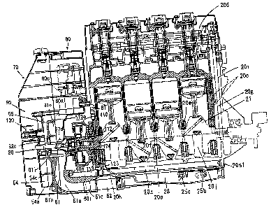
FIG. 7 is a schematic perspective view of the
engine 20 as seen from an obliquely rear direction.
FIG. 8 is an enlarged view of a portion shown
in FIG. 5.
FIGS. 9(a) to 9(d) are views showing the tank
main body 60, wherein FIG. 9(a) is a plan view, FIG. 9(b)
is a front view, FIG. 9 (c) is a sectional view taken on
line c-c of FIG. 9(b), and FIG. 9(d) is a sectional view
taken on line b-b of FIG. 9(a).
FIG. 10 is a back view of the tank main body
60.
FIG. 11(e) is a sectional view taken on line e-
a of FIG. 9(b) and FIG. 11(f) is a sectional view taken
on line f-f of FIG. 9(b).
FIGS. 12(a) to 12(d) are views showing the
cover 70, wherein FIG. 12 (a) is a front view, FIG. 12 (b)
is a sectional view taken on line b-b of FIG. 12(a), FIG.
12(c) is a sectional view taken on line c-c of FIG.
12(a), and FIG. 12(d) is a sectional view taken on line
d-d of FIG. 12 (a) .
FIGS. 13(a) to 13(c) are views showing the
cover 70, wherein FIG. 13(a) is a back view, FIG. 13(b)
is a view seen along a direction shown by an arrow "b" in
FIG. 13(a), and FIG. 13(c) is a sectional view taken on
line c-c of FIG. 13(a).
FIG. 14 is a sectional view taken on line XIV-
XIV of FIG. 12(a).
FIG. 15 is an enlarged view of a portion shown
in FIG. 4.
- 5 -
i~ i n
CA 02390397 2002-07-03
JJ-11 700CA
FIGS. 16 (a) and 16 (b) are views showing an oil
pump 80, wherein FIG. 16(a) is a front view and FIG.
16(b) is a sectional view taken on line b-b of FIG.
16 (a) .
FIG. 17 is a diagram showing an oil circulation
route.
FIGS. 18(a) and 18(b) are schematic views
showing states of the engine 20 and the oil tank 50 at
the time of turn-over of a watercraft 10, wherein FIG.
18(a) is a front view and FIG. 18(b) is a side view.
FIGS. 19(a) and 19(b) are views illustrating
the return of oil when the turned-over watercraft 10 is
recovered (returned to a normal posture), wherein FIG.
19(a) is a front view and FIG. 19(b) is a side view.
DETAILED DESCRIPTION OF THE PREFERRED EMBODIMENTS
Hereinafter, preferred embodiments of the
present invention will be described with reference to the
drawings.
FIG. 1 is a schematic side view showing one
example of a personal watercraft to which one embodiment
of an oil tank system for an engine according to the
present invention is applied; FIG. 2 is a plan view of
the personal watercraft; and FIG. 3 is a partial,
enlarged sectional view taken on line III-III of FIG. 1
(with parts partially omitted).
Referring to these figures (particularly, to
FIG. 1), a personal watercraft 10 is a saddle type small
watercraft, which is operable by a driver who sits on a
seat 12 provided on a watercraft body 11 and holds a
steering handlebar 13 provided with a throttle lever.
The watercraft body 11 has a floating structure
that a hull 14 is joined to a deck 15 so as to form a
space 16 therein. In the space 16, an engine 20 is
mounted on the hull 14, and a jet pump or jet propelling
- 6 -
w ~ L ';',, ' p I il I
CA 02390397 2002-07-03
JJ-11 700CA
pump 30 functioning as propelling means to be driven by
the engine 20 is provided on a rear portion of the hull
14.
The jet pump 30 has a flow passage 33 extending
from a water inlet 17 opened in a bottom of the hull 14
to both a jet port 31 opened in a rear end portion of the
hull 14 and a nozzle 32, and an impeller 34 disposed in
the flow passage 33. A shaft 35 of the impeller 34 is
connected to an output shaf t 21 of the engine 2 0 . When
the impeller 34 is rotated by the engine 20, water taken
in via the water inlet 17 is jetted from the jet port 31
via the nozzle 32, to propel the watercraft body 11. A
rotational speed of the engine 20, that is, a propelling
force of the jet pump 30 is controlled by a turning
operation of a throttle lever 13a (see FIG. 2) of the
steering handlebar 13. The nozzle 32 is coupled to the
steering handlebar 13 via a steering wire (not shown),
and is turned by operation of the steering handlebar 13,
to change a running course.
In the figures, reference numeral 40 denotes a
fuel tank, and reference numeral 41 denotes a storing
chamber.
FIG. 4 is a view mainly showing the engine 20,
which is a partial, enlarged sectional view taken on line
IV-IV of FIG. 1 (with parts partially omitted); FIG. 5 is
a right side view of the engine 20; FIG. 6 is a left side
view of the engine 20; FIG. 7 is a schematic perspective
view of the engine 20 as seen from an obliquely rearward
direction, and FIG. 8 is an enlarged view of a portion
shown in FIG. 5.
The engine 20 is a DOHC type in-line four-
cylinder/four-cycle engine, which is particularly of a
dry sump type according to this embodiment, wherein as
shown in FIGS. 1 and 5, a crankshaft 21 of the engine 20
_ 7 _
i n i ~i i
CA 02390397 2002-07-03
JJ-11 700CA
extends along the longitudinal direction of the
watercraft body 11.
As shown in FIGS. 4 and 7, a surge tank (intake
chamber) 22 communicated to an intake port and an inter
s cooler 23 connected to the surge tank 22 are disposed on
the left side of the engine 20 as seen in the running
direction of the watercraft body 11. An exhaust manifold
24 (see FIG. 6), which is connected and communicated to
exhaust ports 200, is disposed on the right side of the
engine 20.
As shown in FIGS. 6 and 7, a turbo-charger 25
is disposed at the back of the engine 20. An exhaust
outlet 240 of the exhaust manifold 24 is connected to a
turbine portion 25T of the turbo-charger 25, and the
inter-cooler 23 is connected to a compressor portion 25C
of the turbo-charger 25 via piping 26 (see FIG. 7) . In
FIG. 7, reference numerals 23a and 23b denote cooling
hoses connected to the inter-cooler 23.
After used for rotating a turbine in the
turbine portion 25T of the turbo-charger 25, as shown in
FIGS. 1 and 2, an exhaust gas passes piping 27a, a
counter-flow preventing chamber 27b for preventing
counter-flow upon turn-over of the watercraft body 11
(permeation of water in the turbo-charger 25 and the
like), a water muffler 27c, and an exhaust/drainage pipe
27d, and flows in a water stream caused by a jet pump 30.
As shown in FIGS. 4 to 8, in a front portion of
the engine 20 as seen in the running direction of the
watercraft body 11 (equivalent to a left portion in FIGS.
1 and 5), an oil tank 50 and an oil pump 80 integrated
with the oil tank 50 are provided on an extension of the
crankshaft 21. The oil pump 80 is provided in the oil
tank 50.
The oil tank 50 includes a tank main body (one
divided case) 60 joined to a front plane of the engine
_ g -
~I il
CA 02390397 2002-07-03
JJ-11 700CA
2 0 , and a cover ( the other divided case ) 7 0 j oined to a
front plane of the tank main body 60.
FIGS. 9(a) to 9(d) are views showing the tank
main body 60, wherein FIG. 9(a) is a plan view, FIG. 9(b)
is a front view, FIG. 9(c) is a sectional view taken on
line c-c of FIG. 9 (b) , and FIG. 9 (d) is a sectional view
taken on line b-b of FIG. 9(a); FIG. 10 is a back view of
the tank main body 60; and FIG. 11(e) is a sectional view
taken on line e-a of FIG. 9(b) and FIG. 11(f) is a
sectional view taken on line f-f of FIG. 9(b).
FIGS. 12(a) to 12(d) are views showing the
cover 70, wherein FIG. 12 (a) is a front view, FIG. 12 (b)
is a sectional view taken on line b-b of FIG. 12(a), FIG.
12(c) is a sectional view taken on line c-c of FIG.
12(a), and FIG. 12(d) is a sectional view taken on line
d-d of FIG. 12(a); FIGS. 13(a) to 13(c) are views showing
the cover 70, wherein FIG. 13(a) is a back view, FIG.
13(b) is a view seen in the direction shown by an arrow
"b" in FIG. 13(a), and FIG. 13(c) is a sectional view
taken on line c-c of FIG. 13(a); FIG. 14 is a sectional
view taken on line XIV-XIV of FIG. 12(a); and FIG. 15 is
an enlarged view of a portion shown in FIG. 4.
Referring to FIGS. 9 and 10, the tank main body
60 includes a contact plane 61 joined to the front plane
of the engine 20, a contact plane 62 jointed to the cover
70, a mounting plane 63 on which the oil pump 80 is
mounted, a mounting portion 64 on which a water-cooled
type oil cooler 90 to be described later is mounted, an
oil storing portion 65 which is defined by partition
walls forming the mounting planes and the like and outer
walls and is formed into a vertically-elongated shape as
a whole, a cover portion 66 for covering drive chambers
for an ACG to be described later, a balancer shaft, and a
starter motor. The tank main body 60 also includes a
first sub-breather chamber 67 to be fully described later
- g -
i ~, i~ i Gi i
CA 02390397 2002-07-03
JJ-11 700CA
and a mounting portion 68 on which an oil filter 100 to
be described later is mounted.
A plurality of baffle plates 65a are formed in
the oil storing portion 65.
Referring to FIGS. 5 and 8 (particularly to
FIG. 8), reference numeral 110 denotes an ACG rotor,
which is fixed, together with a coupling 111, to a
leading end of the crankshaft 21 with a bolt 112. The
coupling 111 is coupled to a coupling 89 fixed to a rear
end of a pump shaft to be described later.
Referring to FIGS. 4, 5 and 8, reference
numeral 113 denotes a balancer driving gear, which gear
113 is fixed to a back surface of the ACG rotor 110. As
shown in FIG. 4, the gear 113 is meshed, via an idle gear
116, with a balancer gear 115 fixed to a leading end of a
balancer 1148 (see FIG. 6) disposed in parallel to the
crankshaft 21 on the right side in the engine 20 (left
side in FIG. 4), so that the gear 113 can rotate the
balancer 1148. The gear 113 is also directly meshed with
a gear 117 fixed on a leading end of a balancer 114L
disposed in parallel to the crankshaft 21 on the left
side in the engine 20 (right side in FIG. 4), so that the
gear 113 can rotate the balancer 114L in a direction
reversed to the rotating direction of the balancer 1148.
In FIG. 4, reference numeral 120 denotes a
starter motor, which is provided with a pinion gear 121
meshed with a starter gear 123 via a reduction gear 122.
The starter gear 123 is, as shown in FIG. 8, connected to
the crankshaft 21 via a one-way clutch 124.
Referring to FIGS. 8, 9 and 10, the cover
portion 66 of the tank main body 60 has an ACG cover
portion 66a for covering the ACG rotor 110, the balancer
driving gear 113, a starter gear 123, a coupling cover
portion 66b for covering the coupling 111 portion, a
right balancer driving system cover portion 66c for
- 10 -
i~ r~i Gi i
CA 02390397 2002-07-03
JJ-11 700CA
covering the balancer gear 115 and the idle gear 116, a
left balancer driving system cover portion 66d for
covering the balancer gear 117, and a starter driving
system cover portion 66e for covering the pinion gear 121
of the starter motor 120 and the reduction gear 122. In
these figures, reference numeral 66f denotes a hole for
supporting a shaft of the reduction gear 122.
In FIG. 8, reference numeral 118 denotes a
pulser, provided on an outer periphery of the ACG, for
taking out a pulse signal. In the ACG cover portion 66a,
the pulser 118 is mounted on the coupling cover portion
66b, and accordingly, the pulser 118 is overlapped to the
oil tank 50 in the axial direction of the crank shaft 21.
The tank main body 60 configured as described
above is joined to the front plane of the engine 20 at
its contact plane 61 in a state that the above-described
portions of the tank main body 60 are covered with the
cover portion 66, and is integrally fixed to the front
plane of the engine 20 with bolts (not shown). It is to
be noted that after the oil pump 80 and the oil cooler 90
to be described later are mounted to the tank main body
60, the tank main body 60 is mounted to the front plane
of the engine 20.
Referring to FIGS. 12 to 14, the cover 70
includes a contact plane 71 joined to the tank main body
60, an oil supply port 72, a pressing portion 73 for
pressing a relief valve to be described later, an oil
cooler accommodating portion 74 for accommodating the oil
cooler to be described later, an oil storing portion 75
defined by the outer wall and partition walls, and the
second sub-breather chamber 77 to be fully described
later.
A plurality of baffle plates 75a are formed in
the oil storing portion 75.
- 11 -
CA 02390397 2002-07-03
JJ-11 700CA
FIGS. 16(a) and 16(b) are views showing the oil
pump 80, wherein FIG. 16(a) is a front view and FIG.
16(b) is a sectional view taken on line b-b of FIG.
16 (a) .
Referring to FIGS. 16 (a) and 16 (b) and FIG. 8,
the oil pump 80 includes a first case 81 joined to the
tank main body 60, a second case 82 jointed to the first
case 81, a pump shaft 83 provided so as to pass through
the first and second cases 81 and 82, an oil recovery
inner rotor 84a connected to the pump shaft 83 ~in the
first case 81, an outer rotor 84b rotatably provided on
the outer periphery of the inner rotor 84a, an oil supply
inner rotor 85a connected to the pump shaft 83 in the
second case 82, and an outer rotor 85b rotatably provided
on the outer periphery of the inner rotor 85a. In the
figures, reference numeral 86 denotes a dowel pin.
The oil recovery inner rotor 84a and the outer
rotor 84b form an oil recover pump in cooperation with
the first case 81, and the oil supply inner rotor 85a and
the outer rotor 85b form an oil supply pump in
cooperation with the first and second cases 81 and 82.
The oil pump 80 is assembled as shown in FIGS.
16(a) and 16(b) and the first case 81 is connected to the
second case 82 with a bolt 87; the contact plane 81a, to
be joined to the tank main body 60, of the first case 81
is joined to the contact plane 69 (see FIGS. 9(a) and
9(b)) which has the same shape as that of the contact
plane 81a and is formed on the front plane of the oil
tank main body 60; and a bolt 88 (see FIG. 8) is inserted
in a hole 80a passing through the first and second cases
81 and 82, whereby the oil pump 80 is mounted to the
front plane of the tank main body 60.
After the oil pump 80 is mounted to the tank
main body 60, a coupling 89 is fixed, from the back
- 12 -
I I il I
CA 02390397 2002-07-03
JJ-11 700CA
surface side of the tank main body 60, to a rear end of
the pump shaft 83 with a bolt 89a.
After the oil pump 80 and its coupling 89 are
mounted to the tank main body 60, the oil cooler 90 to be
described later is mounted to the tank main body 60, and
then the tank main body 60 is mounted to the front plane
of the engine 20 in such a manner that the coupling 89 is
coupled to the coupling 111 as described above.
Referring to FIGS. 6 and 9(b), the water-cooled
type oil cooler 90 is mounted to the front surface side
of the oil cooler 90 mounting portion 64 of the tank main
body 60.
The mounting portion 64 of the tank main body
60 has an upper hole 64a and a lower hole 64b
communicated to an oil passage to be described later.
As shown in FIG. 6, the oil cooler 90 has a
plurality of heat exchange plates 91 allowing oil to pass
therethrough, an oil inlet pipe 92 communicated to the
insides of upper portions of the plates 91, an oil outlet
pipe 93 communicated to the insides of lower portions of
the plates 91, and flange portions 94 and 95 for mounting
the oil cooler 90 to the tank main body 60.
The oil cooler 90 is mounted to the mounting
portion 64 of the tank main body 60 by fastening the
flange portions 94 and 95 to the tank main body 60 with
bolts (not shown) in a state that the inlet pipe 92 is
connected to the upper hole 64a of the tank main body 60
and the outlet pipe 93 is connected to the lower hole 64b
of the tank main body 60. In FIG. 15, reference numeral
96 denotes a bolt insertion hole provided in each of the
flange portions 94 and 95.
A cooling water introducing pipe 97,
communicated to a hole 64c (see FIG. 15) opened in the
mounting portion 64, for introducing cooling water in the
mounting portion 64 and the oil cooler accommodating
- 13 -
." ; i i~ i n i
CA 02390397 2002-07-03
JJ-11 700CA
portion 74 of the cover 70 is provided in the tank main
body 60. The cover 70 is, as shown in FIGS. 12(a) to
12(d), FIGS. 13(a) to 13(c), and FIG. 14, provided with a
water discharge pipe 78. A cooling water hose 97a from a
cooling water takeoff portion 30a (see FIG. 7) in the jet
pump 30 is connected to the introducing pipe 97 directly,
that is, without interposition of any cooling object
therebetween, and an drainage pipe 23c is, as shown in
FIG. 6, connected to the discharge pipe 78. Water from
the drainage pipe 78 is supplied to a water jacket of the
exhaust manifold 24 via the drainage pipe 23c.
After the tank main body 60, the oil pump 80,
and the oil cooler 90 are mounted on the front plane of
the engine 20 as described above, as shown in FIG. 8 and
FIGS. 16(a) and 16(b), a rear end 131 of a relief valve
130 is fitted in a hole 82a formed in a front plane of
the second case 82 of the oil pump 80 and the cover 70 is
joined to a front plane of the tank main body 60 in such
a manner that a leading end 132 of the relief valve 130
is pressed by the above-described pressing portion 73,
and the cover 7 0 i s f fixed to the tank main body 6 0 wi th
bolts (not shown). In FIG. 12(a), reference numeral 76
denotes each of bolt insertion holes allowing the bolts
for fixing the cover 70 to the tank main body 60 to pass
therethrough. As is apparent from FIG. 8, the relief
valve 130 is horizontally disposed.
In a state that the cover 70 is joined to the
tank main body 60, a single vertically-elongated oil
storing portion is formed by both the oil storing
portions 65 and 75. Further, by joining the cover 70 to
the tank main body 60, the baffle plates 65a and 75a,
which are formed in both the oil storing portions in such
a manner as to be opposed to each other, are joined to
each other.
- 14 -
I I II I
CA 02390397 2002-07-03
JJ-11 700CA
An oil filter 100 is mounted to the oil filter
100 mounting portion 68 of the tank main body 60.
In a state that the engine 20 is mounted on the
watercraft body 11, the engine 20 and the oil filter 100
are aligned with an opening 15a of the deck 15 as shown
in FIGS. 2 and 4. The opening 15a of the deck 15 is
opened by removing the seat 12, which is removably
mounted on the watercraft body 11, from the watercraft
body 11.
In a state that the oil tank 50 (including the
tank main body 60, the cover 70, and the oil pump 80, the
oil cooler 90 and the relief valve 130 contained in the
cover 70) is mounted to the front plane of the engine 20
and tine oil filter 100 is mounted to the mounting
portion 68 of the tank main body 60 as described above,
the following oil passages are formed.
Referring to FIGS. 5 and 8, an oil recovery
passage 51 is formed between the front plane of the tank
main body 60 and the back surface of the first case 81 of
the oil pump 80. The recovery passage 51 includes an oil
passage 51a (see FIG. 9(b)) formed on the tank main body
60 side, and an oil passage 51b which is formed in a
portion, on the first case 81 side, of the oil pump 80 in
such a manner as to be opposed to the oil passage 51a.
A lower end 51c of the oil recovery passage 51
is communicated to an oil pan 28 of the engine 20 via a
pipe 52, and an upper end 51d of the oil recovery passage
51 is communicated to a recovery oil suction port 81i
formed in a portion, on the first case 81 side, of the
oil pump 80.
Similarly, a recovery oil discharge passage 53
between the front plane of the tank main body 60 and the
back surface of the first case 81 of the oil pump 80 is
formed. The recovery oil discharge passage 53 includes
an oil passage 53a (see FIG. 9(b)) formed on the tank
- 15 -
i ~ n i ii i
CA 02390397 2002-07-03
JJ-11 700CA
main body 60 side, and a recovery oil discharge port 810
which is formed in a portion, on the first case 81 side,
of the oil pump 80 in such a manner as to be opposed to
the oil passage 53a.
An upper end 53b of the recovery oil discharge
passage 53 is opened in the oil tank 50 (that is, in the
oil storing portions) (see FIGS. 9(b) and 15).
Referring to FIG. 8, a supplied oil suction
passage 54 and a supplied oil discharge passage 55 are
formed between the front plane of the first case 81 of
the oil pump 80 and the back surface of the second case
82 of the oil pump 80.
A lower end 54a of the suction passage 54 is
opened in the oil tank 50 (that is, in the oil storing
portions), and an upper end 54b of the suction passage 54
is communicated to a supplied oil suction port 82i of an
oil supply pump (see FIG. 16(b)). A screen oil filter
54c is provided in the suction passage 54.
A lower end 55a of the discharge passage 55 is
communicated to a supplied oil discharge port 820 of the
oil supply pump. An upper end 55b of the discharge
passage 55 passes through an upper portion of the first
case 81 in the horizontal direction, to be communicated
to a horizontal hole 60a formed in the tank main body 60
(see FIGS. 9(b) and 15). As shown in FIGS. 8, 9(b) and
15, the horizontal hole 60a is communicated to a vertical
hole 60b formed in the tank main body 60. An upper end
60c of the vertical hole 60b is opened in the oil filter
100 mounting portion 68 (see FIGS. 9(a) and 11(e)) in
such a manner as to be formed into a ring-shape in a plan
view. An oil flow-in passage 101 of the oil filter 100
is communicated to the upper end 60c of the vertical hole
60b.
The above-described relief valve 130 mounting
hole 82a is opened in the discharge passage, and the
- 16 -
I~ I il I
CA 02390397 2002-07-03
JJ-11 700CA
relief valve 130 is mounted in the mounting hole 82a as
described above.
A male screw is provided in an oil outlet pipe
102 in the oil filter 100. The oil filter 100 is mounted
to the mounting portion 68 of the tank main body 60 by
screwing the male screw portion of the oil outlet pipe
102 in a female thread hole 60d formed in the mounting
portion 68 of the tank main body 60 (see FIGS. 9(a),
9 (b) , 11 (e) and 15) .
A peripheral wall 68a is formed integrally with
the mounting portion 68. An oil receiving portion 68c is
formed by the peripheral wall 68a and a side wall surface
68b, continuous to the peripheral wall 68a, of the tank
main body 60. Accordingly, if oil is dropped from the
oil filter 100 when the oil filter 100 is mounted or
dismounted to or from the mounting portion 68, then it is
received on the oil receiving portion 68c and is returned
into the oil tank via the female thread hole 60d or the
opening 60c. As a result, the inside of the watercraft
body 11 is less contaminated by the oil dropped from the
oil filter 100.
Referring to FIGS. 9 (a) , 9 (b) , 11 (e) and 15, a
vertical hole 60e and a horizontal hole 60f communicated
to a lower end of the vertical hole 60e are formed in a
lower portion of the female thread hole 60d, and the
horizontal hole 60f is communicated to the inlet pipe 92
of the oil cooler 90 via the upper hole 64a formed in the
oil cooler 90 mounting portion 64 (see FIGS. 6 and 15).
As described above, the outlet pipe 93 of the
oil cooler 90 is connected to the lower hole 64b of the
tank main body 60. Referring to FIG. 11(f), an oil
passage 60g communicated to the lower hole 64b and an oil
distribution passage 60h communicated to the passage 60g
are formed in the lower hole 64b. The oil distribution
passage 60h is communicated to three passages: a main
- 17 -
n i Gi i
CA 02390397 2002-07-03
JJ-11 700CA
gallery oil supply passage 60i for supplying oil to a
main gallery 20a of the engine 20 (see FIG. 5), a left
balancer oil supply passage 60j for supplying oil to a
bearing portion of the left balancer 114L, and a right
balancer oil supply passage 60k for supplying oil to a
bearing portion of the right balancer 1148.
Each of the oil supply passages 60j and 60k for
the balancers 114L and 1148 is communicated to an oil
distribution passage 60h via a narrow passage 60m.
One end 60h1 of the oil distribution passage
60h is closed with a plug 60n (see FIG. 6).
A route of oil supplied to the main gallery 20a
of the engine 20 is as shown in FIG. 17 (which is an oil
circulation route diagram).
The route of oil supplied to the main gallery
20a is basically classified into two routes.
The first route extends from a route 20b (see
FIG. 5) to a bearing portion of the crankshaft (main
journal) 21. Oil is supplied to the bearing portion of
the crankshaft 21 via such a first route. The second
route extends from a rear end 20a1 of the main gallery
20a to a turbine bearing portion of the turbo-charger 25
via a pipe 25a (see FIG. 7). Oil is supplied to the
turbine bearing portion of the turbo-charger 25 via such
a second route for cooling and lubricating the turbine
bearing portion. The oil, which has been used for
cooling and lubricating the turbine bearing portion of
the turbo-charger 25, is recovered to the oil pan 28 via
pipes 25b and 25c (see FIG. 6).
The oil, which has been supplied to the bearing
portion of the crankshaft 21, is then supplied to a cam
journal 20d portion and a lifter portion of a cylinder
head via a route 20c (see FIG. 5) for lubricating the cam
journal 20d portion and the lifter portion, and is
returned to the oil pan 28 via a chain chamber 20i.
- 18 -
ii i
CA 02390397 2002-07-03
JJ-11 700CA
The oil, which has been supplied to the bearing
portion of the crankshaft 21, is then supplied to the
ACG, a piston back side jetting nozzle, a connecting rod,
a cam chain, and a starter needle, and is returned to the
oil pan 28 via the corresponding recovery passages. In
FIG. 5, reference numeral 20e denotes a jet nozzle for
jetting oil to the back side of the piston for cooling
the piston; 20f is a passage communicated to the
connecting rod portion; 20g is a cam chain; and 20h is a
return passage for returning oil from an ACG chamber
110c.
The oil, which has been supplied to the ACG
chamber 110c, is returned to the oil pan 28 via the
return passage 20h. The oil having been used to be
jetted from the jet nozzle 20e to the back side of the
piston, the oil having been supplied to the connecting
rod, and the oil having been supplied to the starter
needle are each returned to the oil pan 28 via a crank
chamber 20j.
As is apparent from the above description,
referring mainly to FIG. 17, the general flow of oil is
as follows:
Oil tank 50 -~ suction passage 54 -~ screen oil
filter 54c -~ oil pump (supply pump) 80 -~ discharge
passage 55 (and relief valve 130, horizontal hole 60a,
vertical hole 60b, and ring-shaped opening 60c) -. oil
filter 100 -~ vertical hole 60e and horizontal hole 60f
oil cooler 90 --~ oil passage 60g and oil distribution
passage 60h ~ main gallery oil supply passage 60i, left
balancer oil supply passage 60j and right balancer oil
supply passage 60k -~ main gallery 20a, left balancer 114L
and right balancer 1148.
The relief oil, denoted by character R0,
flowing from the relief valve 130 is directly returned to
the inside of the oil tank 50.
- 19 -
I ~ I' I il I
CA 02390397 2002-07-03
JJ-11 700CA
The oil, which has been supplied to the left
balancer 114L and the right balancer 1148, is returned to
the oil pan 28 via the crank chamber 20j.
The oil, which has been supplied from the main
gallery 20a to the above-described respective portions,
is returned to the oil pan 28 as described above.
The oil thus returned to the oil pan 28 is the
recovered to the oil tank 50 via the pipe 52, the oil
recovery passage 51, the oil pump (recovery pump) 80, and
the recovery oil discharge passage 53, and is circulated
again from the suction passage 54 to the above-described
portions by way of the above-described routes.
As described above, the first sub-breather
chamber 67 is formed in the tank main body 60 and the
second sub-breather chamber 77 is formed in the cover 70.
As shown in FIG. 9(b), the first sub-breather
chamber 67 is partitioned from the oil storing portion 65
of the tank main body 60 by means of a partition wall
67a, and as shown in FIG. 13(a), the second sub-breather
chamber 77 is partitioned from the oil storing portion 75
of the cover 70 by means of a partition wall 77a. Each
of the sub-breather chambers 67 and 77 is formed into a
vertically-elongated shape.
The contact plane 62 of the tank main body 60
is jointed to the contact plane 71 of the cover 70 via a
metal gasket 79, part of which is shown in FIG. 13(a).
The metal gasket 79 has a shape basically matched to the
shape of each of the contact planes 62 and 71; however,
the metal gasket 79 extends inwardly in each of the first
sub-breather chamber 67 and the second sub-breather
chamber 77. The extending portion, which is denoted by
reference numeral 79a, of the metal gasket 79 is
configured as a partition plate for partitioning the
first sub-breather chamber 67 and the second sub-breather
chamber 77 from each other. It is to be noted that the
- 20 -
I'~ I II I
CA 02390397 2002-07-03
JJ-11 700CA
extending portion 79a does not perfectly partition the
first sub-breather chamber 67 and the second sub-breather
chamber 77 from each other. Concretely, a space under a
lower end 79b of the metal gasket 79 is opened and the
first sub-breather chamber 67 and the second sub-breather
chamber 77 are communicated to each other via such an
opening portion, which is denoted by reference numeral
79c.
A breathing passage 67h is formed in the oil
storing portion of the tank main body 60 at a position
adjacent to the first sub-breather chamber 67 (see FIG.
9(b)). Similarly, a breathing passage 77h is formed in
the oil storing portion of the cover 70 at a position
adjacent to the second sub-breather chamber 77 (see FIG.
13(a)). When the cover 70 is joined to the tank main
body 60, these breathing passages 67h and 77h form a
single breathing passage. A lower end of the breathing
passage 67h on the tank main body 60 side is communicated
to the inside of the cover portion 66 via an opening 67i
(see FIG. 10). Accordingly, the oil storing portion of
the oil tank 50 also has a breathing function.
Referring to FIGS. 9(a) to 9(d), a breathing
gas inlet pipe 67b communicated to the first sub-breather
chamber 67 is provided in an upper portion of the first
sub-breather chamber 67.
On the other hand, as shown in FIG. 4, a main
breathing chamber 29a is formed in a head cover 29 of the
engine 20. To make the entire height of the engine 20 as
low as possible, the volume of the main breathing chamber
29a in the head cover 29 is made as small as possible. A
breathing gas outlet pipe 29b is provided in the head
cover 29, and the outlet pipe 29b is connected to the
inlet pipe 67b of the first sub-breathing chamber 67 via
a breather pipe 67c.
- 21 -
i ~,n~ i n i
CA 02390397 2002-07-03
JJ-11 700CA
Referring to FIGS. 12(a) and 13, a breathing
gas outlet pipe 77b communicated to the second sub-
breather chamber 77 is provided in an upper portion of
the second sub-breather chamber 77. The outlet pipe 77b
is provided at a position lower than that of the inlet
pipe 67b of the first sub-breather chamber 67 (see FIG.
4). The outlet pipe 77b is connected, in an intake
system of the engine 20, to an intake box (not shown)
disposed on the upstream side from the turbo-charger 25
via the breather pipe 77c (see FIG. 13(c)), to return
breathing gas to the intake box.
Referring to FIGS. 8, 9(a) and 9(b), and 10, a
return passage 67d for returning oil, which has been
separated in the first and second sub-breather chambers
67 and 77, is provided at a lower end of the first sub-
breather chamber 67. The return passage 67d is formed in
the tank main body 60 and is communicated to the ACG
chamber 110c. Accordingly, the oil, which has been
separated in the first and second sub-breather chambers
67 and 77, enters the ACG chamber 110c via the return
passage 67d, and is returned to the oil pan 28 via the
above-described return passage 20h.
According to the above-described breather
structure, at the time of normal operation, a breathing
2 5 gas generated in the engine 2 0 enters the main breathing
chamber 29a in the head cover 29, the first sub-breather
chamber 67 via the breather pipe 67c, and the second
breather chamber 77 via the opening portion 79c
(communication passage between the first and second sub-
breather chambers 67 and 77) provided at the lower end of
the first sub-breather chamber 67, and is returned from
the outlet pipe 77b of the second sub-breather chamber 77
to the intake box via the breather pipe 77c.
The oil, which has been separated in the course
of passing of the breathing gas through the first and
- 22 -
!' I 41 I
CA 02390397 2002-07-03
JJ-11 700CA
second sub-breather chambers 67 and 77, is returned, as
described above, to the oil pan 28 via the return passage
67d, the ACG chamber 110c, and the return passage 20h.
By the way, a personal watercraft of this type
is mainly used for leisure, and therefore, it may be
often turned over.
According to the above-described breather
structure, however, the flow of oil out of the above-
described oil passages provided in the engine 20, the oil
tank ~50, and the like can be prevented as described
below.
FIGS. 18(a) and 18(b) are schematic views
showing states of the engine 20 and the oil tank 50 at
the time of turn-over of the watercraft 10, wherein FIG.
18(a) is a front view, and FIG. 18(b) is a side view. It
is to be noted that, in order to clarify flows of oil and
breathing gas, the engine 20 and the oil tank 50 are
depicted as being separated from each other in FIG.
18 (b) .
As shown in the figures, when postures of the
engine 20 and the oil tank 50 are vertically reversed
by
turn-over of the watercraft
10, the oil, which
has been
present mainly in the crank chamber 20j of the engine
20,
the oil pan 28, and the like flows down to the main
breathing chamber 29a as shown by an arrow 01. It is to
be noted that the oil, which has been present in the oil
pan 28, flows down to the main breathing chamber 29a via
the chain chamber 20i.
Since the volume of
the main breathing
chamber
29a is made as small
as possible to make
the entire
height of the engine as low as possible as described
above, only part of the oil in the engine 20 can be
stored in the main breathing chamber 29a, and the
remainder of the oil flows in the first sub-breather
chamber 67 via the breather
pipe 67c. In the figures,
- 23 -
~ i ii i
CA 02390397 2002-07-03
JJ-11 700CA
character 02 (hatched portion) denotes the oil having
flown in the first sub-breather chamber 67, and character
03 denotes an upper plane of the oil (oil level). As
shown in the figures, although the oil flows in the first
sub-breather chamber 67, it does not flow in the second
sub-breather chamber 77 because the second sub-breather
chamber 77 is partitioned from the first sub-breather
chamber 67 by means of the extending portion 79a of the
metal gasket 79 as described above (see FIG. 13(a)).
In other words, the volume of the first sub-
breather chamber 67 and the lower end (upper end at the
time of turn-over) of the extending portion 79a of the
metal gasket 79 are configured such that oil does not
flow in the second sub-breather chamber 77 at the time of
turn-over. Here, an oil sump portion in the first sub-
breather chamber 67 is defined by the inner wall surface
of the tank main body 60, the extending portion 79a of
the metal gasket 79, and the lower end 79b (upper end at
the time of turn-over) of the extending portion 79a, and
an oil sump portion in the engine 20 is defined by an
engine upper portion (which is mainly formed by the main
breathing chamber 29a and the cylinder .head portion, and
which is an engine lower portion at the time of turn-
over). The total of the volume of the above oil sump
portion in the first sub-breather chamber 67 and the
volume of the above oil sump portion in the engine 20 is
formed such that oil does not flow in the second sub-
breather chamber 77. Accordingly, the total of oil
circulating in the engine 20 and the oil tank 50 is set
such that oil does not flow in the second sub-breather
chamber 77 at the time of turn-over.
Since oil does not flow in the second sub-
breather chamber 77 at the time of turn-over of the
watercraft 10 as described above, there does not occur a
situation that oil flows in the intake box via the second
- 24 -
I~ I il I
CA 02390397 2002-07-03
JJ-11 700CA
sub-breather chamber 77, the outlet pipe 77b thereof, and
the breather pipe 77c connected to the outlet pipe 77b.
If oil flows in the breather pipe 77c connected
to the outlet pipe 77b of the second sub-breather chamber
77 at the time of turn-over, then there may occur an
inconvenience that as will be described later, oil having
flown in the breather pipe 77c flows into the intake box
when the watercraft 10 is recovered (returned to an
original posture), and flows in the watercraft body from
the intake box, to contaminate the watercraft body (which
results in pollution of an environment such as sea).
On the contrary, according to the breather
structure in this embodiment, since there does not occur
the situation that oil flows in the breather pipe 77c
communicated to the intake box, it is possible to prevent
the flow of oil out of the oil passages provided in the
engine 20, the oil tank 50 and the like, and hence to
prevent pollution of an environment.
By the way, as described above, oil is
separated from breathing gas ~in each of the first and
second sub-breather chambers 66 and 77, and the separated
oil enters the ACG chamber 110c via the return passage
67d provided at the lower end of the first sub-breather
chamber 67 and is returned to the oil pan 28 via the
above-described return passage 20h. Accordingly, at the
time of turn-over of the watercraft 10, the oil having
adhered on a water surface 77g of the second sub-breather
chamber 77, and the oil having been present at the lower
end of the second sub-breather chamber 77 and the return
passage 67d flow, although the amount of the oil is
slight, to the outlet pipe 77b side of the second sub-
breather chamber 77, and flows along the inner all
surface 77g of the second sub-breather chamber 77.
To cope with such an inconvenience, according
3 5 to thi s embodiment , as shown in FIGS . 13 ( a ) to 13 ( c ) , an
- 25 -
I i'~ al I II I
-.;
CA 02390397 2002-07-03
JJ-11 700CA
oil sump portion 77d for accumulating oil at the time of
turn-over is provided in the upper portion (lower portion
at the time of turn-over) of the second sub-breather
chamber 77.
The oil sump portion 77d is formed so as to be
stepped up from an opening portion 77b1, opened in the
second sub-breather chamber 77, of the outlet pipe 77b
via a stepped portion 77e. The opening portion 77b1
projects from a lower surface 77f (upper surface, at the
time of turn-over) of the stepped portion 77e in such a
manner as not to be brought into contact with the inner
wall surface 77g of the second sub-breather chamber 77.
Accordingly, even if at the time of turn-over,
the oil having adhered on the wall surface of the second
sub-breather chamber 77 and the oil having being present
at the lower end of the second sub-breather chamber 77
and in the return passage 67d flow to the outlet pipe 77b
side and flow along the inner wall surface 77g of the
second sub-breather chamber 77, then the oil is received
and accumulated in the oil sump portion 77d, and
therefore, the oil does not flow in the outlet pipe 77b.
As a result, it is possible to more certainly
prevent the flow of oil in the watercraft body 10.
On the other hand, even at the time of turn
over, the engine 20 may be sometimes in a state being
continuously rotated. The engine 20 may be often rotated
at least immediately after the watercraft 10 is turned
over.
If something is not done about such
circumstances, then there may occur the above-described
inconvenience that the oil, which has flown from the main
breathing chamber 29a to the first sub-breather chamber
67, overflows the lower end 79b (upper end, at the time
of turn-over) of the extending portion 79a of the metal
gasket 79 to the second sub-breather chamber 77 by a
- 26 -
I ,L I il I
CA 02390397 2002-07-03
JJ-11 700CA
pressure of breathing gas gradually increased in the
engine 20.
According to this embodiment, however, at the
time of turn-over, a breathing passage shown by a broken
line B in FIGS. 18(a) and 18(b) is formed, which route
extends from the inside of the crank chamber 20j to the
intake box via the ACG chamber 110c, the return passage
67d, the opening portion 79c of the metal gasket 79, the
second sub-breather chamber 77, the outlet pipe 77b
thereof, and the breather pipe 77c. That is to say, the
return passage 67d form the breathing route at the time
of turn-over of the watercraft 10.
As a result, according to this embodiment,
there does not occur the above-described inconvenience.
FIGS. 19(a) and 19(b) are views illustrating
the return of oil when the turned-over watercraft 10 is
recovered (returned to a normal posture), wherein FIG.
19(a) is a front view and FIG. 19(b) is a side view. It
is to be noted that, in order to clarify the flow of oil,
the engine 20 and the oil tank 50 are depicted as being
separated from each other in FIG. 19(b).
As shown in the figures, when the turned-over
watercraft 10 is recovered, the oil having been present
in the upper portion (lower portion, at the time of turn-
over) of the engine 20 flows down to the oil pan 28. The
oil having been present in the main breathing chamber 29a
is returned mainly via the chain chamber 20i as shown by
an arrow 04 in FIG. 19(b).
The oil, which has been present in the breather
pipe 67c, is returned to the oil pan 28 via the main
breathing chamber 29a or flows in the first sub-breather
chamber 67 depending on a tilt state of the breather pipe
67c.
The oil, which has been present in the first
sub-breather chamber 67, is returned to the oil pan 28
- 27 -
~,,;, :ICI 41 I
CA 02390397 2002-07-03
JJ-11 700CA
via the return passage 67d, the ACG chamber 110c, and the
return passage 20h as shown by an arrow 05.
The oil, which has been present in the oil sump
portion 77d of the second sub-breather chamber 77, flows
down along the inner wall surface 77g of the second sub
breather chamber 77, and is returned to the oil pan 28
via the opening portion 79c, the return passage 67d, the
ACG chamber 110c, and the return passage 20h.
The watercraft 10 is thus returned to the
normal posture.
The oil tank system configured as described
above has the following functions and effects.
(a) Since the breather chambers (the first
sub-breather chamber 67 and the second sub-breather
chamber 77 in this embodiment) of the dry sump type
engine in which the oil tank 50 for storing engine oil is
provided independently from the engine 20, are defined in
the oil tank 50 and the breather chambers (67 and 77) are
communicated to the engine 20, it is possible to
eliminate the need of provision of a breather chamber in
the head cover 29 or the like of the engine 20, and if
such a breather chamber is required to be provided, it is
possible to significantly reduce the volume of the
breather chamber.
In this embodiment, although the main breathing
chamber 29a is provided in the head cover 29 of the
engine 20, the volume of the main breathing chamber 29a
is significantly small.
Accordingly, the entire size, particularly, the
entire height of the engine 20 can be made small, so that
the four-cycle engine 20 can be mounted even in the small
watercraft body 11.
As a result, it is possible to reduce the
degree of environmental pollution and noise occurring
from the small watercraft 10.
- 28 -
'~, ~~.. i. i~ i
CA 02390397 2002-07-03
JJ-11 700CA
(b) Since the oil tank 50 is composed of the
divided cases 60 and 70 jointed to each other, and the
breather chambers (67 and 77) are formed by joining the
divided cases 60 and 70 to each other, the volume, shape,
and the like of each of the breather chambers can be
freely set. In this embodiment, the volume, shape, and
the like of each of the breather chambers (67 and 77) are
configured as described above.
(c) Since the breathing gas inlet 67b of the
breather chamber (67) is provided in the upper portion of
the oil tank 50 and the breathing gas outlet 77b of the
breather chamber (77) is provided at a position lower
than that of the breathing gas inlet 67b and the return
passage 67d for returning oil having been separated in
the breather chambers (67 and 77) is provided in the oil
tank 50 (in the tank main body 60 in this embodiment), it
is possible to ensure the height required for gas-liquid
separation in the breather chambers (67 and 77), and also
to simply return the separated oil.
(d) Since the divided cases 60 and 70 are
joined to each other via the gasket 79 and the breather
chamber section is partially partitioned into the first
breather chamber 67 and the second breather chamber 77 by
means of the gasket 79 and the breathing gas inlet 67b is
provided in the first breather chamber 67 and the
breathing gas outlet 77b is provided in the second
breather chamber 77, it is possible to more certainly
perform gas-liquid separation.
(e) Since the oil tank 50 forms the cover
portion
66a of the ACG disposed at the end of the crankshaft 21
of the engine 20, it is possible to reduce the number of
parts and to obtain a noise absorption effect due to oil
as compared with a single cover liable to induce
radiation noise occurring from the engine 20.
- 29 -
i~ i n i
CA 02390397 2002-07-03
JJ-11 700CA
Accordingly, it is possible to more reduce the
degree of noise occurring from the engine 20.
(f) Since the pulser 118 for taking out a
signal is provided on the outer periphery of the ACG in
such a manner as to be overlapped to the oil tank 50 in a
direction along the crank shaft 21, it is not required to
elongate the axial length for the pulser 118. As a
result, it is possible to make the engine 20 more
compact.
(g) Since the water-cooled type oil cooler 90
accommodating portions 64 and 74 are formed integrally
with the oil tank 50, it is possible to simplify an oil
piping structure and a cooling water piping structure.
(h) Since the oil filter 100 is provided in
the oil tank 50 and the oil cooler 90 is interposed in
the oil passage extending from the oil filter 100 to the
main gallery 20a of the engine 20, it is possible to
supply the most cooled oil to the main gallery 20a of the
engine 20, and hence to efficiently cool the engine 20.
(i) Since the engine 20 is an engine mounted
on a small watercraft for driving the jet pump 30 and
cooling water from the cooling water takeoff portion 30a
of the jet pump 30 is first supplied to the water-cooled
type oil cooler 90 accommodating portion 74, it is
possible to efficiently cool not only oil passing through
the oil cooler 90 but also oil stored in the oil tank 50.
( j ) Since the engine 20 is mounted on a small
watercraft and the breather chamber (67) forms the oil
sump portion for accumulating oil at the time of turn
over of the watercraft, it is possible to prevent the
flow-out of oil at the time of turn-over.
(k) Since the engine 20 is mounted on a small
watercraft and the return passage 67d forms the breathing
passage at the time of turn-over of the watercraft, it is
- 30 -
_ i; ~ i~i n i
CA 02390397 2002-07-03
JJ-11 700CA
possible to certainly prevent the flow-out of oil at the
time of turn-over.
(1) Since the engine 20 is mounted on a small
watercraft and the sump portion 77d for oil which counter
flows in the return passage 67d at the time of turn-over
of the watercraft is provided in the upper portion (lower
portion, at the time of turn-over) of the second breather
chamber 77, it is possible to more certainly prevent the
flow-out of oil at the time of turn-over.
(m) Since the engine 20 for driving the jet
propelling pump 30 is provided in the watercraft body 11
surrounded by the hull 14 and the deck 15 in such a
manner as to extend in the length direction of the
watercraft body 11 and the oil tank 50 is provided on the
extension of the crankshaft 21 of the engine 20, and also
the oil pump 80 driven by the crankshaft 21 is provided
in the oil tank 50, it is possible to simplify the oil
piping structure.
(n) Since the relief valve 130 for controlling
a discharge pressure of the oil pump 80 is provided in
the oil tank 50, relief oil from the relief valve 130 is
discharged in the oil tank 50.
Accordingly, it is possible to reduce the
volume of the oil pump 130 as compared with a
configuration that relief oil 130 is discharged in the
engine 20 (for example, in the oil pan 28).
(o) Since the oil tank 50 is composed of the
oil main body 60 and the cover 70 and the relief valve
130 is communicated to the discharge passage 55 of the
oil pump 80 and is accommodated in the oil tank 50 in
such a manner as to be brought into contact with the
cover 70, it is possible to simplify the accommodation
and fixture of the relief valve 130.
(p) Since the tank main body 60 and the cover
70 are joined to each other with their contact planes 62
- 31 -
i ; , i,, i n i
CA 02390397 2002-07-03
JJ-11 700CA
and 71 extending substantially in the vertical direction
being contact with each other and the relief valve 130 is
accommodated in the oil tank 50 in such a manner as to
extend in the horizontal direction, it is possible to
easily assemble the relief valve 130.
(q) Since the oil pump 80 is accommodated in a
portion, on the tank main body 60 side, of the oil tank
50 and the suction/discharge passages 51, 53, 60a and 60b
of the oil pump 80 are formed integrally with the tank
main body 60, it is possible to more simplify the oil
piping structure.
(r) Since the tank main body 60 covers drive
chambers for accessories such as the ACG, the balancer
shaft 114, and the starter motor 120 of the engine 20, it
is possible to eliminate the need of provision of covers
specialized for covering the drive chambers for the
accessories and hence to make the engine 20 compact, and
also to reduce the number of parts and to obtain a noise
absorption effect due to oil as compared with single
covers liable to induce radiation noise occurring from
the engine 20.
Accordingly, it is possible to more reduce the
degree of noise of the engine 20.
(s) Since the oil filter communicated to the
oil pump 80 in the oil tank 50 is provided in the upper
portion of the oil tank 50 and the passages 60a, 60b, 60e
and 60f for communicating the oil tank 50 to the oil
filter 100 are formed integrally with the oil tank 50, it
is possible to more simplify the oil piping structure.
(t) Since the oil filter 100 is aligned with
the opening 15a of the deck 15, it is possible to easily
perform a work for exchanging the oil filter 100.
(u) Since the oil storing portion of the oil
tank 50 is vertically elongated, it is possible to reduce
entrainment of air in oil due to transverse G at the time
- 32 -
_ I,"I II II I
CA 02390397 2002-07-03
JJ-11 700CA
of running of the watercraft 10, and since the multi
stepped baffle plates 65a and 75a axe provided in the oil
storing portion, it is possible to reduce entrainment of
air in oil due to vertical G at the time of running of
the watercraft 10.
According to the oil tank system for an engine
according to the present invention, the breather chamber
of the dry sump type engine in which the oil tank for
storing engine oil is provided independently from the
engine is defined in the oil tank and the breather
chamber is communicated to the engine. Accordingly, it
is possible to eliminate the need of provision of a
breather chamber in a head cover or the like of the
engine, and if such a breather chamber is required to be
provided, it is possible to significantly reduce the
volume of the breather chamber.
It is thus possible to reduce the entire size,
particularly, the entire height of the engine and hence
to easily accommodate a four-cycle engine in a small
watercraft body.
As a result, it is possible to provide a small
watercraft with the reduced environmental pollution and
noise.
According to an embodiment of the oil tank
system for an engine, in addition to the configuration of
the invention described above, the oil tank is composed
of the divided cases jointed to each other, and the
breather chamber is formed by joining the divided cases
to each other. It is thus possible to freely set the
volume, shape, and the like of the breather chamber.
According to another embodiment of the oil tank
system for an engine, in addition to the configuration of
the invention described above, the breathing gas inlet of
the breather chamber is provided in the upper portion of
the oil tank and the breathing gas outlet of the breather
- 33 -
I. L ',, I d~ I II ~ I
CA 02390397 2002-07-03
JJ-11 700CA
chamber is provided at a position lower than that of the
breathing gas inlet and the return passage for returning
oil having been separated in the breather chamber is
provided in the oil tank. It is thus possible to ensure
the height required for gas-liquid separation in the
breather chamber, and also to simply return the separated
oil.
According to another embodiment of the oil tank
system for an engine, in addition to the configuration of
the invention described above, the divided cases are
joined to each other via the gasket and the breather
chamber is partially partitioned into the first breather
chamber and the second breather chamber by means of the
gasket and the breathing gas inlet is provided in the
first breather chamber and the breathing gas outlet is
provided in the second breather chamber. It is thus
possible to more certainly perform gas-liquid separation.
According to another embodiment of the oil tank
system for an engine, in addition to the configuration of
the invention described above, the oil tank forms the
cover portion of the AC generator disposed at an end of
the crankshaft of the engine. It is thus possible to
reduce the number of parts and to obtain a noise
absorption effect due to oil as compared with a single
cover liable to induce radiation noise occurring from the
engine.
Accordingly, it is possible to more reduce the
degree of noise occurring from the engine.
According to another embodiment of the oil tank
system for an engine, in addition to the configuration of
the invention described above, the pulser for taking out
a signal is provided on the outer periphery of the AC
generator in such a manner as to be overlapped to the oil
tank in a direction along the crank shaft. Accordingly,
it is not required to elongate the axial length for the
- 34 -
i i~ i n
CA 02390397 2002-07-03
JJ-11 700CA
pulser. As a result, it is possible to make the engine
more compact.
According to another embodiment of the oil tank
system for an engine, in addition to the configuration of
the invention described above, the water-cooled type oil
cooler accommodating portion is formed integrally with
the oil tank. It is thus possible to simplify an oil
piping structure and a cooling water piping structure.
According to another embodiment of the oil tank
system for an engine, in addition to the configuration of
the invention described above, the oil filter is provided
in the oil tank and the oil cooler is interposed in the
oil passage extending from the oil filter to the main
gallery of the engine. It is thus possible to supply the
most cooled oil to the main gallery of the engine.
According to another embodiment of the oil tank
system for an engine, in addition to the configuration of
the invention described above, the engine is an engine
mounted on a small watercraft for driving the jet pump
and cooling water from the cooling water takeoff portion
of the jet pump is first supplied to the water-cooled
type oil cooler accommodating portion. It is thus
possible to efficiently cool not only oil passing through
the oil cooler but also oil stored in the oil tank.
According to another embodiment of the oil tank
system for an engine, in addition to the configuration of
the invention described above, the engine is mounted on a
small watercraft and the breather chamber forms the oil
sump portion for accumulating oil at the time of turn-
over of the watercraft. It is thus possible to prevent
the flow-out of oil at the time of turn-over.
According to another embodiment of the oil tank
system for an engine, in addition to the configuration of
the invention described above, the engine is mounted on a
small watercraft and the return passage forms the
- 35 -
I ~ i~ I
CA 02390397 2002-07-03
JJ-11 700CA
breathing passage at the time of turn-over of the
watercraft. It is thus possible to certainly prevent the
flow-out of oil at the time of turn-over.
According to another embodiment of the oil tank
system for an engine, in addition to the configuration of
the invention described above, the engine is mounted on a
small watercraft and the sump portion for oil which
counter flows in the return passage at the time of turn
over of the watercraft is provided in the upper portion
(lower portion, at the time of turn-over) of the second
breather chamber. It is thus possible to more certainly
prevent the flow-out of oil at the time of turn-over.
Although various preferred embodiments of the
present invention have been described herein in detail,
it will be appreciated by those skilled in the art, that
variations may be made thereto without departing from the
spirit of the invention or the scope of the appended
claims.
- 36 -