Note : Les descriptions sont présentées dans la langue officielle dans laquelle elles ont été soumises.
CA 02391296 2002-05-09
WO 01/45783 PCT/LIS00/34372
CATHETER HAVING A SOFT DISTAL TIP
BACKGROUND OF THE INVENTION
This invention relates to the field of medical devices, and more
particularly to a balloon catheter having a soft distal tip.
Catheters designed for intravascular procedures such as angioplasty
have a number of design considerations. Such catheters must be able to
transmit force along the length of the catheter shaft so that the catheter can
be
pushed through the patient's vasculature. However, the catheter shaft must
also
have sufficient flexibility to allow it to track over a guidewire through
tortuous
vasculature. The catheter also must be able to cross stenosed portions of the
vascular anatomy.
Prior art intravascular catheters have commonly included a soft distal tip
to prevent or minimize injury to the vessel during advancement of the catheter
therein. One difficulty has been forming a connection between the soft tip and
the catheter which is sufficiently strong to prevent disengagement of the soft
tip
or kinking at the junction between the soft tip and catheter shaft.
Additionally, it
is necessary to balance the strength of the connection between the soft tip
and
the catheter shaft with the need to minimize the stiffness of the distal end
of the
catheter. Minimizing the stiffness of the distal end of the catheter results
in
improved maneuverability of the catheter.
Accordingly, it would be a significant advance to provide a catheter with a
soft tip having improved performance. This invention satisfies these and other
needs.
SUMMARY OF THE INVENTION
The invention is directed to an intraluminal catheter having a soft distal
tip, and generally comprising an elongated catheter shaft having proximal and
distal ends, at least one lumen, and a soft distal tip member secured to the
distal
end of the catheter having a proximal end spaced distally apart from the
distal
end of the catheter shaft.
One embodiment of the invention is a ballocn catheter generally
comprising an elongated catheter shaft having an inflation lumen therein, a
CA 02391296 2002-05-09
WO 01/45783 PCT/US00/34372
2
balloon on a distal shaft section in fluid communication with the inflation
lumen,
and a soft distal tip member on a distal end of the catheter. In accordance
with
the invention, the tip member has a proximal end spaced distally apart from
the
distal end of the catheter shaft. In one presently preferred embodiment, a
distal
shaft section of the balloon is bonded to the distal end of the catheter
shaft, so
that the balloon inflatable interior is spaced proximal to the distal end of
the
elongated catheter shaft. The balloon distal shaft section is also bonded to
the
proximal end of the tip member, to thereby secure the tip member to the distal
end of the catheter. The tip member typically has a lumen in fluid
communication with a lumen of the catheter distal shaft section.
The distal tip member is preferably softer than the catheter shaft, to
provide improved catheter maneuverability and decrease the risk of damage to
the patient's vessel during advancement of the catheter therein. The tip
member is typically formed of a polymeric material having a Shore Durometer
hardness which is lower than the Shore Durometer hardness of the polymeric
material forming at least a section of the catheter shaft. The Shore Durometer
hardness of the polymeric material forming the tip member is about 35D to
about
63D, preferably about 40D to about 55D. In a presently preferred embodiment,
the tip member is formed of a polyether block amide polymer such as PEBAX
(available from Autochem). However, the tip member may be formed of a
variety of suitable materials, including polyolefin based copolymers such as a
polyethylene based adhesive polymers such as an ethylene-acrylic acid
copolymer which is sold commercially as PRIMACOR by Dow Chemical Co.,
and polyurethanes, such as polyurethane block copolymers such as
PELLETHANE (a polyester based polyurethane, available from Dow
Plastics).
In accordance with the invention, the tip member has a proximal end
spaced distally apart from the distal end of the catheter shaft. In one
embodiment, a gap exists between the distal end of the shaft and the proximal
end of the tip member, and the balloon distal shaft section surrounds and
extends over the gap. In another embodiment, a portion of the balloon distal
shaft section or an intermediate member is disposed within the space between
the distal end of the catheter shaft and the proximal end of the tip member.
CA 02391296 2002-05-09
WO 01/45783 PCT/US00/34372
3
A method of forming r~ distal tip of the invention generally comprises
positioning a proximal end orF the tip member within a balloon distal shaft
section,
so that the tip member proximal end is spaced distally apart from a distal end
of
a catheter shaft which is also within the balloon distal shaft section, and
fusion
bonding the balloon distal shaft section of the catheter shaft and the tip
member.
In one embodiment, the balloon material flows during fusion bonding into at
least
a part of the space between the proximal end of the catheter shaft and the
distal
end of the tip member.
The catheter of the invention having a distal tip member spaced distally
from the distal end of the catheter shaft has excellent crossability and
trackability. The catheter has a smooth transition in stiffness along the
distal
end of the catheter at the distal tip member, to improve handling and
performance and minimize kinking. Additionally, the catheter has good tensile
strength at the tip member attachment, without disadvantageously increasing
the
stiffness or profile of the distal end of the catheter. These and other
advantages
of the invention will become more apparent from the following detailed
description and exemplary drawings.
BRIEF DESCRIPTION OF THE DRAWINGS
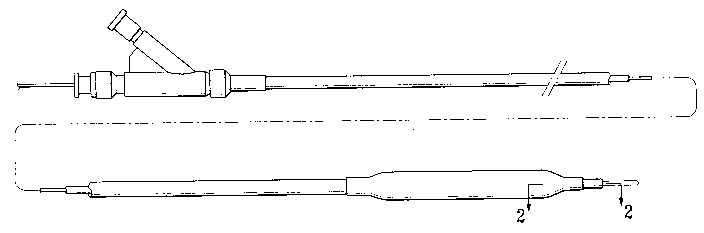
Fig. 1 is an elevational view of a balloon catheter which embodies
features of the invention.
Fig. 2 is an enlarged, longitudinal cross sectional view of the distal end of
the catheter shown in Fig. 1, taken along lines 2-2.
Fig. 3 is a cross sectional view of the catheter shown in Fig. 2, taken
along lines 3-3.
Fig. 4 is a cross sectional view of the catheter shown in Fig. 2, taken
along lines 4-4.
Fig. 5 is a cross sectional view of the catheter shown in Fig. 2, taken
along lines 5-5.
FIG. 6 is an enlarged, longitudinal cross sectional view of an alternate
embodiment of the catheter of the invention, havinc balloon shaft material
between the catheter shaft and tip member.
FIG. 7 is an enlarged, longitudinal cross sectional view of an alternate
CA 02391296 2002-05-09
WO 01/45783 PCT/US00/34372
4
embodiment of the catheter of the invention, having an intermediate member
between the catheter shaft and distal tip member.
FIG. 8 is an enlarged, longitudinal cross sectional view of an alternate
embodiment of the catheter of the invention, having a sheath located distally
adjacent to the distal end of the balloon distal shaft section and secured to
the
inner tubular member or tip member.
DETAILED DESCRIPTION OF THE INVENTION
Fig. 1 illustrates a balloon catheter 10 embodying features of the
invention, comprising an elongated catheter shaft 11 having a proximal shaft
section 12 and a distal shaft section 13, a tip member 14, an inflatable
balloon
on the distal catheter shaft section 13 having an interior 16, and an adapter
17 on the proximal catheter shaft section 12. In the embodiment illustrated in
Fig. 1, the catheter shaft 11 comprises an outer tubular member 18 having an
15 inflation lumen 19, and an inner tubular member 21 having a guidewire
receiving
lumen 22 disposed within the inflation lumen 18. Guidewire 23, illustrated in
Fig.
1 within guidewire receiving lumen 22, extends to port 24 in the distal end of
the
tip member 14. Balloon 15 has a working section 25, a proximal shaft section
26 disposed about and secured to a distal portion of the outer tubular member
18, and a distal shaft section 27.
As best illustrated in Fig. 2, showing an enlarged longitudinal cross
sectional view of a distal section of the catheter 10 shown in Fig. 1 taken
along
lines 2-2, the proximal end of the tip member 14 is spaced distally apart from
the
distal end of the inner tubular member 21, and thus is not in contact
therewith.
In the embodiment illustrated in Fig. 2, the distal end of the inner tubular
member 21 is disposed distally of the inflatable interior 16 of the balloon.
The
balloon distal shaft section 27 is disposed about a distal portion of the
inner
tubular member 21 and a proximal portion of the tip member 14. In a presently
preferred embodiment, the balloon distal shaft section 27 is secured to both
the
proximal portion of the inner tubular member 21 and the distal portion of the
tip
member 14, as for example, by fusion bonding. Alternatively, a sheath 40
located distally adjacent to the distal end of the balloon distal shaft
section 27
could be disposed about and secured to the inner tubular member 21 or tip
CA 02391296 2002-05-09
WO 01/45783 PCT/US00/34372
member 14 in place of the distal end of the balloon distal shaft section 27,
as
shown in Fig. 8.
As best illustrated in Fig. 2, tip member 14 has a lumen 28 in fluid
communication with guidewire receiving lumen 22. Figs. 3, 4 and 5 illustrate
5 transverse cross sectional views from the distal portion of the inner
tubular
member 21 to the proximal portion of the tip member 14 of the catheter 10,
taken along lines 3-3, 4-4, and 5-5, respectively. Tip member 14 is preferably
a
soft tip formed of a polymeric material which is softer than the material
forming
at least the distal portion of the inner tubular member 21, which is secured
to the
balloon distal shaft section 27. The tip member 14 illustrated in Figs. 2 and
5 is
formed of a single layer of a material or a blend of materials. However, the
tip
member 14 may be a multilayered or multisectioned member (not shown).
In the embodiment illustrated in Fig. 2, a gap 31 is between the distal end
of the inner tubular member 21 and the proximal end of the tip member 14. Gap
31 is defined between and in part by a transverse surface 33 of the distal end
of
the inner tubular member 21 and a transverse surface 34 of the proximal end of
the tip member 14. Balloon distal shaft section 27 is in surrounding relation
to
the distal end of the inner tubular member 21, gap 31, and the proximal end of
the tip member 14, so that the balloon distal shaft section 27 extends over
and
in part defines gap 31. As best illustrated in Fig. 4, showing transverse
cross
section of the balloon distal shaft section 27 at the gap 31, the inner
diameter of
the balloon distal shaft section is greater than the inner diameter of the tip
member 14.
In an alternative embodiment illustrated in Fig. 6, a portion 32 of the
balloon distal shaft section 27 extends between the distal end of the inner
tubular member 21 and the proximal end of the tip member 14. The portion 32
is in contact with the transverse surfaces 33 and 34, and has an inner surface
which defines a section of the guidewire receiving lumen 22. In the
embodiment illustrated in Fig. 6, the inner surface 35 of the portion 32 of
the
30 balloon distal shaft section 27 is substantially axially aligned with the
inner
surface 36 of the tip member 14. The phrase substantially axially aligned
should
be understood to mean that the portion 32 of the balloon distal shaft section
27
and the tip member 14 have the same inner diameter, or similar inner diameters
CA 02391296 2002-05-09
WO 01/45783 PCT/US00/34372
6
allowing for some slight variation in the inner surfaces 35/36. In an
alternative
embodiment, the portion 32 of the balloon distal shaft section 27 may fill
only a
portion of the space between the inner tubular member 21 and the tip member
14, so that an inner portion of the gap 31 remains (not shown).
In another embodiment illustrated in Fig. 7, intermediate member 41 is
secured to and extends between the distal end of the inner tubular member 21
and the proximal end of the tip member 14. In the embodiment illustrated, the
intermediate member 41 has a tubular shape with a length equal to the length
of
the space between the distal end of the inner tubular member 21 and the
proximal end of the tip member 14. In a presently preferred embodiment, the
intermediate member 41 is formed of a polymeric material which has a Shore
Durometer hardness which is lower than a Shore Durometer hardness of the
inner tubular member 21 and higher than that of the tip member 14. However,
the softness of the material may vary depending on the length of the bond
between the balloon distal shaft section 27 and the tip member 14, and the
desired use of the catheter 10. The intermediate member 41 can be made from
a variety of suitable materials, such as a polyamide including a polyether
block
amide, and polyethylene based adhesive polymers including ethylene-acrylic
acid copolymers such as PRIMACOR sold commercially by Dow Chemical Co.,
and polyurethanes such as PELLETHANE. The intermediate member 41 may
be configured similar to the portion 32 of the balloon distal shaft section
27, as
discussed above regarding the embodiment shown in Fig. 6. In the embodiment
illustrated in Fig. 7, the intermediate member 41 has an inner surface
substantially axially aligned with the inner surface 36 of the tip member 14
and
an inner surface of the inner tubular member 21, as discussed above regarding
the portion 32 of the balloon distal shaft section 27 shown in Fig. 6. The
intermediate member 41, and portion 32 of balloon distal shaft section 27,
preferably define annular lumens similar to those shown in Figs. 3-5.
The space is sufficiently long so that the polymeric materials forming the
inner tubular member 21 and tip member 14 do not flow into contact with one
another during fusion bonding of the balloon distal shaft section 27 thereto.
The
length of the space (i.e., the length of gap 31, or portion 32, or
intermediate
member 41 ) between the distal end of the inner tubular member 21 and the
CA 02391296 2002-05-09
WO 01/45783 PCT/US00/34372
7
proximal end of the tip member 14 may vary depending on the desired catheter
performance, the length of the balloon distal shaft section 27 and tip member
14, and the method used to bond to tip member. The length of the space is
typically about 0.05 mm to about 0.75 mm, preferably about 0.05 mm to about
0.5 mm, most preferably about 0.1 mm to about 0.3 mm. In a presently
preferred embodiment, the balloon distal shaft section 27 is about 1 to about
3
mm, preferably about 1.8 to about 2.2 mm. The tip member 14 is typically about
1 to about 5 mm, preferably about 2 to about 3 mm. In the embodiment
illustrated in Figs. 2, 6 and 7, the tip member 14 proximal end is distal to
the
longitudinal center of the balloon distal shaft section 27. However, in
alternative
embodiments, the tip member 14 proximal end may be located in various other
locations along the length of the balloon distal shaft section 27 (not shown).
The catheter shaft.will generally have the dimensions of conventional
dilatation or stent deploying catheters. For coronary use, the length of the
catheter 10 may be about 90 cm to about 150 cm, and is typically about 145 cm.
The outer tubular member 18 has a length of about 15 cm to about 50 cm, an
outer diameter (OD) of about .03 inch to about .05 inch, and an inner diameter
(ID) of about .031 inch. The inner tubular member 20 has a length of about 15
cm to about 100 cm, an OD of about .024 in and an ID of about .017 in. The
inner and outer tubular members may taper in the distal section to a smaller
OD
or ID. Although not illustrated, the catheter shaft inner tubular member, or
outer
tubular member, may be made of multiple shaft sections joined together.
A method of forming a distal tip of a balloon catheter comprises
positioning a proximal end of a tip member and a distal end of a catheter
shaft
within a lumen of a balloon distal shaft section, so that the proximal end of
the
tip member is distally apart from the distal end of the catheter shaft. The
balloon
distal shaft section is fusion bonded to the catheter shaft and the tip member
by
applying heat to at least a portion of the balloon distal shaft section, to
form a
balloon catheter distal tip having the tip member proximal end fusion bonded
to
the balloon distal shaft section and spaced dl stally apart from the distal
end of
the catheter shaft. Typically a mandrel is positioned within the inner tubular
member lumen 22 and the tip member lumen 28 bE~fore the fusion bonding. In a
presently preferred embodiment, a laser is used to heat the material for
fusion
CA 02391296 2002-05-09
WO 01/45783 PCT/US00/34372
8
bonding, and laser parameters such as focal length and power are selected to
provide the desired heat spread. The focal length is typically about 2.6 to
about
3.25 inch, and the power is typically about 125 mw to about 170 mw for a YAG
(yttrium aluminum garnet) type laser. In one embodiment, the balloon distal
shaft section is heated so that the balloon material flows into at least a
part of
the space between the proximal end of the tip member and the distal end of the
catheter shaft. Alternatively, a removable spacer, configured to fit in the
space
between the inner tubular member and the tip member, may be disposed
between the distal end of the inner tubular member 21 and the proximal end of
the tip member 14 during fusion bonding, or the fusion bonding heat may be
controlled, such that the balloon material does not flow within the space
between
the inner tubular member 21 and the tip member 14.
In the embodiments illustrated in Figs. 2, 6 and 7, the outer surface of the
balloon distal shaft section tapers distally to a smaller outer diameter. In
one
embodiment, the taper in the balloon distal shaft section 27 is formed during
fusion bonding as the balloon polymeric material is heated and flows distally.
Although not shown in the figures, the portion 32 of the balloon distal shaft
section 27 may have a dip, i.e., a concave surface, formed as the balloon
polymeric material flows into the space between the inner tubular member 27
and the tip member 14.
To the extent not discussed above, the various catheter components may
be formed of conventional materials. The inner tubular member may be formed
of a variety of conventional catheter shaft materials, including PEBAX, Nylon,
and high density polyethylene, used atone or in blends or multilayered
members.
In a presently preferred embodiment, the inner tubular member includes at
least
a layer of PEBAX having a Shore Durometer hardness of about 60D to about
72D.
While the present invention is described herein in terms of certain
preferred embodiments, those skilled in the art will recognize that various
modifications and improvements may be made to the invention without departing
from the scope thereof. For example, although discussed primarily in terms of
a
catheter having an inner and outer tubular member, it would be obvious to one
of ordinary skill in the art that the catheter shaft may alternatively have a
dual
CA 02391296 2002-05-09
WO 01/45783 PCT/US00/34372
9
lumen shaft design. Moreover, although individual features of one embodiment
of the invention may be discussed herein or shown in the drawings of the one
embodiment and not in other embodiments, it should be apparent that individual
features of one embodiment may be combined with one or more features of
another embodiment or features from a plurality of embodiments.