Note : Les descriptions sont présentées dans la langue officielle dans laquelle elles ont été soumises.
CA 02391788 2002-06-25
q,011
IP 1333
1
SUSPENSION ROPE WEAR DETECTOR
BACKGROUND OF THE INVENTION
The present invention relates generally to elevator
suspension ropes and, in particular, to wear detectors for
polyurethane coated suspension ropes.
Steel wire ropes are well known. Steel wire ropes consist
of metal strands braided or twisted together to form a
rope. Steel wire suspension ropes are used as stationary
and as running ropes for many different purposes. Such
ropes have the advantage of being inexpensive, durable, and
flame retardant. One common use for suspension ropes is in
elevator applications. A conventional traction type
elevator application includes a cab mounted in a car frame,
a counterweight attached to the car frame via the
suspension rope, and a machine driving a traction sheave
that is engaged with the rope. As the machine turns the
sheave, friction forces between the grooved surface of the
sheave and the rope move the rope and thereby cause the car
frame and counterweight to raise and lower. A control
device is included to monitor and control the operation of
the machine and the various mechanical components of the
elevator application.
Used as either stationary or running ropes, steel ropes can
support heavy loads. In the case of running ropes, this
tensile loading is complemented by flexural loading that
reduces their service lifetime due to the number of load
ranges in which they operate. The coefficient of friction
CA 02391788 2002-06-25
IP 1333
2
or frictional value between the metal drive pulley and the
steel rope is generally so low that the frictional value
must be increased by different measures. These measures can
include special groove shapes or special groove linings in
the drive pulley, or through an increase of the loop angle.
In addition, the steel rope acts as a sound bridge between
the drive and the elevator car, which entails a reduction
in travelling comfort. These running steel wire ropes,
moreover, do not last forever, as mechanical wear of the
ropes is an obvious consequence of their continual
operation. Due to increasing stresses, friction and wear,
wire fractures gradually occur in the bending zones. These
fractures occur due to a combination of different loads on
the elevator ropes, low tension stresses, and high
pressures at high cycle rates. The safety of the steel
wire rope condition is monitored in order to detect an
operationally critical state of their wear, in advance of
failure of the ropes. This is known in the art as
controllable wire rope failure, which means that the
danger-free remaining period of use can be read from an
outward degree of wear of the steel wire rope. Once a
predetermined amount of wear has occurred, the steel wire
rope is replaced. In addition, steel wire ropes require
lubrication. The steel wire ropes are treated with an oil
lubrication that ultimately can be deposited on the
elevator car frame and equipment.
One known method of solving the friction, travelling
comfort, and wear resistance problems is to construct ropes
of synthetic fiber. Synthetic fiber ropes, however, are
not always desirable because they are relatively expensive
compared to a steel rope. Another known method of solving
the friction, noise, and wear resistance problems is to
provide a coating, or sheath. The sheath allows smoother
and quieter elevator operation in that there is less
I JI I
CA 02391788 2002-06-25
IP 1333
3
friction when the rope moves across the pulleys and sheaves
as compared to the metal-to-metal contact with a steel rope
that does not have a sheath. The sheath is typically
formed from a synthetic plastic material, such as
polyurethane, and its purpose is to provide wear resistance
for the wire rope. Another benefit is that the sheath
provides a sacrificial wear material so the metallic drive
pulley wear is at least reduced and at best eliminated..
Once the sheath has sustained a predetermined amount of
wear, like conventional steel wire ropes, the rope is
replaced.
The current means of wear detection of polyurethane type
covers is to visually inspect on a periodic basis for cover
wear or damage. This is a time-intensive operation that
requires the elevator to be placed out of service while
maintenance personnel perform the visual inspection of the
entire suspension rope. It is desirable to reduce both the
amount of time and the manpower necessary to determine the
wear or damage of the polyurethane cover of the suspension
rope. It is also desirable to monitor the wear of the
polyurethane sheath and to provide a notification to the
operator of an elevator as soon as abnormal or increased
wear on a suspension rope is detected.
It is an object of this invention, therefore, to detect, by
either electrical or optical means, the wear on the rope
sheath in order to determine when the rope needs
replacement. It another object of this invention to provide
an inexpensive means for determining wear or damage on a
suspension rope and to be able to determine the amount of
wear or damage remotely.
SUMMARY OF THE INVENTION
The present invention concerns an apparatus for detecting
I I I I RI
CA 02391788 2002-06-25
IP 1333
4
wear in suspension ropes with polyurethane sheaths when
used with an elevator assembly.
In a preferred embodiment, the present invention
contemplates detecting wear of the non-conductive
polyurethane sheath by providing a sensing circuit with any
grounded object such as a drive sheave or an idler sheave.
When the electrically conductive strands of the rope make
contact with the drive sheave or idler sheave through the
worn non-conductive polyurethane cover, the sensing circuit
signals the control device to take the car out of service
once the rope becomes electrically grounded.
In an alternative embodiment, the present invention
contemplates detecting wear of the non-conductive
polyurethane sheath by providing a proximity sensor that
contacts the polyurethane sheath and actively measures the
sheath thickness as a distance to the rope strands. The
sensor signals the elevator control device to take the car
out of service once a predetermined cover thickness wear
has occurred.
In another alternative embodiment, the present invention
contemplates detecting wear of the non-conductive
polyurethane sheath by providing layers of different
colors. The polyurethane sheath changes color when an outer
layer of one color is worn away to expose an inner layer of
another color indicating that predetermined wear has
occurred. An optical sensor is then utilized to detect the
inner layer color and signal the control device to take the
car out of service.
In each of the above-described embodiments, the present
invention provides a sensor means for the active monitoring
of the wear of the rope polyurethane sheath at all times.
The present invention provides multiple means for remotely
CA 02391788 2010-04-30
monitoring the rope polyurethane cover wear, with each
means utilizing low cost technology components. The present
invention is also able to detect both complete and partial
wear of the rope polyurethane cover. In addition, the
5 present invention allows the rope polyurethane cover wear
to be visually inspected without the use of measurement
tools.
In another aspect, the present invention provides a
suspension rope wear detector (2, 32, 52) in an elevator
comprising: a suspension rope (4, 43, 54) and a sheath (8,
38, 58), the suspension rope (4, 43, 54) being formed from
a plurality of load bearing strands (6, 36, 56) extending
longitudinally to form the suspension rope (4, 43, 54),
said strands (6, 36, 56) being formed of a first material
and the sheath (8, 38, 58) covering said strands (6, 36,
56), said sheath (8, 38, 58) being formed of a second
material; and a sensor means for sensing wear at a surface
(8a, 38a, 58a) of said sheath (8, 38, 58) and generating a
wear indication output signal (22, 42, 62) upon sensing a
characteristic feature of the suspension rope representing
a predetermined amount of wear (8b, 38b, 58b) of said
sheath (8, 38, 58); characterized in that said
characteristic feature being one of an electrical contact
of at least one of said strands (6) with a member (10)
contacting said sheath surface (8a, 8b),a distance between
said sheath surface (38a, 38b) and at least one of said
strands (36), and a change in color of said sheath surface
(58a, 58b).
In yet another aspect, the present invention provides an
elevator suspension rope comprising: a plurality of load
bearing strands extending longitudinally to form a
suspension rope, said strands being formed of an
CA 02391788 2010-04-30
5a
electrically conductive material; a sheath covering said
strands, said sheath being formed of an electrically
insulating material; and a sensor means for sensing wear at
a surface of said sheath and generating a wear indication
output signal upon sensing a predetermined amount of wear of
said sheath, wherein said sensor means includes an
electrically conductive member abutting said surface and a
power supply connected between said strands and the member,
said wear indication output signal being current flow
between at least one of said strands and the conductive
member when said surface of the sheath is worn away to
expose said at least one strand and permit contact between
said at least one strand and the member.
In yet a further aspect, the present invention provides an
elevator suspension rope comprising: a plurality of load
bearing strands extending longitudinally to form a
suspension rope, said strands being formed of an
electrically conductive material; a sheath covering said
strands, said sheath being formed of an electrically
insulating material; and a sensor means for sensing wear
at a surface of said sheath and generating a wear
indication output signal upon sensing a predetermined
amount of wear of said sheath, wherein said sensor means
includes a proximity sensor contacting said surface, said
wear indication output signal being generated by said
proximity sensor when said surface of the sheath is worn
away to move said proximity sensor within a predetermined
distance of at least one of said strands.
In yet another further aspect, the present invention
provides an elevator suspension rope comprising: a
plurality of load bearing strands extending longitudinally
to form a suspension rope, said strands being formed of an
CA 02391788 2010-04-30
5b
electrically conductive material; a sheath covering said strands,
said sheath being formed of an electrically insulating material;
and a sensor means for sensing wear at a surface of said sheath
and generating a wear indication output signal upon sensing a
predetermined amount of wear of said sheath, wherein said sensor
means includes an optical sensor positioned adjacent said
surface, the sheath having an outer layer of one color including
said surface and at least one inner layer of a second color, said
wear indication output signal being generated by said optical
sensor when said surface of the sheath is worn away to expose
said at least one inner layer.
DESCRIPTION OF THE DRAWINGS
The above, as well as other advantages of the present invention,
will become readily apparent to those skilled in the art from the
following detailed description of a preferred embodiment when
considered in the light of the accompanying drawings in which:
Figs. la and lb are cross-sectional views of a suspension rope
wear detector in accordance with the present invention;
Figs. 2a and 2b are cross-sectional views of a first alternative
embodiment of a suspension rope wear detector in accordance with
the present invention; and
Figs. 3a and 3b are cross-sectional views of a second alternative
embodiment of a suspension rope wear detector in accordance with
the present invention.
DESCRIPTION OF THE PREFERRED EMBODIMENTS
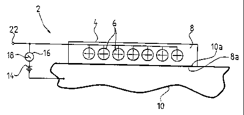
Referring now to Fig. la, a suspension rope wear detector is
indicated generally at 2. A wire rope 4 is shown in cross
section as including a plurality of load supporting wire
members or strands 6 that extend longitudinally a length of
the rope. The wire members 6 are preferably
1; 'I~ 1,1 11 1
CA 02391788 2002-06-25
100",
IP 1333
6
constructed of an electrically conductive material and
typically are wound from a plurality of individual wires.
An electrically insulating sheath 8 encases the members 6
of the wire rope 4. The sheath 8 is preferably constructed
of a synthetic plastic material, such as polyurethane. The
wire rope 4 is in contact with an electrically grounded
member 10. The grounded member 10 may be a traction
sheave, an idler sheave, or any other member that is formed
of electrically conductive material. Although the rope 4
is depicted as being belt-like, with a planar surface 8a
engaging a facing planar surface 10a of the grounded member
10, other rope and pulley forms are known such as a
generally circular cross section rope engaging a grooved
pulley. The rope 4 is shown in a usable condition wherein
the sheath 8 electrically insulates the wire members 6 from
the grounded member 10.
Referring now to Fig. lb, the rope 4 is shown with the
sheath 8 in a worn condition wherein the surface 8a shown
in Fig. la is worn away down to an inner surface 8b. One
or more of the wire members 6 is exposed through the
surface 8b to contact the grounded member surface 10a at a
contact point 12. The wire members 6 and the grounded
member 10 are electrically connected at the contact points
12. The wear detector 2 includes a sensor means having a
power supply 14 and an indicator 16 electrically connected
in series between the wire members 6 and the grounded
member 10. In Fig. la, there is an open circuit due to the
insulating properties of the sheath 8 such that no current
flows from the power supply 14 through the indicator 16
which provides a first display 18 indicating that the rope
4 can remain in service. In Fig. 1b, there is a closed
circuit at contact points 12 due to the wear of the sheath
8 permitting current flow through the indicator 16 which
provides a second display 20 indicating that the rope 4
CA 02391788 2002-06-25
IP 1333
7
should be removed from service. A signal terminal 22 of
the sensor means can be connected to an elevator control
device (not shown) to generate an output signal in response
to which the control device then takes the appropriate
action with respect to the indicated condition, including
ceasing elevator operation when the output signal
represents the second display 20 wear indication.
A broken individual wire of a wire member 6 can perforate
the insulating sheath 8. In this case the individual wire
contacts the grounded member surface 10a of the sheave.
When the sheave is rotating the contact of the individual
wire is interrupted after a certain time depending on the
travel speed of the rope 4 and the diameter of the sheave.
The wear detector 2 is able to evaluate the number of
broken individual wires.
Referring now to Fig. 2a, an alternate embodiment
suspension rope wear detector is indicated generally at 32.
A wire rope 34 is shown that contains a plurality of wire
members or strands 36. The wire members 36 are preferably
constructed of a metal material. A sheath 38 encases the
members 36 of the wire rope 34. The sheath 38 is preferably
constructed of a synthetic plastic material, such as
polyurethane. A sensor means is provided in the form of a
proximity sensor 40. A surface 38a of the wire rope 34
abuts the proximity sensor 40 that measures the thickness
of the sheath 38 as a distance between the sensor and the
members 36. The proximity sensor 40 generates an output
signal at a signal output 42 that can be connected to an
elevator control device (not shown.) in response to which
the control device then takes the appropriate action with
respect to the indicated condition.
Referring now to Fig. 2b, the wire rope 34 is shown with
CA 02391788 2002-06-25
IP 1333
8
the sheath 38 in a worn condition wherein the surface 38a
shown in Fig. 2a is worn away down to a new surface 38b.
Now the wire members 36 are closer to the proximity sensor
40 which generates a wear indication output signal to the
control device once a predetermined amount of wear on
sheath 38 has occurred. The control device then takes the
appropriate action with respect to the indicated condition,
most likely to cease elevator operation.
Referring now to Fig. 3a, a suspension rope wear detector
is indicated generally at 52. A suspension rope 54 is
shown that contains a plurality of members or strands 56
that can be formed of an electrically conducting material
or a synthetic material. The members 56 are preferably
constructed of an electrically conductive material. A
sheath 58 encases the members 56 of the rope 54. The
sheath 58 is preferably constructed of a synthetic plastic
material, such as polyurethane, and has a plurality of
colored layers, each of which corresponds to an amount of
wear on the sheath. For example, a surface 58a displays a
first color of an outer layer 58c and a surface 58b
displays a second color of an inner layer 58d. Although
the layers 58c and 58d are shown as extending in a single
plane, they could extend any distance about the periphery
of the rope 54 including completely around it.
The surface 58a of the rope 54 passes by an optical sensor
60, which detects the contrasting first color of the sheath
58 that represents a first amount of acceptable wear of the
sheath 58. The optical sensor 60 has a signal output 62
for connection to an elevator control device (not shown.).
Thus, a first output signal generated at the output 62
indicates to the control device that the rope 54 can remain
in service.
I 11 I 1
CA 02391788 2002-06-25
IP 1333
9
Referring now to Fig. 3b, the wire rope 54 is shown with
the sheath 58 in a worn condition whereby the surface 58b
is exposed. The optical sensor 60 senses the change from
the first color of the surface 58a to the second color of
the surface 58b and generates a second signal, wear
indication output signal, at the output 62 indicating that
a predetermined amount of wear has taken place whereby the
rope 54 should be taken out of service. The elevator
control device then can take the appropriate action, most
likely to cease elevator operation.
In summary, the suspension ropes 4, 34 and 54 are formed
from at least one load bearing strand covered by sheath. A
sensor means is provided for monitoring a surface of the
sheath and generating a wear indication output signal
representing at least one predetermined wear condition of
the rope and includes an output adapted to be connected to
an elevator control device for transmitting the wear
indication output signal. With respect to the rope 4, a
sensor means 14, 16 provides an electrical circuit whereby
contact between the electrically conducting strands 6 and
an electrically conducting member 10 generates the wear
indication output signal. With respect to the rope 34, a
proximity sensor means 40 senses a distance between the
strands 36 and a surface of the sheath 38 to generate the
wear indication output signal. With respect to the rope
54, an optical sensor means 60 senses a color change in a
surface of the sheath 58 to generate the wear indication
output signal. As described with respect to the cable 4,
the cables 34 and 54 can be formed in any suitable
configuration such as a generally circular cross section
rope wherein the strands are twisted about a central core
strand.
In accordance with the provisions of the patent statutes,
CA 02391788 2002-06-25
IP 1333
the present invention has been described in what is
considered to represent its preferred embodiment. However,
it should be noted that the invention can be practiced
otherwise than as specifically illustrated and described
5 without departing from its spirit or scope.