Note : Les descriptions sont présentées dans la langue officielle dans laquelle elles ont été soumises.
CA 02391838 2002-06-27
R n ~
VTX 2 0003
SYMMETRICAb GASRET FOR A PIPE JOINT
WITH INCREASED SURFACE CONTACT
BACKGROUND OF THE LNVENTION
The present invention relates generally to flexible
fluid-type seals for pipe joints. More particularly, the
invention relates to a gasket adapted for sealing bell-and
spigot type pipe joints.
The gasket disclosed herein is particularly adapted
for use in the field of sewer pipe assemblies. However, it
should be appreciated that the gasket design disclosed could
be adapted for use in many other types of pipe joints as
well.
Sewer pipe assemblies are generally made of
plastic, polyethylene, metal, concrete, or other suitable
materials: These are fabricated in many configurations and
sizes to meet specific requirements and users' preferences.
In many such pipe assemblies, grooves are formed or recesses
are provided in ribbed or corrugated types of pipe. Although
a spigot, i.e., a male groove, is the dominant method
employed for manufacturing sewer pipes, it is also possible
that a formed groove in the bell, i.e", female pipe, can be
utilized.
Some gaskets are integrally installed at the
factory during fabrication of the sewer pipes while others
are simply applied at the job site. For very large diameter
concrete pipes, such as in storm and sanitary sewer systems,
field installation of the gaskets is generally considered
necessary:
Historically, piping systems have utilized
polymeric gasket elements to provide resilient seals under
CA 02391838 2002-06-27
4 , f
if i
-
various operating conditions. These include no internal
pressure, no external pressure, working internal pressure,
high external pressure, internal vacuum, or any combination
of these. In each case, the gasket must maintain its ability
to seal when quick changes occur in the pressures imposed on
the gasket.
O-ring type gaskets have frequently been employed
on large diameter pipe joints. The O-ring is typically
mounted on the spigot, and the spigot is then pushed into the
l0 bell causing the O-ring to roll further onto the spigot until
it reaches roughly the center of the pipe connection. Dirty
or uneven surfaces, poor or improperly applied lubricants,
misaligned pipes, and: excessive force may cause the O-ring to
distort non-uniformly, resulting in a weak seal, or even in
a void through which fluids can flow. Some spigots include
a circumferential groove or a single or a double offset
shoulder to keep the O-ring from rolling as the pipes are
interconnected. However, the diameter of the O-ring and its
radial cross-section are usually greater than the depth of
the groove or shoulder and the ring may still roll over the
inside edge of the groove, become snagged or shear off
segments of the O-ring as the spigot enters the bell.
Various gasket configurations have been used or
suggested for overcoming these deficiencies. In order to
provide self-alignment of the gasket, various gasket profiles
have been developed. Typically, however, it is essential
that the gasket be placed on the spigot in a desired
orientation. That is, the gasket functions properly onlyv
when it is installed in a particular direction and cannot
function if installed in a reverse or backwards manner. This
has made it necessary for identification marks to be placed
on the surface of the gasket for the purpose of
distinguishing the front, or functional side, of the gasket
profile from the back, or non-functional side. These
stripes, printing, or color coding identifiers then become
critical to the success or failure of the sealing system.
Sealing rings are known for sealing against fluid
flow in both high and low pressure conditions in either
CA 02391838 2002-06-27
,. ~ c . r
- 3 -
direction. However, these sealing rings are not symmetrical
and, therefore, can be installed incorrectly so that they
will not seal properly,.
There are symmetrical gaskets known for pipe
joints. In commonly assigned U.S. Patent No. 5,687,976, the
entire contents of which are incorporated herein by
reference, there is disclosed a symmetrical pipe joint gasket
which includes an annular gasket body formed of a resilient
material. The gasket includes a projection which extends
radially away from the gasket body and an annular bore which
is spaced away from the projection and which extends in the
gasket body. Both the projection and the annular bore are
located so that they are bisected by the centerline of the
gasket profile. The gasket is insensitive to axial
orientation and is able to react to pressure fluctuations.
It will be recognized that the gaskets in accordance with the
present invention have many of the attendant advantages of
those disclosed in U.S. Patent No. 5,687,976.
Certain problems exist in pipe manufacturing
processes that result in conditions which provide ineffective
sealing surfaces on the portion of the pipe which contacts
the gasket. Such surface conditions include, pitting,
crazing, raised bumps, waviness, flow marks, indentations,
undispersed ingredients that come to the surface, and other
such conditions where the pipe surfaces are not as smooth and
consistent as desired. Such defects have the ability to
cause a weak seal or a failure: in the pipe joint, especially
under conditions of internal pressures, external pressures,
and internal vacuums. The failures occur since a pathway for
liquid or air is created over, under, or around these surface
imperfections.
Typically, many pipe joints are disqualified
because of these results. Although the pipe may be otherwise
fully acceptable, a minor imperfection on the sealing surface
where the gasket contacts the pipe may result in a failure.
If the gasket chosen cannot overcome this type of operating
challenge; increased costs to the pips producer, contractor,
and ultimately the property owner, result.
CA 02391838 2002-06-27
c ,
- 4 -
Since minor surface conditions will arise in some
of the many, many miles of pipe produced each year, a gasket
sealing system which can overcome such defects would be of
assistance to manufacturers and users of such piping
installations by providing additional confidence and
reliability and preventing major problems in the field.
Accordingly, it has been considered desirable to
develop a new and improved gasket and pipe joint design which
would overcome the foregoing difficulties and others while
ZO providing increased seal efficiency under higher operating
pressures and other benefits.
SUMMARY OF THE INVENTION
According to the present invention, a gasket and
pipe joint employing the same is provided having increased
surface contact area and force.
In accordance with a first aspect of the present
invention, a pipe joint comprises an outer pipe and an inner
pipe inserted therein, wherein an annular groove is formed on
one of the facing surfaces of the outer. and inner pipes. A
gasket positioned within the annular .groove is adapted to
provide a seal between the inner and outer pipes. The gasket
comprises an annular gasket body formed of a resilient
material and is symmetric about a centerline. The gasket
body includes a base adapted to sealingly engage the groove,
and has first and second projections or protrusions which run
longitudinally along the gasket body and extend away
therefrom. The first and second projections are located on
opposed sides of the centerline. An annular bore, extending
interiorly within the gasket body, compr9.ses a central region
bridging first and second spaced apart lobes, the bore being
located in the gasket body such that it is bisected by the
centerline thereof.
Ln a second aspect, a non-directional gasket which
is insensitive to axial gasket orientation includes an
annular gasket body which is formed of a resilient material,
and which has an axial centerline and a base adapted to
sealingly engage an annular groove on a pipe. First and
CA 02391838 2002-06-27
' ~ . ,
- 5 -
second protrusions are symmetrically spaced apart about the
centerline, and an annular bore extends in the gasket body.
The bore includes a central region bridging first and second
spaced apart lobes and is bisected by the centerline.
In a third aspect, a gasket for sealing an annular
space in a bell-and-spigot pipe joint is provided which can
be installed in an associated pipe joint. in either direction
along a longitudinal axis of the associated pipe joint. The
gasket includes an annular elastomeric web having an inner
l0 peripheral surface formed to sealingly engage an outer
periphery of an associated spigot. The web is symmetric
about a centerline, and first and second elastomeric
protrusions are symmetrically contraposed thereabout. The
protrusions project outward from the web and are deflectable
to engage an inner periphery of an associated bell.
In a fourth aspect of the present invention, a pipe
joint which can accommodate surface defects in a joined
sealing surface includes an outer pipe and an inner pipe
inserted into the outer pipe, wherein one of the pipes
comprises an annular groove. A gasket positioned within the
annular groove is adapted to provide a seal between the outer
pipe and the inner pipe. The gasket includes an annular
gasket body formed of a resilient material and is
transversely symmetrical about a centerline. The gasket
includes a base portion adapted to sealingly engage the
groove. First and second projections run along the gasket
body and extend away therefrom the first and second
projections being symmetrically spaced apart about the
centerline and defining a recess therebetween. The gasket
body is deformable to increase a surface contact area when
the inner pipe is inserted into the outer pipe. An annular
bore extends in the gasket body: The bore is adapted to
equalize pressure in transverse fashion across the surface
contact area when the inner pipe is inserted into the outer
pipe.
In a fifth aspect, an improved method is provided
for producing an annular gasket of a type for sealing a gap
between an inner pipe and an outer pipe, wherein one of the
CA 02391838 2002-06-27
9 , T
- 6 -
pipes carries a gasket within an annular groove. The gasket
comprises a first end engaging the groove and a second end
disposed opposite the first end facing an aligned sealing
surface of the other of the inner and outer pipes. The
method includes producing an elongate gasket, formed from an
elastically compressible material, as by molding or
extrusion, and attaching opposite ends of the gasket. At the
same time that the elongate gasket is being produced, first
and second projections are provided running along the gasket
body and extending away therefrom, and the first and second
projections being symmetrically spaced apart about an axial
centerline of the gasket. Also produced at the same time the
gasket body is being produced is an annular bore extending in
the gasket body, the bore comprising a central region
bridging first and second spaced apart lobes, the bore being
located in the gasket body such that it is bisected by the
centerline.
In a sixth aspect, a method for increasing the
surface contact area of a gasket sealing a space between an
inner pipe segment and an outer pipe segment adapted to
receive the inner pipe comprises forming; at the same time
the gasket is formed, first and second projections running
along the gasket and extending radially therefrom. The first
and second projections are symmetrically spaced apart about
a centerline of the gasket. At the same time the gasket is
formed, an annular bore is formed in the gasket. The bore
comprises a central region bridging first and second spaced
apart lobes, the bore being located within the gasket body
such that it is bisected by the centerline. An annular
groove is formed on onej of the inner and outer pipes and the
gasket is installed therein such that it is positioned within
the annular groove. The inner pipe is then inserted into the
outer pipe'to compress the gasket and to provide a sealing
pressure between the inner and outer pipes.
BRIEF DESCRIPTION OF THE DRAWINGS
The invention may take form in certain structures
and parts, several preferred embodiments of which will be
CA 02391838 2002-06-27
r
-
described in detail in this specification and illustrated in
the accompanying drawings; wherein:
FIGURE 1 is a perspective sectional view of a
gasket and a pipe joint according to a ffirst embodiment of
the present invention;
FIGURE 2A is an enlarged cross-sectional view of
the gasket of FIGURE 1;
FIGURE 2B is a cross-sectional view of the pipes in
the pipe joint of FIGURE 1;
FIGURES 3A-3C illustrate the manner of assembling
the pipe joint of FIGURE 1;
FIGURES 4-16 are cross-sectional views of some
exemplary further embodiments of the present invention;
FIGURE 17 is a cross-sectional view of a gasket in
a pipe joint according to yet another embodiment of the
present invention; and
FIGURE 18 is a cross-sectional view of a gasket
according to still another embodiment of the present
invention in a pipe joint utilizing a supplemental gasket.
DETAILED DESCRIPTION OF THE PREFERRED EMBODIMENTS
Referring now to the drawings, wherein the showings
are for purposes of illustrating several preferred
embodiments of the invention only and not for purposes of
limiting same, and further wherein like reference numerals
and characters are used to denote like components throughout
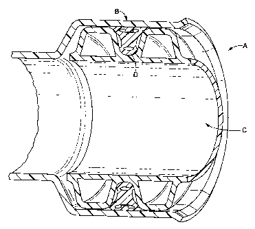
the several views, FIGURE 1 shows a pipe joint A including a
first, female pipe B (bell), a second, male pipe C (spigot),
and a gasket D meant for sealing between the two pipes.
Gasket D is shown in its compressed configuration. While the
pipe joint is illustrated to be of the bell-and-spigot type
which is generally used in sewer pipe assemblies, it should
be appreciated by those of average skill in the art that the
gasket illustrated herein could be used in other types of
sealing environments as well.
With reference now to FIGURE. 2A, the gasket D,
shown in the uncompressed state, comprises an elongate
annular gasket body or web 10. An axial centerline 12
CA 02391838 2002-06-27
bisects the gasket profile and axial extension of the
centerline defines a plane of transverse symmetry of the
gasket thereabout.
The gasket body includes a base portion 14 and an
oppositely disposed upper (in the orientation shown) portion
16 having two protrusions 18 and 20 symmetrically disposed
about centerline 12. The protrusions run longitudinally
along the length of the gasket body 10 and extend outwardly,
i.e:, generally in the direction of t:he sealing force. A
recess 22 is defined between the protrusions.
As used herein, the-term "base portion" is intended
to refer generally to the end of the gasket body which is
intended to engage a complimentary depression in a pipe
section (preferably in the male or spigot portion) forming a
pipe joint, i.e., the proximal end of the annular gasket.
The term "upper portion" is intended to refer to generally to
the opposite end, which in operation is disposed toward an
opposing surface of a pipe segment (preferably the female or
bell portion) forming a pipe joint, i.e., the distal end of
the annular gasket. The distinction, being made solely for
ease of exposition, is general with there being no intention
of defining a clear line of demarcation between the base and
upper portions, such portions being integrally formed with
each other.
The upper portion 16 also comprises transversely
extending first and second wings or lips 24 and 26. The
first and second lips are symmetrically located about the
centerline 12.
Extending axially through the upper portion 16 is
a channel or bore 30. The axial channel 30 comprises a
central region 32 bridging first and second transversely
spaced apart lobes 34 and 36. The axial channel 30 is
symmetrical about the axial centerline 12. The lobes 34 and
36 extend toward the spaced apart protrusions 18 and 20,
respectively, from within the gasket body 10.
Extending axially through the base 14 is an
optional aperture 38, which is bisected by the axial
centerline 12. In this embodiment, the aperture is
CA 02391838 2002-06-27
f . i
- 9 -
illustrated to be elliptical in cross-sectional shape,
although circular and other geometrical cross-sectional
shapes are also contemplated.
The gasket body l0 is manufactured from a suitable
conventional elastomeric material in a conventional manner,
such as by extrusion, molding, and the like. The two ends of
the gasket body are then secured together to form a toroidal
shape as is well known in the art.
The material forming the gasket may be, for
example, a synthetic or natural elastomeric or rubber
material. Exemplary elastomeric materials which may be used
in making the gasket include, but are not limited to,
polyisoprene, neoprene, butadiene-acry7lonitrile copolymers,
ethylene-butadiene block copolymers, ethylene-propylene based
copolymers, natural rubber, polychloroprene rubber,
polyisoprene-isobutylene copolymers, silicone rubber;
styrene-acrylonitrile copolymers, styrene-butadiene
copolymers, styrene-malefic anhydride copolymers, and so
forth .
A series of compression points are located on the
gasket body l0. These comprise a first compression point 40
located at the apex of the first protrusion 18, a second
compression point 42 located at the apex of the second
protrusion 20, a third compression point 44 located at the
lip 24, a fourth compression 46 point located at the lip 26,
and a fifth compression point 48 located at the lowest point
of the base 14. A pair of optional sealing lips 13 and 15 on
opposite sides of base portion 14 provide additional contact
points to effect sealing.
With reference now to FIGURE 2B, the gasket is
meant to be used between the first pipe :B and the second pipe
C. The first pipe; or outer pipe, includes a bell 50 having
an internal wall surface 52. The second pipe, or inner pipe,
includes an external wall surface 60 and an internal wall
surface 62 between which is defined a. groove 64 which is
generally U-shaped in cross-section.
FIGURES 3A-3C illustrate a manner of assembling the
pipe joint A in accordance with the present invention. The
CA 02391838 2002-06-27
- 30 -
gasket D is placed in the groove 64 as illustrated in FIGURE
3A. The groove 64 and the gasket D are sized such that once
the gasket is so located, even in an uncompressed state, the
third, fourth, and fifth compression points 44, 46, and 48
are in contact with the respective wall surfaces of the inner
or second pipe C that define the U-shaped groove 64.
As illustrated in FIGURE 3B, the second pipe C is
inserted into the first pipe 8 in the direction 7o indicated.
The sealing elements of the gasket are forced against the
pipe surfaces during installation. The dual protrusions Zs
and 20 compress or deform to create an increased surface
contact area when they are displaced in cooperation with the
bore 30 to conform to he annular space of the joint area.
As the second pipe C is inserted, the first
protrusion 18 pushes against the inner surface 52 of the
first pipe B, creating a mechanical force thereagainst. Upon
further insertion, the second protrusion 20 also pushes
against the inner surface 52 of the first pipe B.
The increased contact pressure or force provided by
the gasket of the present invention is the result of a
pressure transference from one side of the bore 30 to the
other, forcing the gasket to move against the surfaces as the
coupling or installation load increases. As the second pipe
C is fully inserted into the first pipe B (FIGURE 3C), the
pressure substantially equalizes across the gasket and the
increased force exerted in opposing directions is realized.
This effect, then, allows the gasket to seal across a wider
contact footprint than would typically be achieved with the
prior art designs.
The increased surface contact area provided by the
spaced apart deformable protrusions facilitates effective
sealing in a piping system, even where surface defects or
imperfections, may exist on the sealing surfaces of the pipe.
Such defects include,.for example, pitting, crazing, raised
bumps, waviness, flow marks, indentations, undispersed
ingredients that come to the surface, and the like. In this
manner, a fully functional seal can be formed from pipe
CA 02391838 2002-06-27
. , ,, T 5
i
- 11 -
segments which would otherwise be disqualified due to such
imperfections on the sealing surface of the pipe.
Hydraulic seal elements, such as lips 24 and 26 on
the upper portion and lips 13 and 15 on the base portion,
provide additional sealing benefits, including increased seal
efficiencies under higher operating pressures. That is to
say, the gasket contact pressure on the surfaces to be sealed
increase as fluid pressures (internal or external) or
internal vacuums are exerted on the gasket.
l0 The incorporation of multiple hydraulic and
compression areas on the gasket D allows for sealing
capabilities in both a non-pressure environment or a low
pressure environment, while the gasket is in compression, as
well as in a pressurized condition, i.e., when the pressure
on the gasket is hydraulically induced. Hydraulic and
compression areas in the gasket are advantageously provided
due to the increasing use of lower operating pressure sewer
pipe lines. In such systems, the primary function of the
gasket is low pressure sealing. However, when pressure
fluctuations occur which put higher demands on the gasket,
the gasket must be able to react in an acceptable and
efficient manner and maintain a reliable seal under changing
conditions.
The provision of dual protrusions on the gasket and
the cooperating transversely .extending bore in the gasket
body provides an increased surface contact area to facilitate
effective sealing in a piping system, even when the pipe
joint sealing surfaces are not optimal. In this manner, the
subject gasket can be used even when pipes have undesirable
surface conditions or when the surfaces are otherwise not as
smooth and consistent as desired to achieve a functional
seal. Likewise, upon activation of the pipe line, the
hydraulic sealing elements provide increased sealing
efficiency when exposed to increasing sealing pressures. All
of the foregoing is achieved in a gasket design which is not
dependent on direction; since the gasket is symmetrical and
the web is formed to fit in grooves in either axial
direction.
CA 02391838 2002-06-27
12 -
With reference now to FIGURE 4; a gasket design E
according to a second embodiment of the present invention is
illustrated. The gasket E, transversely symmetrical about a
centerline 112, is similar to the gasket D and the
description above by way of reference to FIGURE 2A is equally
applicable, with the exceptions that the gasket E has a
somewhat narrower gasket body than gasket D, and base portion
114 comprises an annular bore 138 having a circular; rather
than elliptical, cross-sectional shape.
In FIGURE 5, a gasket F in accordance with a third
embodiment of the present invention is illustrated. The
gasket F comprises a gasket body 210 having an axial
centerline 212 bisecting the gasket profile:
The gasket body includes a base portion 214 and an
oppositely disposed upper portion 216 having two protrusions
218 and 220 which are symmetrically disposed about the
centerline 212 and which run axially along the length of the
gasket body 210. A recess 222 is defined between the two
protrusions 218 and 220. The recess is illustrated as having
a v-shaped cross section, although recesses having different
cross-sectional shapes, such U-shaped or other linear or
curvilinear shape, are also contemplated. The upper portion
216 also comprises a pair of transversely extending first and
second lips 224 and 226 which are symmetrical and are located
on opposing sides of the centerline 212.
Extending axially through the upper portion 216 is
an aperture or bore 230. The aperture 230 comprises a
central region 232 bridging first and second transversely
spaced apart lobes 2f4 and 236. The axial channel 230 is
symmetrical about the axial centerline 212. The lobes 234
and 236 extend toward the spaced apart protrusions 218 and
220, respectively. Extending axially tlhrough the base 214 is
an optional aperture 238; which is bisected by the axial
centerline 212. In this embodiment, the aperture is
illustrated to be circular in cross-sectional shape, although
elliptical and other geometrical cross-sectional shapes are
also contemplated.
CA 02391838 2002-06-27
- 13 -
In FIGURE 6, a gasket G in accordance with a fourth
embodiment of the present invention is illustrated. Gasket
G comprises a gasket body 310 having an axial centerline 312
bisecting the gasket profile.
The gasket body includes a base portion 314 and an
oppositely disposed upper portion 316 having two protrusions
318 and 320 symmetrically disposed about the centerline 312.
A recess 322 is defined therebetween. Extending axially
through the upper portion 316 is an aperture or bore 330
l0 comprising a central region 332 bridging first and second
transversely spaced apart lobes 334 and 336. The channel 330
is symmetrical about the axial centerline 312. The lobes 334
and 336 extend toward the spaced apart protrusions 318 and
320, respectively:
The upper portion 316 also includes a pair of
transversely extending first and second shoulders 323 and 325
symmetrically located about the centerline 312. The
shoulders are defined by axially extending cutaway regions or
recesses 345 and 347, respectively, in the base region 314,
and axially extending recesses 341 and 343, respectively.
The recesses 341 and 343 cooperate with other features of the
gasket body 310 to provide a hydraulic sealing function to
provide increased sealing pressure when hydraulic pressure is
applied one or the other sides of the gasket G.
Extending axially through the base 314 is an
optional aperture 33 8, which is bisected by the axial
centerline 312. In this embodiment, the aperture 338 is
illustrated as triangu3ar in cross-sectional shape, although
circular, elliptical and other geometrical cross-sectional
shapes are also contemplated. The base 314 also includes
optional sealing lips 313 and 315.
In FIGURE 7, a gasket H in accordance with a fifth
embodiment of the present invention is illustrated which
comprises a gasket body 410 having an axial centerline 412
bisecting the gasket profile.
The gasket body includes a base portion 414 and an
oppositely disposed upper portion 416 having two protrusions
418 and 420 symmetrically disposed about the centerline 412.
CA 02391838 2002-06-27
14 ._
A recess 422 is defined therebetween" Extending axially
through the upper portion 416 is an aperture or bore 430
comprising a central region 432 bridging first and second
transversely spaced apart lobes 434 and 436. The channel 430
is symmetrical about the axial centerline 412. The lobes 434
and 436 extend toward the spaced apart protrusions 418 and
420, respectively.
The upper portion 416 also includes first and
second transversely extending lips 424 and 426 and first and
second shoulders 423 and 425, each pair symmetrically
disposed about the centerline 412. The lips 424 and 426 are
defined by axially extending recesses 441 and 443,
respectively. The shoulders 423 and 425 are defined by the
recesses 441 and 443, respectively, as well as axially
extending recesses 445 and 447, respectively, formed in the
base region 414. The recesses 441 and 443 cooperate with
other features of the gasket body 410 to provide a hydraulic
sealing function to provide increased sealing pressure when
hydraulic pressure is applied one or the other sides of the
2o gasket H.
Extending axially through the base 414 is an
optional aperture 438, which is bisected by the axial
centerline 412. in this embodiment, the aperture 438 is
illustrated as being generally elliptical in cross-sectional
shape, although circular and other geometrical cross-
sectional shapes are also contemplated. Optional sealing
lips 413 and 415 are also provided on the base portion 414.
In FIGURE 8, a gasket I in accordance with a sixth
embodiment of the present invention is illustrated which
comprises a gasket body 510 having an axial centerline 512
bisecting the gasket profile.
The gasket body includes a base portion 514 and an
oppositely disposed upper portion 516 having two protrusions
518 and 520 symmetrically disposed about the centerline 512,
defining a recess 522 therebetween. The protrusions 518 and
52o include a plurality of longitudinally running pressure
ribs 519 disposed on the sealing surfaces thereof.
CA 02391838 2002-06-27
- 15 -
Extending axially through the upper portion 516 is
an aperture or bore 530 comprising a central region 532
bridging first and second transversely spaced apart lobes 534
and 536. The channel 530 is symmetrical about the axial
centerline 51.2. The lobes 534 and 536 extend toward the
spaced apart protrusions 518 and 520, respectively.
The upper portion 516 also includes symmetric first
and second transversely extending shoulders 524 and 526. The
shoulder 524 forms a contiguous sealing surface with the
protrusion :518 and the shoulder 526 forms a contiguous
sealing surface with the protrusion 520. Cutaway regions 541
and 543 are formed in the gasket body which are bounded above
by shoulders 524 and 526.
The base portion 514 includes symmetric first and
second lips 523 and 525, defined from above by the cutaway
regions 514 and 543, respectively, and below by axially
extending recesses 545 and 547 , respectively. The recesses
541 , 543, 545, and 547 cooperate with other features of the
gasket body 510 to provide a hydraulic sealing function to
provide increased sealing pressure when hydraulic pressure is
applied one or the other sides of the gasket I.
Extending axially through the base 514 is an
optional aperture 538, which is bisected by the axial
centerline 512. In this embodiment, the aperture 538 is
illustrated as being generally D-shaped or semielliptical in
cross-sectional shape,; although semicircular, and other
geometrical cross-sectional shapes are also contemplated.
In FIGURE 9, a gasket J in accordance with a
seventh embodiment of the present invention is illustrated.
The gasket J comprises a gasket body 610 having an axial
centerline 612 bisecting the gasket profile.
The gasket body includes a base portion 614 and an
oppositely disposed upper portion 616 having two protrusions
618 and 620. These are symmetrically disposed about the
centerline 6i2 and run longitudinally along the length of the
gasket body 610. A reces 622 is defined therebetween. Each
of the protrusions 618 and 620 has a plurality of pressure
ribs 619 formed on the sealing surface thereof. The upper
CA 02391838 2002-06-27
- 16 -
portion 616 also comprises a pair of transversely extending
first and second lips 624 and 626 symmetrically located about
the centerline 612.
Extending axially through the upper portion 616 is
an aperture or bore 630. The aperture 630 comprises a
central region 632 bridging first and. second transversely
spaced apart lobes 634 and 636. The axial channel 630 is
symmetrical about the axial centerline 612. The Lobes 634
and 636 extend toward the spaced apart protrusions 618 and
620, respectively.
Extending axially through the base 614 is an
optional aperture 638, which is bisected by he axial
centerline 612. In this embodinvent, the aperture is
illustrated to be circular in cross-sectional shape, although
elliptical and other geometrical cross-sectional shapes are
also contemplated.
Referring now to FIGURE 10, there is shown a gasket
R in accordance with a eighth emboda.ment of the present
invention which is similar to the gasket J shown in FIGURE 9.
A gasket body 710 includes a base portion 714 and
an oppositely disposed .upper portion 716 having two
protrusions 718 and 720, symmetrically disposed about a
centerline.712. The protrusions run longitudinally along the
length of the gasket body 710 and define a recess 722
therebetween. Each of the protrusions 718 and 720 has a
plurality of pressure ribs 719 formed on the sealing surface
thereof. The upper portion 716 also comprises a pair of
transversely extending first and second lips 724 and 726
symmetrically located about the centerline 712.
Extending axially through the upper portion 716 is
an aperture or bore 730 comprising a transversely symmetrical
central region 732 bridging first and second spaced apart
lobes 734 and 736. The lobes 734 and 736 extend toward the
spaced apart protrusions 7Z8:and 720, respectively.
Extending axially through the base 714 is an
optional aperture 738, which is bisected by the axial
centerline 712. In this embodiment, the aperture is
illustrated to be circular in cross-sectional shape, although
CA 02391838 2002-06-27
- 17 -
elliptical and other geometrical cross-sectional shapes are
also contemplated. The base region 714 further comprises
transversely extending lips 713 and 715.
Referring now to FIGURES 11 and l2, there are shown
gaskets L and M, respectively; in accordance with ninth and
tenth embodiments of the present invention. Each gasket body
810 (FIGURE 11) or 910 (FIGURE 12j includes a base portion
814 (FIGURE ilj or 914 (FIGURE I2j and an oppositely disposed
upper portion 816 having two protrusions 818 and 820
l0 symmetrically disposed about a centerline 812. The
protrusions run longitudinally,along the length of the gasket
body, and define a recess 822 therebetween. Each of the
protrusions 818 and 820:has a plurality of pressure ribs 819
formed on the sealing surface thereof. The upper portion 816
also comprises a pair of transversely extending first and
second shoulders 824 and 826 which are symmetrically located
about the centerline 812.
Extending axially through the upper portion 816 is
an aperture or bore 830 comprising a transversely symmetrical
2o central region 832 bridging first and second spaced apart
lobes 834 and 836. The lobes 834 and 836 extend toward the
spaced apart protrusions 818 and 820, respectively.
Extending axially through the base 814 are optional
apertures 838 (FIGURE iljand 938 (FIGURE 12j, each of which
is bisected by the axial centerline 812. In this embodiment,
the apertures 838 and 938 are illustrated as circular and
triangular in cross-sectional shape, although other
geometrical cross-sectTOnal shapes are also contemplated.
In FIGURE 13, a gasket N in accordance with a
eleventh embodiment of the present invention is illustrated.
The gasket comprises a gasket body 1010 having an axial
centerline 1012 bisecting the gasket profile.
The gasket body includes a base portion 1014 and an
oppositely disposed upper portion 1016 having two protrusions
1018 and 1020 symmetrically disposed about the centerline
1012. The protrusions run longitudinally along the length of
the gasket body 1010, and define a recess 1022 therebetween.
Each of the protrusions 1018 and 1020 has a plurality of
CA 02391838 2002-06-27
a
_ 1$ -
pressure ribs 1019 formed on the sealing surface thereof.
The upper portion 1016:a1so comprises a pair of transversely
extending first and second shoulders 1024 and 1026
symmetrically located about the centerline 1012.
Extending axially through the upper portion 1016 is
an aperture or bore 1030. The aperture 1030 comprises a
central region 1032 bridging first and second transversely
spaced apart lobes 1034 and 1036. The axial channel 1030 is
symmetrical about the axial centerline 1012. The lobes 1034
and 1036 extend toward the spaced apart protrusions 1018 and
1020, respectively.
Extending axially through the base 1014 is an
optional aperture 1038, which is bisected by the axial
centerline 1012. In this: embodiment, the aperture is
illustrated to be triangular in cross-sectional shape,
although circular, elliptical, and other geometrical cross-
sectional shapes are also contemplated.
In FIGURE 14, a gasket O in accordance with a
twelfth embodiment of the present invention is illustrated.
The gasket comprises a gasket body 1110 having an axial
centerline 1112 bisecting the gasket profile.
The gasket body includes a base portion 1114 and an
oppositely disposed upper portion 1116 having two protrusions
1118 and 1120 symmetrically disposed about the centerline
1112: The protrusions'run 3ongitudinally along the length of
the gasket body 1110 and define a recess 1122 therebetween.
Each of the protrusions 111.8 and 110 has a plurality of
pres ure ribs 1119 formed on the sealing surface thereof.
The upper portion 1016 also comprises a pair of transversely
extending first and second shoulders 1024 and 1026
symmetrically located about the centerline 1012.
Extending axially through the upper portion 1116 is
an aperture or bore 1130. The aperture 1130 comprises a
central region 1132 bridging first and second transversely
spaced apart lobes 1134 and 1136: The axial channel 1130 is
symmetrical about the axial centerline 1112. The lobes 113 4
and 1136 extend toward the spaced apart protrusions 1118 and
1120, respectively.
CA 02391838 2002-06-27
l
- 19 -
Extending axially along the transverse sides of the
base 1114 are optional grooves or recesses 1141 and 1143,
which are symmetrically disposed about the axial centerline
1112. In this embodiment, the grooves are illustrated to be
semicircular in cross-sectional shape, although
semielliptical and other geometrical cross-sectional shapes
are also contemplated.
The above gasket embodiments D-N have bases which
are generally rounded and are intended to engage a similarly
l0 shaped rounded annular groove in a pipe, such as groove 64 in
the pipe section C. The base portion 1114 of the gasket O
shown in FIGURE 14 is generally trapezoidal in cross-
seetional shape. It has a generally flat bottom surface 1148
and is intended to engage an appropriately shaped groove in
a pipe section, such as a groove which is generally
trapezoidal or rectangular in cross-sectional shape. In the
illustrated embodiment, no channel is provided in the base
1114.
In FIGURE 15, a gasket P in accordance with a
thirteenth embodiment of the present invention is
illustrated: The gasket comprises a gasket body 1210 having
an axial centerline 1212 bisecting the gasket profile.
The gasket body includes a base portion 1214 and an
oppositely disposed upper portion 1216 having two protrusions
1218 and 1220 symmetrically disposed about the centerline
1212. The protrusions run longitudinally along the length of
the gasket body 1210, defining a recess 1222 therebetween.
Each of the protrusion 1218 and 1220 has a plurality of
pressure ribs 1219 formed on the sealing surface thereof.
3o The upper portion 1216 also comprises a pair of transversely
extending first and second shoulders 1224 and 1226
symmetrically located about the centerline 1212 .
Extending axially through the upper portion 1216 is
an aperture or bore 1230. The aperture 1230 comprises a
central region 1232 bridging first and second transversely
spaced apart lobes 1234 and 1236. The axial channel 1230 is
symmetrical about the axial centerline 1212. The lobes 1234
CA 02391838 2002-06-27
i
- 20 -
and 1236 extend toward the spaced apart protrusions 1218 and
1220, respectively.
Extending axially along the bottom surface 1248 of
base portion 1214 is an optional groove or recess 1245, which
is bisected by the axial centerline 1212. In this
embodiment, the groove is illustrated to be semicircular in
cross-sectional shape; although semielliptical and other
geometrical cross-sectional shapes are also contemplated.
Like the gasket O of FIGURE 14, the base portion 1214 is
generally trapezoidal in crass section and is intended for
use in a groove of a generally trapezoidal or rectangular
cross-section.
In FIGURE 16, a gasket Q in accordance with a
fourteenth embodiment of he present invention is
25 illustrated. The gasket comprises a gasket body 1310 having
an axial centerline 1312 bisecting the gasket profile.
The gasket body includes a base portion 1314 and an
oppositely disposed upper portion 1316 having two protrusions
1318 and 1320 symmetrically disposed about the centerline
1312. The protrusions run longitudinally along the length of
the gasket body 1310, defining a recess 1322 therebetween.
The upper portion 1316 also comprises a pair of transversely
extending first and second lips 1324 and 1326 symmetrically
located about the centerline 1312
Extending axially through the upper portion 1316 is
an aperture or bore 1330. The aperture 1330 comprises a
central region 1332 bridging first and second transversely
spaced apart lobes 1334 and 1336. The axial channel 1330 is
symmetrical about the axial centerline 1312. The lobes 1334
and 1336 extend toward the spaced apart protrusions 1318 and
1320, respectively.
.The base portion 1314 is generally trapezoidal in
cross section with a generally flat bottom 1348, and is
intended for use in a groove of a generally trapezoidal or
rectangular cross-section.
In FIGURE 17, a gasket R in accordance with a
fifteenth embodiment of the present invention is illustrated.
CA 02391838 2002-06-27
1
- 21 -
The gasket comprises a gasket body 1410 having an axial
centerline 1412 bisecting the gasket profile.
The gasket body includes a base portion 1414 and an
oppositely disposed upper portion 1416 having two protrusions
1418 and 1420 symmetrically disposed about the centerline
1412. The protrusions run longitudinally along the length of
the gasket body 1410, defining a recess 1422 therebetween.
Each of the protrusions 1418 and 1420 has a plurality of
pressure ribs 1419 formed on the sealing surface thereof.
The upper portion 1416 also comprises a pair of transversely
extending first and second lips 1424 and 1426 symmetrically
located about the centerline 1412.
Extending axially through the upper portion 1416 is
an aperture or bore 143 0. The aperture 1430 comprises a
central region 1432 bridging first and second transversely
spaced apart lobes 1434 and 1436. The axial channel 1430 is
symmetrical about the axial centerline 1412. The lobes 1434
and 1436 extend toward the spaced apart protrusions 1418 and
1420, respectively.
Extending axially along the transverse sides of the
base 1414 are optional grooves or recesses 1441 and 1443,
which are symmetrically disposed about the axial centerline
1112. Extending axially along the bottom surface 1448 of
base portion 1414 is an optional groove or recess 1445, which
is bisected by the ,axial centerline 1412. In this
embodiment, the grooves are illustrated to be semicircular in
cross-sectiona l shape, although semielliptical and other
geometrical cross-sectional shapes are also contemplated.
The base portion 1414 is generally trapezoidal in
cross section, and is shown seated in a groove 1474 having a
generally trapezoidal or rectangular cross 'section of a
second pipe section C~, shown in phant~m lines. The gasket
R is shown in its uncompressed state, with the placement of
a mating first pipe H also being shown in phantom lines.
Although not identical, the aforementioned gaskets
D-M, and O illustrate a'first general preferred configuration
of the axially extending channels having laterally spaced
apart lobes, having a cross-sectional shape that somewhat
CA 02391838 2002-06-27
' , , j
J
- 22 -
resembles a telephone handset. Likewise, the embodiments P-R
illustrate a second general preferred configuration of said
axially extending channel which is generally sickle- or
crescent-shaped in cross section. The embodiment l~
illustrates a third generally preferred configuration
thereof, which can be described as being somewhat canoe-
shaped in cross section.
With reference now to FIGURE 18, another type of
pipe joint is illustrated which employs a main gasket T, in
accordance with a further embodiment of the present
invention. The gasket T is a variation of the gasket J,
shown and described above by way of reference to FIGURE 9,
and which differs therefrom in that has a greater transverse
width; also the gasket T and is shown with an optional base
channel 1538 that is elliptical in cross section, whereas the
corresponding channel 638 of the gasket J has a circular
cross-section.
The gasket T,is seated in a first annular groove 74 '
formed in a male or second pipe C'~. The pipe joint further
comprises a supplemental gasket S seated in a second annular
groove 75: The supplemental gasket S is advantageously a
symmetrical gasket of a type shown an described in the
aforementioned U.S. Patent No. 5,687,976. The gaskets L and
S are shown in their ;uncompressed state, with the relative
placement of a first pipe B~~ shown in phantom lines. In
assembly of the pipe joint; the gaskets L and 8 are
compressed to provide a sealing interference between their
respective grooves and an inner surface 152 of the pipe
section B~' .
Thus, there has been described new and improved
gaskets for pipe joints, as well as pipe joints and methods
employing the same. The gaskets of the present invention are
particularly suited for mounting in storm or sanitary sewer
pipes that have a bell-and-spzgot type joint. The gaskets
are insensitive to axial orientation and can be installed in
either axial orientation in a pipe joint.
The gaskets of the present invention provide
certain advantages over prior art gasket designs, such as
CA 02391838 2002-06-27
- 23 -
increased surface contact area or footp-rint, or increased
contact force or pressure.
The gaskets of the present invention may
advantageously be employed to maintain a seal in non- or low
s pressure environments , i.e., in compression, as well as in
pressurized environments, i.e., under hydraulic induced
internal or external pressures and internal vacuums. The
subject gaskets may also be employed to facilitate a seal
where a defect exists in the surface condition of the pipes
to be joined. This reduces the failure rate of. the pipe
joints and the number of pipe segments disqualified due to
such imperfections, thus decreasing costs.
The invention has been described with reference to
several preferred embodiments: Obviously, modifications and
alterations will occur to others upon the reading and
understanding of this specification. It is intended to
include all such modifications and alterations insofar as
they come within the scope of the appended claims or the
equivalents thereof.