Note : Les descriptions sont présentées dans la langue officielle dans laquelle elles ont été soumises.
25-10-201 ~ CA 02392823 2002-05-29 CA000155
INTEGRATED FUEL CELL AND
PRESSURE SWING ADSORPTION SYSTEM
Field of the Invention
The present invention relates to fuel cell systems
operating on reactant streams that have been enriched by
a pressure swing adsorption method. In particular, the
present invention relates to solid polymer electrolyte
fuel cell systems operating on oxygen enriched air or
hydrogen enriched reformate.
Background of the Invention
Fuel cell systems are currently being developed for
use as power supplies in numerous applications, such as
automobiles and stationary power plants. Such systems
offer promise of economically delivering power with
environmental and other benefits.
Fuel cells convert reactants, namely fuel
and oxidant, to generate electric power and reaction
products. Fuel cells generally employ an
electrolyte disposed between two electrodes,
AMENDED SHEET
CA 02392823 2002-05-29
WO 01/47050 PCT/CA00/01553
namely a cathode and an anode. A catalyst
typically induces the desired electrochemical
reactions at the electrodes. Preferred fuel cell
types include solid polymer electrolyte fuel c ells
that comprise a solid polymer electrolyte and
operate at relatively low temperatures.
A broad range of reactants can be used in
solid polymer electrolyte fuel cells. For
example, the fuel stream may be substantially pure
hydrogen gas, a gaseous hydrogen-containing
reformate stream, or methanol in a direct methanol
fuel cell. The oxidant may be, for example,
substantially pure oxygen or a dilute oxygen
stream such as air.
During normal operation of a solid polymer
electrolyte fuel cell, fuel is electrochemically
oxidized at the anode catalyst, typically
resulting in the generation of protons, electrons,
and possibly other species depending on the fuel
employed. The protons are conducted from the
reaction sites at which they are generated,
through the electrolyte, to electrochemically
react with the oxidant at the cathode catalyst.
The catalysts are preferably located at the
interfaces between each electrode and the adjacent
electrolyte.
Solid polymer electrolyte fuel cells employ a
membrane electrode assembly ("MEA"), which
comprises the solid polymer electrolyte or ion-
3C exchange membrane disposed between the two
electrodes. Separator plates, or flow field
plates for directing the reactants across one
SUBSTITUTE SHEET (RULE 26)
CA 02392823 2002-05-29
WO 01/47050 PCT/CA00/01553
- 3 -
surface of each electrode, are disposed on each
side of the MEA.
Each electrode contains a catalyst layer,
comprising an appropriate catalyst, located next
to the solid polymer electrolyte. The catalyst
may, for example, be a metal black, an alloy or a
supported metal catalyst, for example, platinum on
carbon. The catalyst layer typically contains
ionomer that may be similar to the ionomer used
for the solid polymer electrolyte (for example,
Nafion~). The catalyst layer may also contain a
binder, such as polytetrafluoroethylene. The
electrodes may also contain a substrate (typically
a porous electrically conductive sheet material)
that may be employed for purposes of reactant
distribution and/or mechanical support.
In operation, the output voltage of an
individual fuel cell under load is generally below
one volt. Therefore, in order to provide greater
output voltage, numerous cells are usually stacked
together and are connected in series to create a
higher voltage fuel cell stack. (End plate
assemblies are typically placed at each end of the
stack to hold it together and to compress the
stack components together. Compressive force is
generally needed for effecting seals and making
adequate electrical contact between various stack
components.) Fuei cell stacks can then be further
connected in series and/or parallel combinations
to form larger arrays for delivering higher
voltages and/or currents.
SUBSTITUTE SHEET (RULE 26)
CA 02392823 2002-05-29
WO 01/47050 PCT/CA00/01553
- a -
Difficulties may arise with the management of
water in a solid polymer fuel cell. For instance,
in order to function properly, the ion exchange
membrane needs to remain adequately hydrated.
However, the inlet reactant streams as supplied
may be relatively dry and thus may dry out the
membrane in the vicinity of the reactant inlets.
Thus, one or both inlet reactant streams may need
to be humidified. On the other hand, a
substantial amount of product water may be
generated at the cathode as a result of the
electrochemical reaction therein which can result
in flooding downstream in the cathode flow field
plate thereby obstructing access of oxidant to the
cathode catalyst. As described in U.S. Patent No.
5,935,726, it may therefore be advantageous to
periodically reverse the flow direction of a
reactant stream, in particular the oxidant stream,
to reduce the likelihood of forming overly wet and
overly dry regions in the fuel cell and to reduce
or eliminate the need for external humidification
of the reactant streams.
For greater output voltages, it is also
advantageous to supply fuel cells with
concentrated reactant streams and preferably with
pure reactant streams (for example, pure hydrogen
and oxygen reactants). This is an advantage
because the presence of relatively large amounts
of non-reactive components in the reactant streams
can significantly increase kinetic and mass
transport losses in the fuel cells. however, in
many applications it may be impractical to store
SUBSTITUTE SHEET (RULE 26)
CA 02392823 2002-05-29
WO 01/47050 PCT/CA00/01553
_ 5 _
and provide the desired reactants in pure form.
For instance, hydrogen gas may be stored in high
pressure cylinders, liquefied in a cryogenic
container, or alloyed in a metal hydride alloy.
Such storage options can all add substantial
weight and cost to a fuel cell system. In a like
manner, options for storing and providing oxygen
gas (for example, in high pressure cylinders or
cryogenic containers) also add cost and weight.
Instead, hydrogen is frequently obtained by
reforming a supply of methanol, natural gas, or
the like, on-site or on-board. However, a
significant amount of carbon dioxide is also
generated in the reforming and it typically
becomes a substantial non-reactive component in
the reformed fuel stream. Oxygen is typically
obtained from the air surrounding the fuel cell
system. However, non-reactive nitrogen then
typically becomes the major component in the
dilute oxidant stream.
Increasing the concentration of the reactant
in reformed fuel and/or air streams, that is,
enrichment, has thus been considered in the art as
a way of improving fuel cell performance. Several
enrichment methods are commonly known that involve
separating out a component from the reactant
stream, including cryogenic, membrane, and
pressure swing adsorption methods. In a cryogenic
method, component separation is achieved by
preferentially condensing a component out of a
gaseous stream. In a membrane method, component
separation is achieved by passing the stream over
SUBSTITUTE SHEET (RULE 26)
CA 02392823 2002-05-29
WO 01/47050 PCT/CA00/01553
- 6 -
the surface of a membrane that is selectively
permeable to a component in the stream. In a
pressure swing adsorption method, a gas component
is separated from a gas stream by preferential
adsorption onto a suitable adsorbent under
pressure. (The ability of a suitable adsorbent to
adsorb a desired gas component is dependent on the
partial pressure of that component but also may be
dependent on the nature of and partial pressure of
any other components present since these other
components may also be adsorbed to some extent
and/or may interact with the desired component.)
The adsorbed component is then subsequently
desorbed by reducing the pressure and is removed.
By exposing the adsorbent to cyclic swings in
pressure, a cyclical adsorption and desorption
takes place at the adsorbent, and saturation of
the adsorbent may be prevented. The gas stream
remaining over the adsorbent (that is, the
raffinate) is enriched in the component or
components that are not adsorbed by the adsorbent.
The gas stream that is later desorbed from the
adsorbent (that is, the extract) is enriched in
the component that was adsorbed by the adsorbent.
Thus, an enriched stream may be derived from
either the raffinate or the extract.
In a pressure swing adsorption system
however, the desired enrictzed stream is only
provided during one part of the two part pressure
swing cycle. Thus, a pressure swing adsorption
system typically comprises two portions (or more)
of adsorbent in order to provide a continuous
SUBSTITUTE SHEET (RULE 26)
CA 02392823 2002-05-29
WO 01/47050 PCT/CA00/01553
stream of enriched gas. The system is operated
such that the two adsorbent portions adsorb and
desorb the gas component out of phase with each
other (that is, one adsorbent portion adsorbs
while the other adsorbent portion. desorbs during
operation). At any given time, enriched raffinate
may thus be obtained from the adsorbing portion.
Alternatively, at any given time, enriched extract
may be obtained from the desorbing portion.
Apparatus for providing an enriched gas
stream via pressure swing adsorption typically
comprises two chambers, one for each adsorbent
portion, and associated plumbing and controls for
alternately pressurizing and depressurizing the
two chambers and for suitably directing the flow
of raffinates, extracts, and the supplied gas
stream in a prescribed sequence. In previously
described fuel cell applications, pressure swing
adsorption apparatus has been incorporated as a
separate subsystem between a dilute reactant
stream supply (typically a fuel reformate or
compressed air supply) and a fuel cell stack or
array.
SUBSTITUTE SHEET (RULE 26)
CA 02392823 2002-05-29
WO 01/47050 PCT/CA00/01553
_ g _
Summary of the Invention
The present methods and systems for enriching
reactants for fuel cells employ an integrated
pressure swing adsorption apparatus. The pressure
J swing adsorption method may involve swings in the
absolute pressure of a reactant stream or swings
in the partial pressure of a reactant stream
component or both. Further, temperature swings
may also be employed to assist in the
adsorption/desorption process.
The operational features of certain fuel
cells (for example, solid polymer fuel cells) make
them more amenable to integration with pressure
swing adsorption apparatus. For instance, fuel
cells that normally operate at reactant pressures
well above ambient (for example, greater than
about 13~ kPa (20 psig)) are readily adapted to be
able to provide pressure swings of order of the
difference between operating pressure and ambient.
Such pressure differences may be suitable for
useful enrichment via pressure swing adsorption.
Thus, means for pressurizing the reactant streams
for purposes of pressure swing adsorption and for
supply to the fuel cells may be integrated and
simplified.
Further, fuel cells that are normally
supplied with significant excess reactant (that
is, where more reactant is supplied to the fuel
cells than is consumed therein) may have a ready
supply of somewhat enriched "waste" reactant
exhaust that can be used for purposes of desorbing
SUBSTITUTE SHEET (RULE 26)
CA 02392823 2002-05-29
WO 01/47050 PCT/CA00/01553
- 9 -
and subsequently pressurizing adsorbent in the
pressure swing apparatus. For instance, often a
significant excess of oxidant may be supplied to
the fuel cells. The oxidant stoichiometry (that
is, the ratio of tine amount of oxidant supplied to
that actually consumed in the electrochemical
reactions in the cell) may significantly exceed 1
(for example, typically from about 1.5 to 2 in
solid polymer fuel cells). Thus, in such an
instance, there may be a significant supply of
still-enriched oxidant exhaust which may be
available to desorb or to augment desorption of
adsorbent in the pressure swing apparatus.
Further still, the enrichment method may
involve reversing the flow of the reactant stream
through the reactant passages in the fuel cells.
Thus, the advantages obtained with the use of
periodic flow reversal in the fuel cells can
conveniently be achieved in combination with
reactant enrichment.
Generally, since pressure swing adsorption is
more effective at lower temperatures, fuel cell
types with relatively lower operating temperature
are preferred for purposes of integration with
2S pressure swing adsorption apparatus. Thus, fuel
cell systems such as solid polymer fuel cell and
alkaline fuel cell systems, with operating
temperatures below about 200°-C, are preferred.
An embodiment of an integrated fuel cell and
pressure swing adsorption system comprises the
following: at least one fuel cell, a pressurized
reactant stream supply comprising a reactant and a
SUBSTITUTE SHEET (RULE 26)
CA 02392823 2002-05-29
WO 01!47050 PCT/CA00/01553
_ 10 _
non-reactant, and a reactant stream line
comprising first and second valves upstream and
downstream of the fuel cell and providing a fluid
connection through the reactant stream passages of
the at least one fuel cell. In this embodiment,
the reactant stream line thus provides a path for
the reactant stream to flow from the first valve,
through the fuel cell passages, and to the second
valve and vice versa. The pressurized supply is
fluidly connected to both the first and the second
valves, and the first and second valves are
operative to open and close the reactant stream
line between the pressurized supply and the fuel
cell. Thus, flow from the pressurized supply can
be directed to the fuel cell in either direction
through the reactant stream line. The first and
second valves may also be operative to vent the
reactant stream line thereby providing vents in
either flow direction for reactant exhaust from
the fuel cell. Additionally, the functions of the
first and second valves may be incorporated into a
single complex valve that is capable of directing
multiple fluid streams.
Embodiments of the fuel cell system may also
comprise first and second adsorbent portions for
the non-reactant. The adsorbent portions are
accessed by the reactant stream in the reactant
stream line and may be located external or
internal to the fuel cell. The first adsorbent
3C portion may be located either between the first
valve and the fuel cell or within the fuel cell
itself. The second adsorbent portion may be
SUBSTITUTE SHEET (RULE 26)
CA 02392823 2002-05-29
WO 01/47050 PCT/CA00/01553
- 11 -
located between the second valve and the first
adsorbent portion. Thus, the sequence of the
elements in the reactant stream line of such
embodiments is: a first valve, a first adsorbent
portion, a second adsorbent portion, and a second
valve. The fuel cell is located between the first
and second valves in the reactant stream line.
A method for enriching a gaseous reactant
stream in the preceding integrated fuel cell and
i0 pressure swing adsorption system comprises:
alternately directing the reactant stream from the
reactant stream supply through the first and
second valves, and when the reactant is directed
to the fuel cell via the first valve (a) directing
15 the reactant stream through the first adsorbent
portion thereby depleting the reactant stream of
the non-reactant and enriching the reactant stream
in the reactant, and (b) desorbing the non-
reactant from the second adsorbent portion; and
20 when the reactant stream is directed to the fuel
cell via the second valve (a) directing the
reactant stream through the second adsorbent
portion thereby depleting the reactant stream of
the non-reactant and enriching the reactant stream
25 in the reactant, and (b) desorbing the non-
reactant from the first adsorbent portion.
The fuel cell system may comprise more
than one fuel cell stack, for example, a first and
second fuel cell stack. The first and second fuel
30 cell stacks may however share common end plate and
compression mechanisms. With two fuel cell
stacks, the method may then further comprise:
SUBSTITUTE SHEET (RULE 26)
CA 02392823 2002-05-29
WO 01/47050 PCT/CA00/01553
- 12 -
directing the enriched reactant stream through the
reactant stream passages of the first fuel cell
stack (but not necessarily through the reactant
stream passages of the second fuel cell stack)
J when the reactant stream is directed to a fuel
cell through the first valve, and directing the
enriched reactant stream through the reactant
stream passages of the second fuel cell stack (but
not necessarily through the reactant stream
1G passages of the first fuel cell stack) when the
reactant stream is directed to a fuel cell through
the second valve. The desorbing of the non-
reactant from either or both of the first and
second adsorbent portions may be accomplished by
15 reducing the pressure of the reactant stream to
ambient in the first and/or second adsorbent
portions, respectively (that is, desorption
involves a substantial swing in absolute pressure
and hence in partial pressure). Preferably,
energy is recovered from the pressurized gas in
the adsorbent portion as the pressure is reduced
to ambient. For instance, gas from an adsorbent
portion may be used to drive a turbocompressor as
it is vented to ambient.
Alternatively, or in addition, as long as the
partial pressure of the non-reactant in the
reactant stream exhaust from the fuel cell stack
is significantly less than that in the reactant
stream supply, the desorbing of the non-reactant
may be accomplished by directing the reactant
stream exhaust from a fuel cell stack through the
adsorbent portions (that is, desorption involves a
SUBSTITUTE SHEET (RULE 26)
CA 02392823 2002-05-29
WO 01/47050 PCT/CA00/01553
- 13 -
substantial swing in partial pressure of the
adsorbed species but not necessarily a substantial
swing in absolute pressure). For instance, the
desorbing of the non-reactant from the first
J adsorbent portion may be accomplished by directing
the reactant stream exhaust from tine second fuel
cell stack through the first adsorbent portion.
In a like manner, the desorbing of the non-
reactant from the second adsorbent portion may be
1C accomplished by directing the reactant stream
exhaust from the first fuel cell stack through the
second adsorbent portion. Optionally, both
techniques may be employed. For example, the
desorbing from each adsorbent portion may involve
15 venting to ambient pressure and purging using the
reactant stream exhaust from one of the fuel cell
stacks. Such desorbing may be achieved by
incorporating additional valves) between the two
fuel cell stacks in which the valves) is
20 operative to vent the reactant stream line and/or
to fluidly connect the reactant passages of the
two stacks together.
The two adsorbent portions may be located
external to the fuel cell stack or stacks.
25 Alternatively, the adsorbent portions may be
located within the stack or stacks themselves.
For instance, in embodiments comprising two
stacks, the first adsorbent portion may be
interposed between the first valve and the first
3C fuel cell stack and the second adsorbent portion
may be interposed between the second valve and the
second cell stack. Alternatively, the first and
SUBSTITUTE SHEET (RULE 26)
CA 02392823 2002-05-29
WO 01/47050 PCT/CA00/01553
- 14 -
second adsorbent portions may be located within
the first and second fuel cell stacks
respectively. In a system consisting of only a
single fuel cell, the two adsorbent portions may
be located within that fuel cell. In such a case,
the adsorbent portion nearest one end of the
reactant passages) may be adsorbing non-reactant
while the adsorbent portion nearest the other end
of the reactant passages) may be desorbing non-
reactant. There need not be a distinct boundary
defining a separation between the first and second
adsorbent portions (for example, an embodiment
comprising a single fuel cell in which adsorbent
is distributed along the reactant passage).
There are various locations within a fuel
cell stack that are accessible to the reactant
stream and thus may be suitable locations for an
adsorbent. For instance, the adsorbent portions
may be arranged in sub-stacks of their own,
thereby forming adsorbent sub-stacks.
Alternatively, the adsorbent portions may be
arranged in individual adsorbent layers in which
an adsorbent layer is associated with one or more
membrane electrode assemblies in the fuel cell
stacks. Further, the adsorbent portions may be
located within the reactant stream manifolds or
passages of the fuel cell stacks. In general,
because the presence of water may reduce the
selectivity of an adsorbent, it may be beneficial
to reduce contact between water and the adsorbent
by incorporating hydrophobic layers between any
adsorbent portions and the reactant stream.
SUBSTITUTE SHEET (RULE 26)
CA 02392823 2002-05-29
WO 01/47050 PCT/CA00/01553
- 15 -
An adsorbent may also be located within a
fuel cell stack in or near the cell electrodes.
For instance, the adsorbent portions may be
located in gas diffusion or porous electrode
substrate lavers or in sublayers (catalyst support
layers) of the membrane electrode assemblies ir~
the fuel cell stacks. Alternatively, the
adsorbent portions may be located in catalyst
layers of the membrane electrode assemblies. This
might be achieved by simply mixing particulate
adsorbent with the catalyst in the catalyst
layers, or by employing a suitable adsorbent as a
support for the catalyst in the catalyst layers.
For example, an activated carbon or carbon
molecular sieve that selectively adsorbs nitrogen
may be considered as such a catalyst support.
In embodiments comprising two fuel cell
stacks, the first and second adsorbent portions
may be located in a like manner in each of the
first and second fuel cell stacks respectively, or
not.
The desorbing step in the pressure swing
adsorption cycle need not include a venting of the
adsorbent to ambient pressure. Desorbing may
instead be accomplished by flowing exhaust from a
fuel cell stack through the adsorbent portion to
be regenerated. This approach may not involve a
large absolute pressure swing between adsorption
and desorption, but there may still be a
substantial partial pressure swing. For instance,
an embodiment may be considered wherein the fuel
cell system comprises a fuel cell stack in which
SUBSTITUTE SHEET (RULE 26)
CA 02392823 2002-05-29
WO 01/47050 PCT/CA00/01553
- 16 -
the first adsorbent portion is interposed between
the first valve and the fuel cell stack and the
second adsorbent portion is interposed between the
second valve and the fuel cell stack. In this
embodiment, during adsorption, an adsorbent is
directly exposed to the pressurized reactant
stream supply, which may have a substantial
partial pressure of non-reactant. During
desorption, that adsorbent is directly exposed to
1~ the still somewhat enriched exhaust from the fuel
cel-'~ stack which has a substantially lower partial
pressure of non-reactant compared to the reactant
stream supply. Compared to the reactant stream
entering the fuel cell stack, the enriched exhaust
15 will of course be somewhat depleted of reactant.
The method and apparatus may be useful for
enriching either or both of an oxidant reactant
stream and a fuel reactant stream. For instance,
an oxygen enriched reactant stream may be obtained
2G from a pressurized supply of air or a hydrogen
enriched reactant stream may be obtained from a
pressurized supply of reformate.
SUBSTITUTE SHEET (RULE 26)
CA 02392823 2002-05-29
WO 01/47050 PCT/CA00/01553
Brief Description of the Drawings
FIG. 1 is a schematic diagram of a prior art
solid polymer fuel cell stack and pressure swing
adsorption system.
FIG. 2 is a schematic diagram of an
integrated solid polymer fuel cell stack and
pressure swing adsorption system.
FIG. 3 is a schematic diagram of another
embodiment of an integrated solid polymer fuel
cell stack and pressure swing adsorption system.
FIG. ~ is a schematic diagram of another
embodiment of an integrated solid polymer fuel
cell stack and pressure swing adsorption system
that comprises two separate fuel cell stacks.
FIGs. 5a and b are schematic diagrams of a
solid polymer fuel cell in which adsorbent has
been incorporated in different ways.
Detailed Description of Preferred Embodimeat(s)
A schematic diagram of a prior art solid
polymer fuel cell stack and pressure swing
adsorption system is depicted in FIG. 1. Fuel
cell stack 3 is supplied with a pressurized
reactant stream from supply 4. Before entering
fuel cell stack 3, the reactant stream is enriched
using pressure swing adsorption (PSA) apparatus 5
which comprises two chambers 1, 2 containing two
adsorbent portions la, 2a respectively. In part
of the PSA cycle, the pressurized reactant stream
is directed from supply 4 by valve 8 to adsorbent
chamber 1 via line 6. Adsorbent 1a preferentially
SUBSTITUTE SHEET (RULE 26)
CA 02392823 2002-05-29
WO 01/47050 PCT/CA00/01553
- 18 -
adsorbs non-reactant from the reactant stream and
thus a pressurized, reactant enriched stream (the
raffinate) is directed through line 11. At least
some of the reactant enriched stream is then
J directed by valve 13 to fuel cell stack 3 via line
14. After flowing through the fuel cell passages,
an exhaust reactant stream is vented from fuel
cell stack 3 via line 15. Typically, the pressure
drop of the reactant stream through the fuel cell
stack 3 is relatively small (approximately a few
tenths of a bar) and thus it may still be
significantly pressurized relative to ambient. 'n
the case of the oxidant, the exhaust oxidant
stream is typically used to drive a turbo-
compressor (employed in the system to provide the
initial supply of compressed oxidant) thereby
recovering some of the energy used to provide the
oxidant reactant supply. In the case of the fuel,
the exhaust fuel stream is typically directed to a
burner that can be used to provide heat somewhere
in the system (for example, to a reformer).
During this part of the PSA cycle, adsorbent 2a ir_
adsorbent chamber 2 is desorbed of non-reactant
(the extract). The pressure in chamber 2 may
first be reduced by venting chamber 2 to ambient
via line 17 by valve 9. Then, a "purge" of
chamber 2 may optionally be accomplished by
employing valve 13 to also direct a minor portion
of the enriched stream from line 11 through line
12. The purge also vents out line 17. Near the
end of this part of the PSA cycle, valve 9 may be
closed and chamber 2 may be pressurized with the
SUBSTITUTE SHEET (RULE 26)
CA 02392823 2002-05-29
WO 01/47050 PCT/CA00/01553
- 19 -
enriched stream from lines 11 and 12 such that
pressurized reactant stream may be available
immediately from chamber 2 later in the PSA cycle.
This avoids an interruption in the supply of
J enriched reactant tc iuel cell stack 3 and hence
in power generation.
At an appropriate time in the PSA cycle, the
flows are changed ir_ PSA apparatus 5. The
pressurized reactant stream now is directed from
i0 supply 4 by valve 9 to adsorbent chamber 2 via
line 7. Adsorbent 2a preferentially adsorbs non-
reactant zrom the reactant stream and thus a
pressurized, reactant enriched stream is now
directed through line 12. Again, at least a
15 portion of the reactant enriched stream is
directed by valve 13 to fuel cell stack 3 via line
14. Meanwhile, adsorbent 1a in adsorbent chamber
1 is now desorbed. The pressure in chamber 1 may
similarly be reduced by venting to ambient via
20 line 16 by valve 8. Then, a purge of chamber 1
may be accomplished by using valve 13 to also
direct a minor portion of the enriched stream from
line 12 through line 11 and vent out line 16.
Chamber 1 may then be pressurized prior to
25 changing the flows again.
An alternative arrangement (not shown) to the
prior art solid polymer fuel cell stack and
pressure swing adsorption system depicted in FIG.
1 uses an adsorbent for the reactant instead of
30 the non-reactant in the reactant stream supply.
In this arrangement, the extract is supplied to
the fuel cell stack instead of the raffinate. The
SUBSTITUTE SHEET (RULE 26)
CA 02392823 2002-05-29
WO 01/47050 PCT/CA00/01553
- 20 -
valves) and venting lines in the PSA apparatus
are modified accordingly. However, in this
arrangement, the reactant enriched stream
(extract) is obtained during the desorption phase
in the PSA cycle. Since the desorbing is carried
out at lower pressure, either recompression of the
extract may be required before supplying it to the
fuel cell stack or higher starting reactant stream
supply pressures may be required, and thus this
alternative arrangement is not generally
preferred.
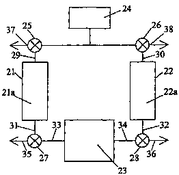
FIG. 2, on the other hand, is a schematic
diagram of an integrated solid polymer fuel cell
stack and pressure swing adsorption system. Here,
fuel cell stack 23 is supplied with a pressurized
reactant stream from supply 24. In part of the
PSA cycle, the pressurized reactant stream is
directed from supply 24 by first valve 25 to
adsorbent chamber 21 (containing first adsorbent
portion 21a) via line 29. A pressurized, reactant
enriched stream is obtained at line 31 and is
directed by valve 27 to fuel cell stack 23 via
line 33. After flowing through the fuel cell
passages, the exhaust reactant stream is directed
through line 34 and is either vented via line 36
(possibly to drive a turbo-compressor or to supply
a burner) or directed via line 32 to purge
adsorbent chamber 22 by valve 28. (As in certain
conventional systems, part of the exhaust stream
may also be recirculated and fed back into the
fuel cell stack again if desired.)
During the initial desorption phase of
SUBSTITUTE SHEET (RULE 26)
CA 02392823 2002-05-29
WO 01/47050 PCT/CA00/01553
- 21 -
adsorbent 22a in adsorbent chamber 22, the
pressure may be reduced by venting to ambient via
lines 30 and 38 using second valve 26 (again
possibly driving a turbo-compressor or the like
during ventir~g). 'T'hereafter, adsoroent chamber 22
may be purged using a portion of the exhaust
reactant stream from line 34. (During purging, it
is desirable not to allow tine pressure in line 34
to drop abnormally, otherwise the performance of
fuel cell stack 23 could be adversely affected.
This can be accomplished by directing an
appropriate portion of the exhaust reactant stream
in line 34 to line 32 via valve 28. Near the end
of this part of the PSA cycle, second valve 26 can
be closed thereby allowing pressure to build in
chamber 22 prior to reversing the flow of the
reactant stream.) The pressure swing employed in
the adsorption/desorption process is thus derived
from the pressure drop that exists between the
reactant stream supply and ambient.
Alternatively, the absolute pressure in chamber 22
can instead be maintained close to the pressure ir_
line 34 during the entire desorption process by
purging chamber 22 with the exhaust reactant
stream from line 34. The exhaust reactant stream
will be somewhat depleted of reactant compared to
the inlet reactant stream at line 33. However,
the exhaust reactant stream may still be
sufficiently enriched relative to the supply gas
from supply 24 for the purpose of effecting
desorption in chamber 22. In this way, a pressure
swing may be achieved, without as much of a swing
SUBSTITUTE SHEET (RULE 26)
CA 02392823 2002-05-29
WO 01/47050 PCT/CA00/01553
- 22 -
in absolute pressure, via the difference in
partial pressures between the original reactant
stream supply and the fuel cell exhaust. (In
certain circumstances, it may be useful to avoid
urge swings in absolute pressure. For instance,
certain adsorbents like microporous silica are
subject to attrition as a result of repeated
exposure to large cyclic swings in absolute
pressure. Thus, the lifetime of such adsorbents
~0 might be extended by reducing the magnitude of the
swing in absolute pressure during
adsorption/desorption.)
At an appropriate time in the PSA cycle, the
flows are changed in FIG. 2. The pressurized
15 reactant stream now is directed from supply 24 to
adsorbent chamber 22 via line 30 through second
valve 26 and a pressurized, reactant enriched
stream is now obtained at line 32. The reactant
enriched stream is directed by valve 28 to fuel
20 cell stack 23 via line 34. Meanwhile, adsorbent
21a in adsorbent chamber 21 is desorbed in a
similar manner to adsorbent 22a in the preceding.
The pressure in chamber 21 may similarly be
reduced by venting to ambient via line 37 using
25 first valve 25, and/or a purge of chamber 21 may
be accomplished by using valve 27 to direct a
portion of the exhaust reactant stream from fuel
cell stack 23 at line 33 through line 31 and
ultimately venting out line 37. Again, pressure
~0 can be allowed to build in chamber 21 near the end
of this part of the PSA cycle by closing valve 25.
SUBSTITUTE SHEET (RULE 26)
CA 02392823 2002-05-29
WO 01/47050 PCT/CA00/01553
- 23 -
The embodiment in FIG. 2 offers several
advantages over that of the prior art illustrated
in FIG. i. For instance, the portion of the
reactant stream that is used for purging is
directed through the fuel cell stack first and
thus may be used initially to ger~erate useful
power. The fuel cell stack exhaust, which has
unused excess reactant therein, may then be used
as purge for desorbing purposes (except during any
1G initial depressurizing phase of desorption and
subsequent repressurizing). Further, the flow
direction of the reactant stream in this
integrated fuel cell stack and pressure swing
adsorption apparatus is periodically reversed.
15 Thus, the advantages of flow reversal or switching
as described in U.S. Patent No. 5,935,726 may be
obtained. Generally, these advantages are
achieved by configuring the apparatus such that a
reactant stream line is defined having first and
20 second valve 25 and 26 at each end which provides
a fluid connection through the reactant stream
passages of the fuel cells in the fuel cell stack
23.
FIG. 3 is a schematic diagram of an
25 alternative embodiment of an integrated solid
polymer fuel cell stack and pressure swing
adsorption system. Fuel cell stack 43 is supplied
with a pressurized reactant stream from supply 44.
In part cf the PSA cycle, the pressurized reactant
30 stream is directed from supply 44 by valve 45 to
adsorbent chamber 41 which is directly attached to
fuel cell stack 43. A pressurized, reactant
SUBSTITUTE SHEET (RULE 26)
CA 02392823 2002-05-29
WO 01/47050 PCT/CA00/01553
- 24 -
enriched stream is obtained and directed from
chamber 41 through fuel cell stack 43. After
flowing through the fuel cell flow passages, the
exhaust reactant stream is directed out through
adsorbent chamber 42, which is also directly
attached to fuel cell stack 43 and then through
line 46. The exhaust reactant stream thus purges
and desorbs the adsorbent in adsorbent chamber 42
immediately after exiting fuel cell stack 43. In
the next part of the PSA cycle, the flow is
reversed. The adsorbents in this embodiment are
not vented to ambient pressure during the
desorption phase and thus do not experience a
large absolute pressure swing. Instead, the
embodiment in FIG. 3 relies on a pressure swing
arising from the difference in partial pressure
between the supplied and the enriched exhaust
stream for purposes of desorption. The magnitude
of this partial pressure difference, and hence the
suitability of this embodiment, will depend in
part on the operating stoichiometry of the fuel
cell stack and the extent of enrichment by the
adsorbents. As shown in FIG. 3, valve 45 is a
complex valve incorporating the functions of
valves 25 and 26 in FIG. 2.
FIG. 4 is a schematic diagram of an
alternative embodiment of an integrated solid
polymer fuel cell stack and pressure swing
adsorption system that comprises two separate fuel
cel,.~ stacks. Here, two fuel cell stacks 51 and 52
each contain an adsorbent portion 51a and 52a
respectively located so as to be accessible by the
SUBSTITUTE SHEET (RULE 26)
CA 02392823 2002-05-29
WO 01/47050 PCT/CA00/01553
_ 25 _
reactant stream to be enriched. In part of the
PSA cycle, pressurized reactant stream is directed
from supply 54 by first valve 53 to fuel cell
stack 51 containing adsorbent portion 51a. Here,
.. enrichmer:t occurs within fuel cell stack 51
itself. The exhaust reactant stream: from fuel
cell stack 51 is directed by valve 56 either to
vent via line 58 (again possibly to drive a turbo-
compressor or to supply a burner) or to be
directed to purge adsorbent 52a in fuel cell stack
52 by valve 57.
During the initial desorption phase of
adsorbent 52a in fuel cell stack 52, the pressure
may be reduced by venting to ambient via line 60
using second valve 55. ''hereafter, adsorbent 52a
may be purged using a portion of the exhaust
reactant stream from fuel cell stack 51. Some
power output may be obtained from fuel cell stack
52 during purging albeit at a lower level since
the reactant stream passing through its reactant
passages will be enriched in non-reactant relative
to the reactant in stack 51. (Again, during
purging, it is desirable not to allow the pressure
at the outlet of fuel cell stack 51 to drop
abnormally, otherwise its performance could be
adversely affected. This can be accomplished by
directing an appropriate portion of the exhaust
reactant stream to fuel cell stack 52 via valves
56 and 57. Near the end of this part of the PSA
cycle, second valve 55 car_ be closed thereby
allowing pressure to build in fuel cell stack 52
prior to reversing the flow of the reactant
SUBSTITUTE SHEET (RULE 26)
CA 02392823 2002-05-29
WO 01/47050 PCT/CA00/01553
- 26 -
stream.) At an appropriate time in the PSA cycle,
the flows are changed in FIG. 4 and a similar
sequence is repeated.
In FIG. 4, the two fuel cell stacks 51 and 52
appear to be physically separated. However, both
stacks may be combined into a single unit by
sharing common endplate and compression
mechanisms. The two stacks need only differ in
construction with respect to the plumbing to their
i0 reactant flow passages.
The adsorbent portions ir~ FIG. 4 are located
within fuel cell stacks and should be accessible
to the reactant stream. FIGS. 5a and b
schematically illustrate two possible suitable
ways of incorporating adsorbent within a solid
polymer fuel cell stack. In the cross-sectional
view of FIG. 5a, an adsorbent portion is
incorporated within fuel cell stack 71 in the form
of an adsorbent sub-stack 70. Fuel cell stack 71
2C comprises a stack of fuel cell units each
comprising a first reactant flow field plate 72, a
membrane electrode assembly (MEA) 73, and a second
reactant flow field plate 74. Each MEA 73
comprises an anode, a solid polymer electrolyte
membrane, and a cathode (not shown). First and
second reactant gases are directed through
passages which contact the adjacent electrode in
flow field plates 72 and 74 respectively (the flow
direction of the first reactant gas being
indicated by inlet arrows 77 and outlet arrows
78). Adsorbent sub-stack 70 comprises a stack of
adsorbent units each comprising a flow field plate
SUBSTITUTE SHEET (RULE 26)
CA 02392823 2002-05-29
WO 01/47050 PCT/CA00/01553
_ 27
75 (which may be similar to those in the fuel cell
stack) and an adjacent layer containing adsorbent
76. The reactant stream to be enriched (the first
reactant stream in FIG. 5a) is ir~itially directed
through the passages in flow Meld plates 75 in
adsorbent stack 70 at inlet arrows 79 whereupon
non-reactant is adsorbed by adsorbent 76. The
enriched first reactant stream exits flow field
plates 75 at outlet arrows 80 and then is directed
to first reactant fuel cell flow field plates 72.
FIG. 5b shows a cross-sectional view of
another embodiment incorporating adsorbent within
the fuel cell stack. Here, the fuel cell stack
comprises a stack of fuel cell units 90 each
comprising a first reactant flow field plate 91,
an MEA 92, and a second reactant flow field plate
93. Adsorbent 94 is contained within gas
distribution channels 95 formed in first reactant
flow field plate 91. The flow direction of the
reactant stream in FIG. 5b is perpendicular to the
plane of the figure.
Solid polymer fuel cell stacks generate water
at the cathode and typically require substantial
levels of water in the membrane. Thus, there is
usually a significant water content throughout the
interior of such operational stacks. However,
adsorbents may lose effectiveness in the presence
of water if water, particularly liquid water, is
preferentially adsorbed. Non-polar type
adsorbents (that is, with hydrophobic surfaces)
may be used to reduce this problem. Examples of
non-polar type adsorbents include surface treated
SUBSTITUTE SHEET (RULE 26)
CA 02392823 2002-05-29
WO 01/47050 PCT/CA00/01553
- 28 -
activated carbons (in which surface oxygen groups
have been removed), microporous silica with
hydrophobic surface groups, and silicalite zeolite
(having low aluminum content, for example silica
to aluminum ratios of approximately '000).
Alternatively, polar-type adsorbents that are
sensitive to water might also be contemplated ir~
the wet environment of the fuel cell stack if
water is kept away from the adsorbent. For this
purpose in FIG. 5b, a hydrophobic layer 96 (for
example , microporous GoretexT'~
polytetrafluoroethylene layer) is shown covering
adsorbent 94 in gas distribution channels 95 and
protecting adsorbent 94 from contacting liquid
water in channels 95. If the adsorbents are
located external to the fuel cell stacks (for
example, as in FIG. 2), it may be desirable to
incorporate water knock-out drums between the fuel
cell stacks and the adsorbent portions to protect
the latter from contacting liquid water.
Adsorbent may also be incorporated within a
fuel cell stack in individual adsorbent layers
each associated with one or more MEAs. For
instance, the fuel cell stack may comprise a stack
of fuel cell units including a layer containing an
adsorbent, two reactant flow field plates, and an
MEA. The reactant stream to be enriched is
directed into the appropriate flow field plate
whereupon non-reactant is adsorbed at the
00 adsorbent. Concurrently, the enriched reactant
stream accesses the relevant electrode in the MEA.
Eventually, the reactant stream exits the flow
SUBSTITUTE SHEET (RULE 26)
CA 02392823 2002-05-29
WO 01/47050 PCT/CA00/01553
- 29 -
field plate. Here, the reactant stream is
continually being enriched as it flows through the
flow field plates and thus the extenr. of
enrichment varies throughout. As a result,
.. adsorbent nearest the inlet of the =uel cell stack
will adsorb more non-reactant than will adsorbent
nearest the exhaust of the fuel cell stack. When
the flow and hence the pressure drop of the
reactant stream through the flow field plates is
reversed, adsorbent nearest what is now the inlet
will adsorb more non-reactant and adsorbent
nearest what is now the exhaust will desorb non-
reactant.
Other ways of incorporating adsorbent within
a fuel cell stack may be contemplated. For
instance, a suitable adsorbent may be located in
the electrodes in the MEAs. Where applicable,
this might be accomplished by distributing
adsorbent in electrode substrates or gas diffusion
layers or by distributing adsorbent in the
electrode catalyst layers. In the latter case,
particulate adsorbent might simply be mixed in
with catalyst particles in the catalyst layers.
Alternatively, the adsorbent may actually serve as
a support for the catalyst (wherein catalyst
particles are first deposited onto larger
adsorbent particles that in turn are used to
fabricate electrodes). To be a suitable support
however, the adsorbent should be electrically
conductive, have a high surface area, and not
result in contamination of the catalyst. Some
SUBSTITUTE SHEET (RULE 26)
CA 02392823 2002-05-29
WO 01/47050 PCT/CA00/01553
- 30 -
carbons used as molecular sieves may be suitable
as adsorbents and catalyst supports.
Aside from the modifications required to
physically incorporate adsorbent within the fuel
., cell stack, other modifications may need to be
considered as a result of changes in flow velocity
and/or water management characteristics. For
instance, with adsorbent in the fuel cell stack,
fluid flow rates will decrease as non-reactant is
1u adsorbed from the reactant stream and will
increase as non-reactant is desorbed and joins the
reactant stream. The latter effect can result in
a flow velocity increase near the fuel cell stack
exhaust and may be advantageous in removing
15 product water. Consideration of these effects
may, for example, warrant a change in flow field
design (for example, flow field channels of
varying width or depth as a function of distance
from stack inlets or outlets), in operational
20 conditions, or the like.
Other embodiments of an integrated fuel cell
and pressure swing adsorption system may
additionally be contemplated. For instance, it
may be desirable to use the exhaust reactant
25 stream from the fuel cells in order to desorb non-
reactant from the adsorbent portions without
additionally reversing the flow of the reactant
stream through the fuel cells. This may be
accomplished by the appropriate incorporation of
~0 additional lines and valveVs) in the embodiment o=
FIG. 1 such that the fuel cell exhaust stream from
line 15 can be directed back to adsorbent chambers
SUBSTITUTE SHEET (RULE 26)
CA 02392823 2002-05-29
WO 01/47050 PCT/CA00/015~3
1 and 2 by lines 11 and 12 instead of simply
venting the fuel cell exhaust from line 15.
Alternatively, even simpler embodiments may be
contemplated if enrichment is desired primarily
during br,_ef operating periods (for example,
during startup when the fuel cells are below
normal operating temperature, or where greater or
peak power output is temporarily desired, such as
when accelerating in an automotive application).
_., For example, a single adsorbent portion may be
integrated in the fuel cell system with a by-pass
line provided such that the reactant stream may
normally be directly supplied to the fuel cell
but, for brief periods when desired, may be
15 directed instead over the adsorbent portion and
then to the fuel cell. In this case, the
adsorbent could be desorbed by venting to ambient
pressure during periods of normal operation.
While the preceding description was directed
20 at solid polymer fuel cell types, pressure swing
adsorption apparatus can desirably be integrated
with other fuel cell types. However, since
adsorbents function better at lower temperatures,
it is the relatively low temperature fuel cell
~5 types such as solid polymer electrolyte fuel cells
that are preferred. Adsorption and desorption may
be assisted by augmenting the pressure swings with
swings in temperature (for example, suitably
heating and cooling the adsorbent portions perhaps
J,. by appropriate reversal of the flow direction of
coolant). In addition, while the preceding
embodiments employed two discrete adsorbent
SUBSTITUTE SHEET (RULE 26)
CA 02392823 2002-05-29
WO 01/47050 PCT/CA00/015~3
portions, more than two adsorbent portions or,
alternatively, one continuously distributed
portion may also be employed. Further, while the
preceding embodiments served to adsorb one non-
reactant, more than one non-reactant in a gas
stream may be adsorbed by more than one type of
adsorbent. Still further, although not preferred,
the adsorbent portions need not comprise the same
adsorbent.
iC~ Integrating a fuel cell system with a
pressure swing adsorption system can result in
system simplification and provide for more
efficient usage of the pressurized reactants.
Certain embodiments may also provide for energy
15 savings over conventional alternatives.
While particular elements, embodiments and
applications of the present invention have been
shown and described, it will be understood, of
course, that the invention is not limited thereto
20 since modifications may be made by those skilled
in the art without departing from the scope of the
present disclosure, particularly in light of the
foregoing teachings.
SUBSTITUTE SHEET (RULE 26)