Note : Les descriptions sont présentées dans la langue officielle dans laquelle elles ont été soumises.
CA 02392896 2002-07-09
ITW CASE x.3196
The present invention relates generally to fasten-
er driving tools, and .more particularly to a new and.improv-
ed telescoping support device operatively connected to the
workpiece engagement probe or work contact element of the
fastener driving tool so as to support and stabilize, for
exa~ciple, the second uppermost. fastener of a collated array
or strip of fasteners, and therefore by extension, the re-
maining~fasteners of the collated array or strip of fasten-
ers disposed within the fastener tool magazine, while the
first fastener of the collated array or strip of fasteners
is b4ing readied to be sheared. and separated from the col-
lated array or strip of fasteners and driven through the
tool:discharge bore or muzzle'and into a substrate by~means
of a suitable driver blade mechanism or the like, and in ad-
ditiQn,'the support device also serves to assist in the
shea~~.ng ~ and separation of the first uppermost fastener.. from .
the ~ernaining fasteners disposed within the collated strip
24 or ax~ay of fasteners, as well as to prevent misalignment of
the first uppermost fastener as the same. is being driven
within and through the drive bore of the tool by the driver
blade mechanism.
CA 02392896 2002-07-09
In connection with the attachment, for example, of
sheathing materials to substrates comprising, for example,
light to medium gauge steel, the fastener installation tools
conventionally being used are most often electrically-power-
ed screw guns. These tools, however, are often cumbersome
and are sometimes deficient in the armount of power they can
generate in connection with the driving of the fasteners i.n-
. to the light to medium,gauge steel substrates. As an alte~rn-
0 ative to the aforenoted electrically-powered screw guns,
pneumatically-powered fastener driving tools have been uti-
lized, however, such pneumatically-powered fastener-driving
tool have not been deemed commercially acceptable, and
therefore has not enjoyed widespread commercial success, in
view°of the need for an air compressor and operatively asso-
crated air hose in order to power the tool. In addition,
suchlpneumatically-powered tools also ex~hlbit some of the
operational drawbacks characteristic of the electrically-
powered screw guns in that they are cumbersome to use and do
not consistently generate the requisite amount.of power re-
quire. to drive the fasteners in order to, for example, se-
curev.exterior sheathing materials to steel frames~or sub-
strates. Portable, self-contained combustion-powered fasten-
er diving tools~are therefore usually preferred in connec-
Lion with the overall utility, operational convenience~and
efficiency, and~the requisite ;amount of power that can be
generated by means of such fastener driving tools: Tn any
case; regardless of~the particular type of fastener driving
tool'Which is employed, all conventional fastener driving
tools.cornprise internal structural assemblies which exhibit
2
CA 02392896 2002-07-09
or present potential problems or difficulties in connection
with the continuous operation of the fastener driving tools
in an operationally consistent and efficient manner whereby
frequent operational.shut-downs o~ the tool., because of ne-
cessary repair or maintenance procedures, are effectively
obviated. .
For example, in connection with conventional fas-
.tener driving tools wherein a plurality of fasteners are
disposed within the.tool magazine by means of a collated ar-
ray or strip of fasteners, it is desirable and important to
maintain proper coaxial alignment of the first uppermost
fastener within the drive bore and muzzle sections of the
. fastener driving tool as the first uppermost fastener is
being driven through the drive bore~and muxzle sections of
the fastener driving tool such that first uppermost driven
fastener does not become dammed within the tool, or in ad--
dition,Isuch that the first uppermost driven fastener is not
ultimately improperly inserted and installed, that is, in a
skewed or tilted manner, within the particular substrate in-
to which the fastener is desirably being installed. In addi-
tion,I it is likewise desirable and important that the second
uppermost fa'sterier within the collated array or strip of
fasteners, and thereby, by extension, all of the remaining
or residual fasteners within t:he collated array o~ strip of
fasteners,'be properly~support;ed and stabilized in order to
prevent or reduce severe shock or vibrational forces from
being impressed upon all of such remaining or residual fas-
fc
tenexs of the collated array or strip of fasteners disposed
withi~i the tool magazine so as to effectively prevent the
30structural integrity of the collation strip or band securing
3
CA 02392896 2002-07-09
,the plurality of fasteners together within the collated ar-
ray or strip of fasteners from being adversely affected
whereby, for example, any shredding or even partial disinte-
gration of the same could result in improper support and
jamming of the fasteners within the tool magazine. Still yet
further, it is desirable and important. to ensure that the
first uppermost fastener is properly sheared and separated
from the remaining or residual fasteners, comprising the
collated array or strip of fasteners disposed within the
tool magazine, at a substantially precise proper location
such that the first uppermost fastener does not become mis-
aligned within the drive bore and muzzle sections of the
fsatener driving tool, or that excess collation strip debris
.. is not generated, either one of which scenarios can cause
jamming of the tool and operational inefficiency.
.. A need therefore exists in the art for a new and
improved telescoping support device operatively connected to
the workpiece engagement probe or work contact element of
the fastener driving tool which can support and stabilize,
for example, the second uppermost fastener of a collated
array or strip of fasteners, and therefore by extension, the
remaining fasteners of the collated array or. strip of fas-
teners disposed within the fastener tool magazine, while the
first fastener of the collated array or strip of fasteners
is being readied to be sheared and separated from the cpal-
lated array or strip of fasteners, and driven in a properly
aligned manner through the_tool discharge bore or muzzle and
into a substrate by means of a suitable driver blade mechan-
ism or the like, which can facilitate the proper shearing
and:~separation of the first uppermost fastener from the re-
4
CA 02392896 2002-07-09
maining or residual fasteners of the collated array or strip
of fasteners disposed within the tool magazine, and which
can facilitate the proper coaxial alignment of the first up-
permost fastener while the same is being driven through the
drive bore and muzzle sections of the fastener driving tool.
Accordingly, it is an object of the present inven-
tion to provide a new and improved telescoping support de-
vice operatively connected to the workpiece engagement probe
or work contact element of the fastener driving tool so as
to support, for example, the second uppermost fastener of a
collated array or strip of fasteners, and therefore by ex-
tension, the remaining fasteners of the collated array or
strip of fasteners disposed within the fastener tool maga-
zine, during a fastener driving operation.
~Another object of the present invention is to pro-
vide a new and improved telescoping support device opera-
tively connected to the workpiece engagement probe or work
contact element of the fastener driving tool so as to sup-
port, for example, the second uppermost fastener of a col-
lated array or strip of fasteners, and therefore by extpen-
sion, the remaining fasteners of the collated array or strip
of fasteners disposed within the fastener tool magazine,
during a fastener driving operation~so as to overcome the
variqus operative disadvantages and drawbacks characteristic
of PRIOR ART fastener driving tools.
5
CA 02392896 2002-07-09
An additional object of the present invention is
to provide a new and improved telescoping support device op-
eratively connected to the workpiece engagement probe or
work contact element of the~fastener driving tool so as to
support, for example, the second uppermost fastener of a
collated array or strip of fasteners, and therefore by ex-
tension, the remaining fasteners of the collated array or
strip of fasteners disposed within the fastener tool maga-
zine, during a fastener driving operation so as to provide
the second uppermost fastener with a requisite amount of
support and stability.
A further object of the present invention is to
provide a new and improved.telescoping support device opera-
tively connected to the workpiece engagement probe or work
contact element of the fastener driving tool so as to sup-
port, for example, the second uppermost fastener of a col-
lated array or strip of fasteners, and therefore by exten-
sion, the remaining fasteners of the collated array or strip
of fasteners disposed within the fastener tool magazine,
during a fastener,driving operation so as to facilitate the
proper shearing and separation of the first uppermost fas-
tener of the collated array or strip of fasteners from the '
remaining fasteners disposed within the tool magazine.
A last object of the present invention is toppro-
wide a new and improved telescoping support device opera-
tively connected to the workpiece engagement probe or work
contact element~of the fastener driving tool so as to sup-
portf for example, the second~uppermost fastener of a col-
lated array or strip of fasteners, and therefore by exten-
6
CA 02392896 2002-07-09
lion, the remaining fasteners of the collated array or strip
of fasteners disposed within the fastener tool magazine,
during a fastener driving operation so as to effectively
prevent misalignment of the first uppermost fastener within
the collated array or strip of fasteners during the driving
of the first uppermost fastener through the discharge bore
or muzzle of the fastener driving tool.
The foregoing and other objectives are achieved in
accordance with the teachings and principles of~the present
invention through the provision of a new and improved tele-
scoping support device operatively connected to the work-
piece engagement probe or work contact element of the fas-
tener driving tool so as to support, for example, the second
uppermost fastener of a collated array or strip of fasten-
ers, and therefore by extension, the remaining fasteners of
the collated array or strip of fasteners disposed within the
fastener tool magazine, during a fastener driving operation
so as to facilitate the proper shearing and separation of
the first uppermost fastener of the collated array or strip
of fasteners from the remaining~fasteners disposed within
the tool magazine. More particularly, the support devise
comprises a tubular pocket or a pair of prongs within which
the forward or nose portion of the second uppermost fastener
of the collated array or strip of fasteners is disposed when
the workpiece engagement probe or work contact element, and
the support device fixedly mounted thereon, is effectively
7
CA 02392896 2002-07-09
moved rearwardly as the fastener driving tool is moved for-
wardly toward the substrate into which the fasteners are to
be driven. The forward or nose portion of the second upper-
most fastener within the collated array or strip of fasten-
s ers is therefore adequately supported and stabilized such
that the first uppermost fastener within the collated array
or strig of fasteners can in fact be sheared, separated, and
driven in a properly aligned manner through the discharge
bore or muzzle of the fastener driving tool while shock
l0 forces normally imparted to the remaining fasteners within
the collated array or strip of fasteners are optimally mini-
mized. In addition, the support device also structurally co-
operates with the driving bore and muzzle structure so as to
~ facilitate and maintain coaxial alignment of the driven fas-
15 tener within the drive bore and muzzle structures of the
fastener driving tool, and still further, the leading or up-
stream edge or end portion of the support device effectively
serves as a shearing edge so as to ensure proper shearing of
the collation strip at a substantially. precise location
20 halfway between'adjacent pairs of interconnected fasteners
disposed upon the. collated array or strip of fasteners.
H
Various other objects, features, and attendant ad-
vantages of the present invention will be more fully appre-
25 ciated from the following detailed description when consid-
ered in connection with the accompanying drawings in which
8
CA 02392896 2002-07-09
like.reference characters-designate like or corresponding
parts throughout the several views, and wherein:
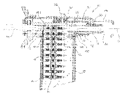
FIGURE 1 is a partial, vertical cross-sectional
view of a fastener driving tool showing the new and improved
support device, constructed in accordance with the teachings
and principles of the present invention, operatively associ-
ated with the workpiece engagement probe or workpiece con-
tact element prior to the rearward movement of the workpiece
engagement probe or workpiece contact element, and the sup-
part device fixedly mounted thereon, 3.n response to forward
movement of the tool toward the substrate into which the
fasteners are to be driven; and
FIGURE 2 is a partial, vertical cross-sectional
view similar to that of FIGURE 1 illustrating, however, the
fastener driving tool, having the new and improved support
device,'constructed in accordance with the teachings and
principles of the present invention, operatively associated
with the workpiece engagement probe or workpiece contact
element, when the workpieee engagement probe or workpiece
contact element, and the support device fixedly mounted
thereon, has in fact been moved rearwardly in response to
the forward movement of, the tool toward the substrate into
which the fasteners are to be driven, such that the support
device is now operatively engaged with the forward or dose
portion of the second uppermost fastener of the collated ar-
ray or strip of fasteners disposed within the tool magazine
so as to support and stabilize such second uppermost fasten-
er while simultaneously facilitating the shearing and sepa-
ration of the first'uppermost fastener from the remaining
9
CA 02392896 2002-07-09
fasteners disposed within the collated array or.strip of
fasteners as well as preventing the misalignment of such
first uppermost fastener as such first uppermost fastener is
driven through the driving tool discharge bore or muzzle.
TISt'.T~TT.t~'~,~~,TpTTQ~ p~ m~R L,REFERRED '~~fBQDr~
Referring now to the drawings, and more particu-
larly to FIC~UREB 1 and 2 thereof, a new and improved fasten-
er driving tool, having a new and improved support device
integrally incorporated therein for supporting the second
uppermost fastener of a collated array or strip of fasten-
ers, and~therefore by extension, the remaining fasteners of
a collated array or strip of fasteners disposed within a
fastener tool magazine, during a fastener driving operation,
is disclosed and is generally indicated by the reference
character 10. The fastener driving too1,10 comprises, in
part, a magazine 12 within wha.ch a collated array or strip
of fasteners 14 is disposed such that uppermost ones of the
fasteners 14 can be serially readied for severance, separa-
tion, and discharge from the tool 10 i.n'accordance with a
fastener firing and driving operation. As is conventionally
known, the collated array or strip of fasteners l4 comprises
a plurality of fasteners 14 which are secured together by
means of'a frangible collation strip 1G or other bond means,
which is affixed to, for example, central portions of the
fastener shanks, such that the plurality of fasteners 14 can
CA 02392896 2002-07-09
in effect be loaded into the tool magazine l2 en masse but,
in addition, the plurality of fasteners 14 can also be sub-
sequently individually and serially separated from each oth-
er as the fastener driving tool is sequentially fired so as~
to drive the individual fasteners 14 into a particular sub-
strate. For the purposes of this disclosure, the particular
substrate may comprise, for example, steel framework struc-
ture, not shown, onto which sheathing materials 18, as shown
in FTGURE 2, are to be fixedly secured.
. As is also conventionally known, the collated ar-
ray or strip 16 of fasteners 14 is operatively associated
with a spring-biasing mechanism, not shown, by means of
which, as viewed in FTGURES 1 and 2, the collated strip l6
of~fasteners 14 will be constantly biased upwardly so as to
serially present and dispose the first. uppermost fastener
14-1 within a fastener tool drive bore 20. The forward,
right, or downstream exit end of the drive bore 20 has a
muzzle member 22 fixedly mounted therein so as to guide the
first uppermost fastener 14-1 toward the substrate, not
shown, as the first uppermost fastener 14-1 is being driven
and discharged from the tool 10, and a suitable driving mem-
ber, .such as, for example, a driver blade or rod 24, is ope-
ratively disposed within the rear, left, or upstream end of
the drive bore 20 so as to engage the head portion of the
first uppermost fastener 14-1 when the tool 10 is fire. The
dxiver blade or rod 24 is adapted, as is also well known, to
be acted upon by means of a piston member, not shown, which
is actuated in accordance with the firing sequence of the
took 10, and it is noted that'the particular fastener driv-
ing tool 10 may either be combustion powered, pneumatically
11
CA 02392896 2002-07-09
powered, powder. actuated, or the like. The fastener driving
tool l0 is further seen to conventionally comprise a work-
piece engagement probe or workpiece contact element 26
which, as is also well known, comprises, in effectr a .safety
mechanism by means of which the tool 10 cannot be fired un-
til the probe or element 26 is initially disposed in contact
with the substrate, into which the fasteners 14 are to be
installed, and subsequently, the tool 10 is moved toward the
substrate so as to effectively cause the workpiece engage-
meat probe or workpiece contact element 26 to be moped rela-
tively rearward~.y or toward the left, as viewed in the draw-
ings, from an extended-position as shown in FIGURE 1 to a
retracted position as shown in FIC~URB 2. Only when these
~ compound or cooperative movements or operations are perform-
ed can the firing mechanism of the fastener driving tool 10
be initiated or actuated whereby the fastener driving tool
30 can then in fact be fired.
In connection with fastener driving tools. similar
to the disclosed~fastener driving tool 10, it can be further
appreciated that when the first uppermost fastener 14-1 is
to lae severed, separated; and driven by means of the driver
rod or blade 24, it is important and desirable to maintain
the coaxial alignment of the first uppermost fastener 14-1
within and with respect to the drive bare 20 and the muzzle
member 22 so as not to cause damming of the fastener 1~4-1
within the tool 10, or improper, that is, tilted or skewed,
insertion or installation within the substrate. zn addition,
it is also important and desirable to adequately support and
stabilize the second uppermost fastener 14-2 within.the tool
magazine 12 such that the first uppermost fastener 14-1 can
12
CA 02392896 2002-07-09
in fact be easily, cleanly; and rapidly severed~and separat-
ed from the remaining fasteners 14 disposed within the col-
lated array or strip 16 of fasteners 14 without the imposi-
tion of severe shock or vibrational forces onto the remain-
ing or residual fasteners 14 disposed within the collated
array or strip 16 of fasteners 14 so as not to adversely af-
feet the structural integrity of the collation strip 16
binding the plurality of fasteners 14 together. In connec-
tion with such severance and separation of the first upper-
most fastener 14-1 from the remaining or residual fasteners
14 disposed within the collated array or strip 16 of fasten-
ers 14, it is likewise-important and desirable to ensure the
fact that the first uppermost fastener 14-1, disposed within
the drive bore 20'of the tool 10, is always severed and sep- '
arated from the remaining or residua3 fasteners 14 disposed
within the collated array or strip 16 of fasteners 14 at
substantially precisely the same location or region of the
collated strip 16, that is, along a shear.plane which is lo-
cated halfway between adjacent ones of the contiguous fas-
teners 14 secured together within the collated array or
strip 16 of fasteners 14, so as to, again,.not cause any
misalignment or jamming of any one of the fasteners 14 with-
in the tool 10,.or so as not to cause the generation of any
excess~collation strip debris within the drive bore 20 which
cou~.d likewise causing jamming of the tool 10.
Tn accordance, therefore, with the unique and nov-
el structure which has been developed in accordance with the
principles and teachings of the present invention, and which
therefore characterizes the import or significance of the
present invention, and with reference again being made to
13
CA 02392896 2002-07-09
FxGrr~s i and 2, it is seen that the fastener driving tool
further comprises a fastener support device 28 which com-
prises a first downstream tubular body section 30 which has
a relatively small diametrical. extent so as to be slidably
5 disposed upon the muzzle member 22, and a second upstream
tubular body section 32 which has a relatively large diame-
trical extent._A first side wall portion of upstream tubular
body section 32 is axially extended so as to define an at-
tachment portion 34 by means of which the fastener support
10 device 28 is fixedly attached to an upstream portion of the
workpiece engagement probe or workpiece contact element 26
through means of a suitable fastener 36, while a second dia-
metrically opposite side wall portion of the fastener sup-
port device 28 is provided with a pair o.f radially inner and
radially outer prongs 38,40 as considered with respect to
the longitudinal axis 42 as defined within the drive bore 20
and muzzle member 22 and along which the first uppermost .
fastener 14-1 will be driven. Tt is to be noted that in lieu
of the provision of the pair of~radially inner and radially
outer prongs 38,40, the support device 28 may be provided
with a single tubular finger which can effectively serve the
same purpose as the two radially inner and radially outer
prongs 38.40.
As can be appreciated from FTGURE 1, when the tool
or apparatus 10 is disposed in its normal, non-workingrmode
whexeby, for example, the workpiece engagement probe or
workpiece,contact element 26 is not engaged or disposed in
contact with a substrate into which fasteners 14 are to be
driven, radially inner prong ~8 is seated upon an upstream
end~portion of the muzzle member 22, while radially outer
14
CA 02392896 2002-07-09
prong 40 is seated upon a downstream end portion of a sup-
port block 42. It is also noted that when the collated ar-
ray or strip 1& of fasteners 14 is operationally mounted
within the magazine 12, the head portion of the second up-
permost fastener 14-2 is seated upon an upstream end portion
of the support block 42, and that a pocket or recess 44,
which is effectively defined between the radially inner and
radially outer prongs 38,40, is coaxially aligned with the
longitudinal axis 46 of the second uppermost fastener 14-2.
It is further appreciated that the downstream end portion of
the support block 42 and the upstream end portion of the
support block 42 axe separated from each other by means of a
space or a slot~48 defined therebetween so as to permit the
~ collated strip 16 of fasteners 14 to pass therethrough.
~As has been noted hereinbefore, in order to opti-
mi.ze the operation of the fastener driving tool 10 without
encountering jamming of the same, or misaligned driving of
the fasteners 14 therefrom and into a particular substrate,
it is imperative that the first uppermost fastener 14-~ be
maintained coaxially aligned within the drive bore 20 and
the muzzle member 22 as the first uppermost fastener 14-1 is
being sheared, separated, arid driven through the drive bore
20 and muzzle member 22 for discharge from the fastener
driving tool 10 and installation into a particular sub-
strate. In addition,. it is likewise imperative that the sec-
and uppermost fastener 14-2 be properly and adequately sup-
ported while the first uppermost fastener 14-1 is being
sheared, separated, and driven through the drive bore 20 and
muzzle member 22 of the fastener driving tool l0 so as to
effectively prevent shock and vibrational forces from being
CA 02392896 2002-07-09
impressed upon the remaining or residual fasteners 14 dis-
posed within the collated array or strip 16 of fasteners 14
so as'not to cause any fracture, disintegration, or other-
wise adverse affects upon the structural integrity of the
collated array or strip l6 of fasteners 14. Lastly, it is
imperative to ensure that the individual fasteners 14 are
sheared and separated from each other at substantially the
same location between each adjacent pair of fasteners 14 so
as not to cause~misalignment of a particular fastener 14 or
to generate excess collation strip debris which could tend
to jam the tool 10. The provision of the support device 28,
constructed in accordance with the principles and teachings
of the present invention, meets and provides the aforenoted
operational requirements.
More particularly, as can be appreciated by means
of a comparison between FIGUREB 1 and 2, when the workpiece
engagement probe or workpiece contact element 26 is moved.,
from the position shown in FIGURE 1, relatively toward the
left, as viewed in the drawings, as the fastener driving
tool 10 is' moved toward the right so as to be moved toward
the substrate into which the fasteners 14 are to be driven,
it is seen that the fastener support device 28 is likewise
moved relatively toward the left, along with the workpiece
engagement probe or contact element 26, to the position, as
shown in FIG'tJRE 2. Accordingly, the prongs 38,40 of the fas-
tener support device 28 will envelop the tip portion of the
second uppermost fastener 14-2 and will simultaneously par-
tia~ly close the opening; space, or slot 48 defined within
the support block 42. Therefore, since the opening, space,
or slot 48~ is now. partially closed, the upstream end portion
16
CA 02392896 2002-07-09
of the fastener support device 28, as defined, for example,
by means of the radially inner prong 38, serves in effect as
an upstream extension of the muzzle member 22 so as to sup-
port the first uppermost fastener 14-1 as the same is begin=
ning to be driven through the drive bore 20 and the muzzle
member 22. In this manner, the first uppermost fastener 14-1
will be properly supported, in a coaxial manner with respect
to longitudinal axis 42, during the driving operation of the
first uppermost fastener 14-1 through the drive bore 20 and
~ the muzzle member 22~by means of the driver blade 24.
It is to be further appreciated that as a result
of the disposition of the tip portion of the second upper-
most fastener 14-2 within the pocket or recess 44 defined
between the radially inner and radially outer prongs 38,40,
the support device 28 provides the necessarily required sup-
port and stability to the second uppermost fastener 14-2,
and by extension, to the entire collated array or strip 16
of fasteners 14, during the driving operation of the first
uppermost fastener 14-1 such that substantial shock and vi-
brational forces, normally impressed upon the collated array
or strip l6 of fasteners 14 as a result of the fastener sev-
Bring and driving operation, are substantially reduced or
minimized whereby damage to, or fractures which would norm-
ally be induced~within, the collated array or strip l6 of .
fasteners 14,, will be effectively prevented. Still further,
it is lastly to be appreciated that the upstream edge por-
tion 50 effectively defines a shearing edge which is sub-
stantially aligned with a shear plane which is located half-
way between adjacent pairs of the fasteners 14. Consequent-
ly; when the driver blade member 24 is actuated so as to '
17
CA 02392896 2002-07-09
drive the first uppermost fastener 14-l toward the right, as
viewed in the drawings, the thermoplastic material from
which the collation strip or band 16 will be somewhat elon-
gated and stretched whereupon encountering the shearing edge
50 of the radially inner prong 38, the driving force impart-
ed to the fastener 14-1, in combination with the shearing
forces impressed upon the collation strip or band 16 by
means of the shearing edge 50, will cause the collation
strip or band 16 to be severed. In addition, it is to be
particularly noted that due to the fixed radial disposition
of the shearing edge 50 of the radially inner prong 38 with
respect to, for example, either one of the axes 42,46, the
severance or shearing of the collation strip 16 at the in-
terface defined between the first and second uppermost fas-
teners l4-1,14-2 will always be the same so as to provide
consistently reliable severance and separation of adjacent
fasteners 14.
It is lastly to be noted that in view of the dis-
position of the support device 28 with respect to the c-ol-
fated array or strip 16 of fasteners 14 disposed within the
tool magazine 12, and mare particularly, in view of the po-
sitipnal relationship defined between the prong members 38,
40 of the support device 28 and the second uppermost fasten-
er 14-2, immediately preceding, during,~and immediately sub-
sequent to the firing and discharge of the first uppermost
fastener 14-1, that is, in view of the fact that the prongs
38,40 effectively envelop the tip portion of the second up- '
permost fastener 14-2 such that the tip portion of the sec-
ond uppermost fastener 14-2 is disposed within the pocket or
recess 44 defined between the prongs 38,40, as shown in FIa-
18
CA 02392896 2002-07-09
ure 2, advancement of the collated array or strip 16 of fas-
teners 14 upwardly within the magazine 12 is effectively
prevented~unless and until the fastener driving tool 10 is
retracted-away from the substrate so as to correspondingly
permit the workpiece engagement.probe or contact element 26
to regain its extended position as shown in F2GURE 1. Such
movement of course correspondingly moves the support device
28 to its position as shown~in FIGURE 1 whereby the interen-
gagement of the support device 28 with the second uppermost
fastener 14-2 is terminated. The collated array or strip 16
of fasteners 16 is now therefore permitted to be advanced
upwardly within the tool magazine 12 whereby the previously
designated second uppermost fastener 14-2 will now be dis
. posed at the position previously occupied by the first up-
permost fastener 14-1 whereupon a new fastener firing cycle
can be commenced.
Thus, it may be seen that in accordance with the
principles and teachings of the present invention, a new and
improved support device has been provided in conjunction
with a fastener driving tool wherein the support device is
fixedly mounted upon the workpiece engagement probe or work-
piece contact element so as to be telescopically movable
therewith between extended and retracted positions, and
wherein further, when the workpiece engagement probe or con-
tact element, and the support device, are moved to their re-
spective retracted positions, the support device will par-
tially close the slot defined within the operatively associ-
ated support block so as to effectively prevent misalignment
of the fastener as the same is being driven through the
drive bore and muzzle member of the tool, the support device
19
CA 02392896 2002-07-09
will envelop the tip portion of the second uppermost fasten-
er so as to support and sta.bilixe the same, as well as the
collated array or strip of fasteners so as to prevent shock
and impact forces attendant a fastener giving operation
from being transmitted to the collated array or strip of
fasteners, and an upstream edge portion of the support de-
vice will serve as a shearing edge so as to consistently
shear and sever the first uppermost fastener from the second
uppermost fastener at a predetermined position or interface
defined halfway between adjacent pairs of fasteners.
Obviously, many variations and modifications of
the present invention are possible in :Light of the above
~ teachings. It is therefore to be understood that within the
scope of the appended claims, the present invention may be
practiced otherwise than as specifically described herein.
25