Sélection de la langue

Search

Sommaire du brevet 2393005 

Énoncé de désistement de responsabilité concernant l'information provenant de tiers

Une partie des informations de ce site Web a été fournie par des sources externes. Le gouvernement du Canada n'assume aucune responsabilité concernant la précision, l'actualité ou la fiabilité des informations fournies par les sources externes. Les utilisateurs qui désirent employer cette information devraient consulter directement la source des informations. Le contenu fourni par les sources externes n'est pas assujetti aux exigences sur les langues officielles, la protection des renseignements personnels et l'accessibilité.

Disponibilité de l'Abrégé et des Revendications

L'apparition de différences dans le texte et l'image des Revendications et de l'Abrégé dépend du moment auquel le document est publié. Les textes des Revendications et de l'Abrégé sont affichés :

  • lorsque la demande peut être examinée par le public;
  • lorsque le brevet est émis (délivrance).
(12) Brevet: (11) CA 2393005
(54) Titre français: ENSEMBLE DE MONTAGE DE ROBINET STABILISE
(54) Titre anglais: STABILIZED TAP MOUNTING ASSEMBLY
Statut: Périmé et au-delà du délai pour l’annulation
Données bibliographiques
(51) Classification internationale des brevets (CIB):
  • F16L 23/00 (2006.01)
  • F16L 41/00 (2006.01)
  • G01L 19/00 (2006.01)
(72) Inventeurs :
  • HUTTON, PETER B. (Etats-Unis d'Amérique)
(73) Titulaires :
  • CENTURY INDUSTRIES COMPANY
(71) Demandeurs :
  • CENTURY INDUSTRIES COMPANY (Canada)
(74) Agent: GOWLING WLG (CANADA) LLP
(74) Co-agent:
(45) Délivré: 2009-01-06
(86) Date de dépôt PCT: 2000-02-03
(87) Mise à la disponibilité du public: 2000-10-26
Requête d'examen: 2004-03-17
Licence disponible: S.O.
Cédé au domaine public: S.O.
(25) Langue des documents déposés: Anglais

Traité de coopération en matière de brevets (PCT): Oui
(86) Numéro de la demande PCT: PCT/US2000/002658
(87) Numéro de publication internationale PCT: US2000002658
(85) Entrée nationale: 2001-10-19

(30) Données de priorité de la demande:
Numéro de la demande Pays / territoire Date
60/129,859 (Etats-Unis d'Amérique) 1999-04-19

Abrégés

Abrégé français

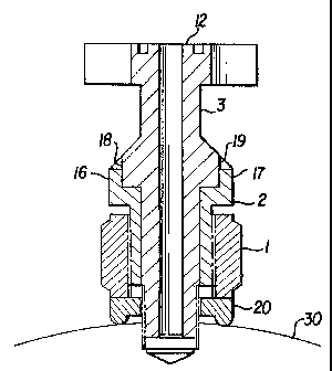
La présente invention concerne un procédé et un appareil permettant de réduire la charge s'exerçant sur les filetages de robinets placés sur une plaque d'orifice ou un raccord d'orifice. Cet appareil comprend un robinet (3) présentant une extrémité filetée NPT (10), une extrémité bridée (12), et une bride intermédiaire (13) qui vient en prise avec un tube de stabilisation (2) placé autour du robinet (3). Lors de son utilisation, un écrou de stabilisation (1), déjà vissé sur le tube de stabilisation (2), est dévissé, ce qui pousse le tube de stabilisation (2) contre la bride intermédiaire (13) et déplace au moins une partie du poids s'exerçant sur les filetages (10) du robinet (3).


Abrégé anglais


A method and apparatus are disclosed to
reduce the load from the threads on taps on an
orifice plate or orifice fitting. The apparatus
includes a tap (3) having an NPT threaded end
(10) and a flanged end (12) and an intermediate
flange (13) which engages with a stabilizing
tube (2) placed around the tap (3). In use, a
stabilizing nut (1), previously threaded on the
stabilizing tube (2), is unthreaded thereby forcing
the stabilizing tube (2) against the intermediate
flange (13) and transferring at least some of the
weight off the threads (10) of the tap (3).

Revendications

Note : Les revendications sont présentées dans la langue officielle dans laquelle elles ont été soumises.


What is claimed is:
1. A tap assembly comprising:
(a) tap comprising a male NPT threaded end and a flanged end, wherein the
tap is further provided with a stabilizing flange integral with the tap;
(b) a separate stabilizing tube having an external thread; and
(c) a stabilizing nut threaded on said stabilizing tube.
2. The tap assembly of claim 1, wherein the stabilizing flange is provided
intermediate the threaded end and flanged end.
3. The tap assembly of claim 1, wherein the stabilizing tube has at least one
projection interfitting with a recess in the stabilizing flange.
4. The tap assembly of claim 3, wherein said at least one projection comprises
two projections interfitting with two mating recesses in the stabilizing
flange.
5. The tap assembly of claim 1, further comprising a manifold attached to the
flanged end of said tap.
6. The tap assembly of claim 1, further comprising a pressure transmitter
attached to the flanged end of said tap.
7. The tap assembly of claim 5, further comprising a pressure transmitter
attached to the manifold.
8. A method of transferring the load on the threads of a pressure tap to a
larger
area than just the threads of the pressure tap, said method comprising:
(a) providing a tap having at one end, male NPT threads and at the other end a
flange and immediate thereto a stabilizing flange;
(b) providing a threaded stabilizing tube;
(c) threading a stabilizing nut on said stabilizing tube;
(d) threading said NPT threads into a source of pressure; and
-6-

(e) unthreading said stabilizing nut on said stabilizing tube to expand the
stabilizing tube and stabilizing nut into a state of compression thereby
transferring at
least some of the load from the NPT threads to the stabilizing flange.
9. The method of claim 8, wherein the source of pressure is an orifice plate
fitting.
10. The method of claim 8, wherein the source of pressure is an orifice
flange.
11. The method of claim 10, further comprising placing a flange shoe between
said orifice flange and said stabilizing nut.
12. The method of claim 8, further comprising attaching a manifold to said end
flange.
13. The method of claim 12, further comprising attaching a pressure
transmitter to
said manifold.
14. The method of claim 8, further comprising attaching a pressure transmitter
to
said end flange.
15. The method of claim 8, further comprising engaging at least one protrusion
on
said stabilizing tube with at least one mating recess on said stabilizing
flange.
16. The method of claim 8, further comprising engaging two protrusions on said
stabilizing tube with two mating recesses on said stabilizing flange.
17. The tap assembly of claim 1, further comprising a flange shoe.
-7-

Description

Note : Les descriptions sont présentées dans la langue officielle dans laquelle elles ont été soumises.


CA 02393005 2001-10-19
WO 00/63603 PCT/US00/02658
STABILIZED TAP MOUNTING ASSEMBLY
BACKGROUND OF THE INVENTION
1. Field of the Invention
This invention relates to the remote sensing of pressure drops across an
orifice plate in
a pipeline and particularly to a stabilized tap mounting assembly to
facilitate, stabilize and reduce
vibration of the transmitter and associated apparatus, such as valved manifold
blocks connecting
the transmitter to taps on an orifice plate or orifice fitting.
2. Description of the Related Art
The gas industry makes extensive use of orifice plates for volume
measurements. Orifice
plates are artificial constrictions in a pipeline. As a result of this
constriction there is a pressure
drop from the upstream side of the orifice plate to the downstream side of the
orifice plate. There
is a relationship between the pressure drop and the amount of gas flowing
through the pipeline.
The pressure drop can be measured which in turn allows a determination of the
flow through the
pipeline.
The pressure drop is measured using electronic transmitters. These
transmitters actually
measure the pressures on both the upstream and downstream sides of the orifice
plate and then
record the difference between the two. Devices of this type are referred as
differential pressure
transmitters. There are numerous manufacturers of this type of device (e.g.
Rosemount,
Honeywell, Foxboro and others).
Orifice plate fittings (such as the type manufactured by Daniel Industries)
and orifice
flanges (manufactured by Daniel and others) are provided with holes (called
taps) both upstream
and downstream of the orifice plate. The taps are generally threaded holes,
typically 1/z" female
NPT (National Pipe Thread - a tapered thread designed to seal pressure tight).

CA 02393005 2001-10-19
WO 00/63603 PCTIUSOO/02658
It is necessary to incorporate valving systems between the orifice taps and
the differential
pressure transmitters. These valving systems need to include the following
functions. Block
valves to isolate the flow through the upstream and downstream taps (generally
referred to as the
high pressure side and the low pressure side), between the orifice flange or
fitting and the
transmitter. An equalizer valve, or valves, to control the connection between
the high pressure
passages and the low pressure passages. A vent valve, or valves, to allow
trapped pressures to
be bled off or to allow the passages to be purged of entrapped gases or
liquids. Sometimes the
vent valve(s) are incorporated into the transmitters.
The natural gas industry has evolved a number of specifications and
requirements to
minimize errors in the measurement of flow and to provide improved accuracy
and response
time. Some of these are:
l. The closer the transmitter is to the orifice plate the better.
2. The orifice size through the valving system from the orifice taps to the
transmitter
must be 3/s" in diameter.
3. The flow passages between the orifice taps to the transmitter should be as
straight
as possible. The ideal is a straight through passage. One 90 degree turn in
the
flow passage is permitted.
Another consideration is mounting the valve system and the transmitters to the
orifice
plate assembly. Conventional mounting, valving, and transmitter assemblies can
weigh 40
pounds and, depending on the complexity of the assembly and the products used,
up to 70
pounds. The pipeline system and the orifice flanges or fittings are subject to
vibration. The
valving and transmitter assemblies also tend to be leaned on by the
instrumentation personnel.
-2-

CA 02393005 2001-10-19
WO 00/63603 PCTIUSOO/02658
Thus, there is a continuing need to provide an alternative connection method
and
apparatus to operatively fluidly couple the high and lower pressure taps about
an orifice plate
with a transmitter.
SUMMARY OF THE INVENTION
The device of the invention has been developed to provide a stabilized mount
to permit
conventional manifold/transmitter assemblies to be attached to orifice
fittings. The novelty of
this device is restricted to the stabilizing mount itself. The manifold shown
in the attached
drawings is commercially available through Century Valve and Machine of
Calgary, Alberta,
Canada and others.
The stabilized tap assembly is designed to mount to both orifice fittings (as
manfactured
by Daniel and others) as well as orifice flanges.
BRIEF DESCRIPTION OF THE DRAWINGS
Fig. 1 is an exploded view of a typical transmitter and block manifold
assembly for use
with the stabilizing taps of the invention;
Fig. 2 is a schematic assembled view of the taps of the invention with a
conventional
manifold.
Fig. 3 is an enlarged view of the taps of the invention of Figs 1 and 2 to
show detail
thereof;
Fig. 4 is a schematic side view of the stabilizing tube of Figs. 1-2.
Fig. 5 is a top view of the stabilizing tube of Fig. 4.
Fig. 6 is a section along A-A of Fig. 4 of the stabilizing tube.
Fig. 7 is a schematic cross section of a flange shoe for use in mounting the
tap of the
invention on an orifice flange; and
-3-

CA 02393005 2007-06-28
WO 00/63603 PCTIUSOO/02658
Fig. 8 is a cross sectional assembled view of the tap and flange shoe on an
orifice flange.
DESCRIPTION OF THE PREFERRED EMBODIMENTS
There are two tap assemblies required for each manifold (4) installation. Each
tap
assembly consists of three pieces. The tap (3), the stabilizing tube (2) and
the stabilizing nut (1).
The tap consists of a male NPT threaded end (10) and a flanged end (12). The
flanged end (12)
is for attachment to a conventional manifold (4). The tap (3) also includes a
stabilizing flange
(13) which is integral with the tap (3) and which is located between the NPT
thread end (10) and
the manifold connection flanged end (12).
The tap (3) is installed as follows. The stabilizing tube (2) and the
stabilizing nut (1) are
threaded together. The tap (3) is inserted through bore (14) in the
stabilizing tube (2) and the
stabilizing nut (1). The tap (3) is threaded into the orifice fitting (5). One
end of the stabilizing
tube (2) has a flat surface (15) with two projections (16)(17). These two
projections (16)(17) fit
into mating recesses (18)(19) on the stabilizing flange (12) located on the
tap (3). The stabilizing
nut (1) is turned on the stabilizing tube (2). The projections (16)(17) on the
stabilizing tube (2)
prevent the stabilizing tube (2) from turning relative to the tap (3). The
lower end of the
stabilizing nut (1) is forced against the orifice fitting (5) while the upper
end of the stabilizing
tube (2) is forced against stabilizing flange (12) on the tap (3). When the
assembly of stabilizing
nut (1) and stabilizi.ng tube (2) is placed in compression, the loads are
transferred from the NPT
threads of tap (3), via the stabilizing flange (12), onto the stabilizing tube
(2) and stabilizing nut
(1), which in turn bears on the orifice fitting (5).
Precision General Inc. (PGI) manufactures a stabilized futbol device which is
covered by
their patent 4,920,626. In PGI's device the tap itself is threaded and the jam
nut threads directly
onto the tap.
-4-

CA 02393005 2001-10-19
WO 00/63603 PCT/USOO/02658
In the invention, the stabilized tap assembly transfers the imposed loads
through a larger
area (the stabilizing flange), rather than just threads on the tap. As a
result, there are lower
stresses imposed on our tap rather than on PGI tap threads.
The same stabilized tap assembly can be used with orifice flanges (30)
(instead of the
orifice taps of Fig. 1) by using a flange shoe (20) (Fig. 7). The flange shoe
(20) is shown on the
cross sectional view of Fig. 8. The device works the same as described above
except that the
stabilizing nut (1) bears on the flange shoe (20). The flange shoe has two
projections (22)(24)
along opposite sides. Those projections are rounded, as shown on the drawings,
and those
projections bear on the flange. The flange shoe can be designed to fit all
flange sizes and ratings.
It will be apparent to those skilled in the art that many modifications can be
made to the
invention without departing from the spirit or scope of the appended claims.
-5-

Dessin représentatif
Une figure unique qui représente un dessin illustrant l'invention.
États administratifs

2024-08-01 : Dans le cadre de la transition vers les Brevets de nouvelle génération (BNG), la base de données sur les brevets canadiens (BDBC) contient désormais un Historique d'événement plus détaillé, qui reproduit le Journal des événements de notre nouvelle solution interne.

Veuillez noter que les événements débutant par « Inactive : » se réfèrent à des événements qui ne sont plus utilisés dans notre nouvelle solution interne.

Pour une meilleure compréhension de l'état de la demande ou brevet qui figure sur cette page, la rubrique Mise en garde , et les descriptions de Brevet , Historique d'événement , Taxes périodiques et Historique des paiements devraient être consultées.

Historique d'événement

Description Date
Le délai pour l'annulation est expiré 2017-02-03
Lettre envoyée 2016-02-03
Accordé par délivrance 2009-01-06
Inactive : Page couverture publiée 2009-01-05
Préoctroi 2008-10-27
Inactive : Taxe finale reçue 2008-10-27
Lettre envoyée 2008-09-17
Inactive : Transfert individuel 2008-06-05
Lettre envoyée 2008-04-28
Un avis d'acceptation est envoyé 2008-04-28
Inactive : CIB attribuée 2008-04-18
Inactive : Approuvée aux fins d'acceptation (AFA) 2008-03-10
Inactive : IPRP reçu 2007-10-29
Modification reçue - modification volontaire 2007-06-28
Inactive : Dem. de l'examinateur par.30(2) Règles 2007-04-10
Inactive : CIB de MCD 2006-03-12
Lettre envoyée 2004-04-28
Inactive : RE du <Date de RE> retirée 2004-04-28
Inactive : Paiement correctif - RE 2004-04-28
Requête d'examen reçue 2004-03-17
Exigences pour une requête d'examen - jugée conforme 2004-03-17
Toutes les exigences pour l'examen - jugée conforme 2004-03-17
Lettre envoyée 2004-03-05
Inactive : Grandeur de l'entité changée 2004-03-04
Requête d'examen reçue 2004-03-01
Inactive : Page couverture publiée 2002-09-09
Inactive : Lettre de courtoisie - Preuve 2002-09-03
Inactive : Supprimer l'abandon 2002-08-29
Inactive : Notice - Entrée phase nat. - Pas de RE 2002-08-28
Inactive : Inventeur supprimé 2002-08-27
Demande reçue - PCT 2002-08-23
Réputée abandonnée - omission de répondre à un avis sur les taxes pour le maintien en état 2002-02-04
Exigences pour l'entrée dans la phase nationale - jugée conforme 2001-10-19
Demande publiée (accessible au public) 2000-10-26

Historique d'abandonnement

Date d'abandonnement Raison Date de rétablissement
2002-02-04

Taxes périodiques

Le dernier paiement a été reçu le 2008-01-21

Avis : Si le paiement en totalité n'a pas été reçu au plus tard à la date indiquée, une taxe supplémentaire peut être imposée, soit une des taxes suivantes :

  • taxe de rétablissement ;
  • taxe pour paiement en souffrance ; ou
  • taxe additionnelle pour le renversement d'une péremption réputée.

Les taxes sur les brevets sont ajustées au 1er janvier de chaque année. Les montants ci-dessus sont les montants actuels s'ils sont reçus au plus tard le 31 décembre de l'année en cours.
Veuillez vous référer à la page web des taxes sur les brevets de l'OPIC pour voir tous les montants actuels des taxes.

Titulaires au dossier

Les titulaires actuels et antérieures au dossier sont affichés en ordre alphabétique.

Titulaires actuels au dossier
CENTURY INDUSTRIES COMPANY
Titulaires antérieures au dossier
PETER B. HUTTON
Les propriétaires antérieurs qui ne figurent pas dans la liste des « Propriétaires au dossier » apparaîtront dans d'autres documents au dossier.
Documents

Pour visionner les fichiers sélectionnés, entrer le code reCAPTCHA :


Pour visualiser une image, cliquer sur un lien dans la colonne description du document (Temporairement non-disponible). Pour télécharger l'image (les images), cliquer l'une ou plusieurs cases à cocher dans la première colonne et ensuite cliquer sur le bouton "Télécharger sélection en format PDF (archive Zip)" ou le bouton "Télécharger sélection (en un fichier PDF fusionné)".

Liste des documents de brevet publiés et non publiés sur la BDBC .

Si vous avez des difficultés à accéder au contenu, veuillez communiquer avec le Centre de services à la clientèle au 1-866-997-1936, ou envoyer un courriel au Centre de service à la clientèle de l'OPIC.

({010=Tous les documents, 020=Au moment du dépôt, 030=Au moment de la mise à la disponibilité du public, 040=À la délivrance, 050=Examen, 060=Correspondance reçue, 070=Divers, 080=Correspondance envoyée, 090=Paiement})


Description du
Document 
Date
(aaaa-mm-jj) 
Nombre de pages   Taille de l'image (Ko) 
Dessin représentatif 2002-08-28 1 9
Revendications 2001-10-18 2 64
Abrégé 2001-10-18 1 51
Dessins 2001-10-18 3 80
Description 2001-10-18 5 185
Description 2007-06-27 5 189
Revendications 2007-06-27 2 66
Dessin représentatif 2008-12-15 1 10
Rappel de taxe de maintien due 2002-08-26 1 109
Avis d'entree dans la phase nationale 2002-08-27 1 192
Accusé de réception de la requête d'examen 2004-03-04 1 176
Avis du commissaire - Demande jugée acceptable 2008-04-27 1 165
Courtoisie - Certificat d'enregistrement (document(s) connexe(s)) 2008-09-16 1 103
Avis concernant la taxe de maintien 2016-03-15 1 169
Avis concernant la taxe de maintien 2016-03-15 1 170
PCT 2001-10-18 6 271
PCT 2001-10-18 1 39
Taxes 2004-01-19 1 34
Correspondance 2004-02-29 2 47
PCT 2001-10-19 4 168
Correspondance 2008-10-26 2 52