Sélection de la langue

Search

Sommaire du brevet 2393146 

Énoncé de désistement de responsabilité concernant l'information provenant de tiers

Une partie des informations de ce site Web a été fournie par des sources externes. Le gouvernement du Canada n'assume aucune responsabilité concernant la précision, l'actualité ou la fiabilité des informations fournies par les sources externes. Les utilisateurs qui désirent employer cette information devraient consulter directement la source des informations. Le contenu fourni par les sources externes n'est pas assujetti aux exigences sur les langues officielles, la protection des renseignements personnels et l'accessibilité.

Disponibilité de l'Abrégé et des Revendications

L'apparition de différences dans le texte et l'image des Revendications et de l'Abrégé dépend du moment auquel le document est publié. Les textes des Revendications et de l'Abrégé sont affichés :

  • lorsque la demande peut être examinée par le public;
  • lorsque le brevet est émis (délivrance).
(12) Demande de brevet: (11) CA 2393146
(54) Titre français: ROBINET PORTANT A SOLENOIDE ET METHODE DE FABRICATION CONNEXE
(54) Titre anglais: A LOAD BEARING SOLENOID OPERATED VALVE AND METHOD OF MAKING SAME
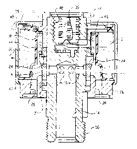
Statut: Réputée abandonnée et au-delà du délai pour le rétablissement - en attente de la réponse à l’avis de communication rejetée
Données bibliographiques
(51) Classification internationale des brevets (CIB):
  • F16K 31/06 (2006.01)
  • F16F 9/348 (2006.01)
  • F16F 9/46 (2006.01)
(72) Inventeurs :
  • OSTERHART, DANIEL J. (Etats-Unis d'Amérique)
  • LAKE, LEWIS W. (Etats-Unis d'Amérique)
(73) Titulaires :
  • EATON CORPORATION
(71) Demandeurs :
  • EATON CORPORATION (Etats-Unis d'Amérique)
(74) Agent: BORDEN LADNER GERVAIS LLP
(74) Co-agent:
(45) Délivré:
(22) Date de dépôt: 2002-07-11
(41) Mise à la disponibilité du public: 2003-01-13
Requête d'examen: 2004-04-26
Licence disponible: S.O.
Cédé au domaine public: S.O.
(25) Langue des documents déposés: Anglais

Traité de coopération en matière de brevets (PCT): Non

(30) Données de priorité de la demande:
Numéro de la demande Pays / territoire Date
09/905,518 (Etats-Unis d'Amérique) 2001-07-13

Abrégés

Abrégé anglais


A load bearing solenoid operated valve having a one piece body with
threads on opposite ends thereof for connection to a system placing the valve
in
tension or compression. An inlet port is formed in one end of the body and a
plurality of cross ports are formed to communicate with the inlet. A sleeve
valve/armature member which is magnetizable is slidably received over the body
and has radial ports which are moved axially for valuing the body cross ports.
An
annular flux collector ring and a pole piece are disposed on the body on
opposite
axial sides of the sleeve valve. A bobbin with coil thereon is received over
the
body and sleeve and a magnetically permeable cover over the coil completes the
flux loop about the coil.

Revendications

Note : Les revendications sont présentées dans la langue officielle dans laquelle elles ont été soumises.


CLAIMS
1. A load bearing solenoid operated valve assembly comprising:
(a) a unitary body member of non-magnetic material having one end
thereof with first surfaces adapted for connection to a first load
applying member and having an end distal the one end having a
fluid pressure inlet port therein and having second surfaces thereon
adapted for connection to a second load applying member opposite
said one load applying member;
(b) at least one side port formed in said body and communicating with
the pressure inlet port;
(c) an annular flux collector disposed on the body;
(d) a sleeve including magnetically permeable material, the sleeve
being disposed over said side port and moveable on the body
between a position preventing and a position permitting flow
through the side port;
(e) an annular pole piece disposed on said body spaced from said
sleeve and distal said flux collector; and,
(f) a coil of electrically conductive material disposed about the sleeve,
wherein upon energization of the coil the sleeve is moved to the
position preventing flow.
2. The assembly defined in claim 1, wherein the sleeve is a unitary member
formed of magnetically permeable material.
3. The assembly defined in claim 1, further comprising a spring biasing the
sleeve to the position permitting flow through the side port.
4. The assembly defined in claim 1, wherein said annular flux collector
defines a port communicating with said at least one side port.
-6-

5. The assembly defined in claim 1, wherein said second surfaces include
surfaces disposed concentrically about the inlet port.
6. The assembly defined in claim 1, wherein said first surfaces comprise
internal threads formed in the body.
7. The assembly defined in claim 1, wherein said sleeve has at least one
cross-port therethrough.
8. The assembly defined in claim 1, wherein said second surfaces include
external threads.
9. The assembly defined in claim 1, wherein said first surfaces define a bore
with terminals disposed therein accessible externally for electrical
connection to the coil.
10. The assembly defined in claim 1, wherein flow through the outlet port is
in
a direction substantially parallel to the pressure inlet port.
11. The assembly defined in claim 1, wherein the inlet port and said first and
second body surfaces are co-axially aligned.
12. A method of making a load bearing solenoid operated valve comprising:
(a) forming first surfaces on one end of a body member adapted for
bearing a load applied in a certain direction and forming second
surfaces adapted for bearing a load in the certain direction on a
second end of the body distal the one end and forming a fluid
pressure inlet port in the second end;
(b) forming in the body at least one side port communicating with the
inlet port;
(c) disposing an annular flux collector on the body;

(d) disposing a magnetizable sleeve over the body and moving the
sleeve between a first position permitting and a second position
preventing flow through the side port;
(e) disposing an annular pole piece on the body and spacing the pole
piece axially from the sleeve to form an air gap with the sleeve;
(f) disposing a coil of electrically conductive material over the sleeve
and energizing the coil and moving the sleeve to the position
preventing flow.
13. The method defined in claim 12, wherein the step of disposing an annular
flux collector includes forming an outlet port therein, and the step of
disposing a sleeve includes forming at least one cross port in the sleeve
and continuously communicating the cross port with the outlet port.
14. The method defined in claim 12, wherein the step of forming first surfaces
on one end of the body member includes forming internal threads in the
body member.
15. The method defined in claim 12, wherein the step of forming second
surfaces on a second end of the body member includes forming external
threads.
16. The method defined in claim 12, wherein the step of forming second
surfaces on a second end of the body member includes forming surfaces
about the pressure inlet port.
17. The method defined in claim 12, further comprising forming an outlet port
in the flux collector.
18. The method defined in claim 12, wherein the step of disposing a coil
includes winding the coil on a bobbin.
-8-

19. The method defined in claim 12, wherein the step of disposing a sleeve
includes forming a plurality of circumferentially spaced radially extending
passages in the sleeve.
20. The method defined in claim 12, wherein the step of disposing a sleeve
includes spring biasing the sleeve toward the position permitting flow.
21. The method defined in claim 12, wherein the step of disposing an annular
pole piece includes disposing a portion of the pole piece within the coil.
22. The method defined in claim 12, wherein the step of disposing a sleeve
includes disposing a portion of the sleeve within the coil.
-9-

Description

Note : Les descriptions sont présentées dans la langue officielle dans laquelle elles ont été soumises.

CA 02393146 2002-07-11
TITLE OF INVENTION
[0001] A Load Bearing Solenoid Operated Valve And Method Of Making
Same.
BACKGROUND OF THE INVENTION
[0002] The present invention relates to solenoid operated hydraulic valves
which are mounted as part of a load bearing assembly such as a damper rod
employed in a motor vehicle suspension system. Solenoid operated hydraulic
valves employed for such applications are subjected to cyclic tensile and
compressive loads on the structural components thereof which are often aligned
in sequence along the central axis of the solenoid armature for achieving
efficiency and economy in manufacturing and assembly.
[0003] As a load bearing member in a suspension system, the valve must
meet certain dimensional requirements in addition to having a load bearing
capability; and, heretofore has resulted in an assembly of components by
weldment and threaded connections which has been found to be prohibitively
expensive for high volume mass production of motor vehicle components
particularly for passenger car and light truck applications. Furthermore,
severe
limitations in allowable dimensional variations have often required post
assembly
machining operations which have added to the manufacturing costs.
[0004] A known valve assembly is shown in FIG. 4 with a first load bearing
end member 1 threadingly engaging a second annular body member 2 with a flux
collector ring member 3 attached to a shoulder or body member 2. Load bearing
member 1 has internal threads 1A formed in the upper end thereof for
attachment to a load applying member. The lower end of body member 2 is
provided with an inlet port 6. The moveable armature/valve member 4 and pole
piece 5 and a ported sleeve member 7 are disposed between members 1 and 2
prior to threaded assembly thereof. The assembly of FIG. 4 is thus relatively
complex by virtue of the plurality of parts and their joining and is
relatively costly
to fabricate and assemble in mass production.
_1_

CA 02393146 2002-07-11
[0005] Thus, it has been desired to provide a solenoid operated hydraulic
valve assembly which is intended to function as a load bearing member in an
assembly and to provide such a device which is easy to assemble and install
and
is relatively low in manufacturing costs.
BRIEF SUMMARY OF THE INVENTION
(0006] The present invention provides a solenoid operated hydraulic valve
intended for use as a structural load bearing member in an assembly and has a
load bearing surface on oppositely disposed ends thereof with an inlet port
aligned with the load bearing surfaces on a one piece valve body having a side
port formed therein which communicates with the inlet port. An annular flux
collector is disposed on the body and a sleeve having magnetically permeable
material is disposed over the side port and movable on the body for opening
and
closing the side port. An annular pole piece is disposed on the body remotely
from the flux collector and a coil of electrically conductive material is
disposed
about the sleeve which is moved upon energization of the coil.
(0007] In the preferred embodiment, the load bearing surfaces and the inlet
port are coaxially aligned and an outlet port communicating with the side port
is
provided and is disposed to discharge in a direction generally parallel to the
inlet
port. The present invention thus provides a unique and novel load bearing
solenoid operated hydraulic valve assembly which has a one piece body with an
inlet port formed therein for insertion as a load bearing member in a fluid
operated system.
BRIEF DESCRIPTION OF THE DRAWINGS
[0008] FIG. 1 is a cross section valve of the present assembly and the
energized state with the side port closed;
[0009] FIG. 2 is a view similar to FIG. 1 with the valve in the de-energized
conditions with the side port open;
(0010] FIG. 3 is a exploded view of the valve of the present invention; and
-2-

CA 02393146 2002-07-11
[0011] FIG. 4 is a cross section of a prior art valve assembly.
DETAILED DESCRIPTION OF THE INVENTION
[0012] Referring to FIGS. 1, 2 and 3, the valve assembly of the present
invention is indicated generally at 10 which has a unitary or one piece body
member 12 preferably having a cylindrical configuration with an inlet port or
bore
14 formed in the lower end thereof which inlet port extends upwardly to
communicate with at least one and preferably a plurality of circumferentially
spaced side ports 16.
[0013] An annular sleeve member 18 is slidably disposed over the body 12
and retained thereon by a flange 20 formed on the lower end of the body. A
pole
piece member, which is magnetizable, is secured on the upper end of the body
denoted by reference numeral 22.
[0014] The sleeve 18 includes at least one, and preferably a plurality, of
circumferentially spaced radially extending ports 24 which are located thereon
so
as to permit opening and closing of the side port 16 by vertical movement of
the
sleeve 18 between the flange 20 and the lower end of the upper pole piece 22.
[0015] A flux collector having a ring like or annular configuration is
received
over the lower end of the body as denoted by reference numeral 26; and, in the
presently preferred practice, flux collector 26 has the outlet port or ports
28
formed therein and extending axially in a generally parallel arrangement with
the
inlet port 14. The outlet ports 28 communicate with the ports 24 in the sleeve
18.
Although the outlet ports are disposed in the flux collector 26 in the
presently
preferred embodiment and extend in parallel arrangement with the inlet port
14, it
will be understood that if other arrangements and orientations of the outlet
ports
are desired, the ports 28 may alternatively be located in members of the valve
other than the flux collector 26.
[0016] The flux collector 26 provides an annular fluid chamber indicated by
reference numeral 32 which surrounds sleeve 18 and communicates the outlet
ports 28 with the cross ports 24 in the sleeve 18.
[0017] A bobbin member 30 is received over the body 12. A coil of electrically
-3-

CA 02393146 2002-07-11
conductive material is disposed about the bobbin as denoted by reference
numeral 36 and is connected to electrical terminals such as terminals 38, 39
disposed in the body and extending outwardly through the upper flange of the
bobbin. It will be understood that the terminals 38, 39 are adapted for
external
electrical connection thereto.
[0018] An outer casing or can of magnetically permeable material is disposed
over the bobbin and coil as denoted by reference numeral 40 and is secured to
the flux collector 26 by any suitable fastening, preferably by material
deformation,
as for example by a rolled-in or crimped flange 42. However, it will be
understood that other expedients may be employed for detaching the can 40 to
the flux collector 26. The sleeve is shown in its upward limit position in
FIG. 1
closing the cross ports 34 and closing a working air gap with the upper pole
piece
22. The sleeve is in the position shown in FIG. 1 when the coil is fully
energized.
[0019] An annular ring or clip 44 is disposed over the upper end of the sleeve
18 and has registered thereagainst the lower end of a spring 46 which has its
upper end registered against an inwardly extending flange 48 formed on the
bobbin. The spring 46 thus serves to bias the clip against the sleeve and
urges
the sleeve in a downward or open position.
[0020] Referring to FIG. 2, the valve assembly 10 is shown in the de-
energized state wherein the spring 46 has moved the sleeve 18 downwardly
causing the lower end thereof to engage the upper surface of flange 20 of the
body. In the position of the sleeve shown in FIG. 2, the exhaust ports 24 and
the
sleeve open the side ports 16 in the body to communicate with the outlet port
28.
[0021] The upper end of the body 12 has an internal thread 48 formed therein
for connection to a first load applying member (not shown). The tower end of
the
body 12 has external threads 50 provided thereon which are adapted for
connection to a second load applying member (not shown) which is intended to
apply a load oppositely directed from the load applied to the upper end of
body
12.
(0022] The present invention thus provides a solenoid operated hydraulic
valve which has a unitary one piece body member for attachment at the opposite
-4-

CA 02393146 2002-07-11
ends thereof to load applying members for use in a system requiring the valve
to
be subjected to tensile or compressive loads. The valve of the present
invention
preferably has the inlet port and the load bearing surfaces on the ends
thereof
disposed in coaxial arrangement. The inlet port end of the valve is preferably
attached to the load applying member with external threads; and, the opposite
end of the valve from the inlet port is preferably provided with internal
threads for
connection to a load applying member. The unique annular sleeve valve
member of the present invention surrounds the body and serves as an armature
and controls flow through side ports communicating with the inlet port. The
valve
of the present invention thus provides a unique one piece body construction
which minimizes manufacturing costs and simplifies the construction of the
valve
and provides robustness in service.
(0023] Although the invention has hereinabove been described with respect to
the illustrated embodiments, it will be understood that the invention is
capable of
modification and variation and is limited only by the following claims.
-S-

Dessin représentatif
Une figure unique qui représente un dessin illustrant l'invention.
États administratifs

2024-08-01 : Dans le cadre de la transition vers les Brevets de nouvelle génération (BNG), la base de données sur les brevets canadiens (BDBC) contient désormais un Historique d'événement plus détaillé, qui reproduit le Journal des événements de notre nouvelle solution interne.

Veuillez noter que les événements débutant par « Inactive : » se réfèrent à des événements qui ne sont plus utilisés dans notre nouvelle solution interne.

Pour une meilleure compréhension de l'état de la demande ou brevet qui figure sur cette page, la rubrique Mise en garde , et les descriptions de Brevet , Historique d'événement , Taxes périodiques et Historique des paiements devraient être consultées.

Historique d'événement

Description Date
Demande non rétablie avant l'échéance 2006-07-11
Le délai pour l'annulation est expiré 2006-07-11
Inactive : CIB de MCD 2006-03-12
Réputée abandonnée - omission de répondre à un avis sur les taxes pour le maintien en état 2005-07-11
Lettre envoyée 2004-05-06
Toutes les exigences pour l'examen - jugée conforme 2004-04-26
Requête d'examen reçue 2004-04-26
Exigences pour une requête d'examen - jugée conforme 2004-04-26
Demande publiée (accessible au public) 2003-01-13
Inactive : Page couverture publiée 2003-01-12
Inactive : CIB en 1re position 2002-09-13
Inactive : Certificat de dépôt - Sans RE (Anglais) 2002-08-26
Exigences de dépôt - jugé conforme 2002-08-26
Lettre envoyée 2002-08-26
Demande reçue - nationale ordinaire 2002-08-26

Historique d'abandonnement

Date d'abandonnement Raison Date de rétablissement
2005-07-11

Taxes périodiques

Le dernier paiement a été reçu le 2004-06-22

Avis : Si le paiement en totalité n'a pas été reçu au plus tard à la date indiquée, une taxe supplémentaire peut être imposée, soit une des taxes suivantes :

  • taxe de rétablissement ;
  • taxe pour paiement en souffrance ; ou
  • taxe additionnelle pour le renversement d'une péremption réputée.

Veuillez vous référer à la page web des taxes sur les brevets de l'OPIC pour voir tous les montants actuels des taxes.

Historique des taxes

Type de taxes Anniversaire Échéance Date payée
Taxe pour le dépôt - générale 2002-07-11
Enregistrement d'un document 2002-07-11
Requête d'examen - générale 2004-04-26
TM (demande, 2e anniv.) - générale 02 2004-07-12 2004-06-22
Titulaires au dossier

Les titulaires actuels et antérieures au dossier sont affichés en ordre alphabétique.

Titulaires actuels au dossier
EATON CORPORATION
Titulaires antérieures au dossier
DANIEL J. OSTERHART
LEWIS W. LAKE
Les propriétaires antérieurs qui ne figurent pas dans la liste des « Propriétaires au dossier » apparaîtront dans d'autres documents au dossier.
Documents

Pour visionner les fichiers sélectionnés, entrer le code reCAPTCHA :


Pour visualiser une image, cliquer sur un lien dans la colonne description du document. Pour télécharger l'image (les images), cliquer l'une ou plusieurs cases à cocher dans la première colonne et ensuite cliquer sur le bouton "Télécharger sélection en format PDF (archive Zip)" ou le bouton "Télécharger sélection (en un fichier PDF fusionné)".

Liste des documents de brevet publiés et non publiés sur la BDBC .

Si vous avez des difficultés à accéder au contenu, veuillez communiquer avec le Centre de services à la clientèle au 1-866-997-1936, ou envoyer un courriel au Centre de service à la clientèle de l'OPIC.


Description du
Document 
Date
(aaaa-mm-jj) 
Nombre de pages   Taille de l'image (Ko) 
Dessin représentatif 2002-10-07 1 18
Page couverture 2002-12-30 1 49
Abrégé 2002-07-11 1 21
Description 2002-07-11 5 247
Revendications 2002-07-11 4 128
Dessins 2002-07-11 3 105
Courtoisie - Certificat d'enregistrement (document(s) connexe(s)) 2002-08-26 1 112
Certificat de dépôt (anglais) 2002-08-26 1 163
Rappel de taxe de maintien due 2004-03-15 1 110
Accusé de réception de la requête d'examen 2004-05-06 1 176
Courtoisie - Lettre d'abandon (taxe de maintien en état) 2005-09-06 1 173