Note : Les descriptions sont présentées dans la langue officielle dans laquelle elles ont été soumises.
CA 02393282 2002-05-31
WO 01/51772 PCT/USO1/00273
-1-
TURBINE BLADE AND METHOD OF REPAIR
BACKGROUND OF THE INVENTION
This invention relates generally to the field
of turbine blades, and more particularly to the
field of the repair of the tip portion of turbine
blades.
Figure 1 illustrates a turbine blade 10 as is
known in the prior art for use in power generating
turbines, such as in the first row of blades of a
gas or combustion turbine. Turbine blade 10
includes a blade root 12, an airfoil portion 14, and
a tip portion 16. The blade root 12 is designed to
be inserted into and retained by a disc on a
rotating shaft (not shown) of the turbine. Airfoil
portion 14 is shaped to extract energy from
combustion gases passing over the airfoil portion
14, thereby imparting rotating mechanical energy to
the turbine shaft. For modern gas turbine engines,
airfoil portion 14 is designed to include one or
more cooling passages formed below the sux-face of
the airfoil for the passage of cooling aiz- necessary
to insure the integrity of the blade material in the
hot combustion gas environment. Such cooling
passages may be formed in a forged blade by a
drilling process or may be formed directly in a cast
material blade. For cast turbine blades, the
cooling ~~assages are formed by supporting a ceramic
core within the volume of the mold as the material
of the blade is cast. In order to support the
ceramic core in its proper position during the
CA 02393282 2002-06-O1
11-01-2002 US010027~
-2-
casting process, it is necessary to extend a portion
of the core to the edge of the casting, thereby
creating one or more openings in the tip portion 16
of the as-cast blade. These openings must then be
sealed during the fabrication of the blade in order
to assure the proper flow of the cooling air within
the turbine blade 10. If the size of the opening is
sufficiently small, it may be sealed by a weld plug
18 formed on the tip 16 of the blade 10. For larger
openings it may be necessary to cover the opening
with a cap such as one~or more plates 20 in order to
seal the opening. United States Patent 4,073,599
issued on February 14, 1978, to Allen et al.
describes such a blade tip closure design_ _
Plates 20 are
mechanically restrained by the structure~of the
blade tip 16 and axe held in position and sealed by
one or more brazed joints 21. It may be appreciated
that_the assembly.and brazing of plates 20 can be a .
difficult and expensive process. Furthermore, in
spite of efforts to maintain the core in its proper
position during the casting process, many cast
blades are rejected due to a minimum. wall violation
caused by unintended movement of the core resulting
in an end of a cooling passage being located
proximate a surface of a tip end of the airfoil of
the blade.
Turbine blade 10 is designed to rotate within a
casing (not shown). It is important for the blade
tip 16 to fit precisely within the casing in order
to minimize the passage of combustion gases around
AMENDED SHEET
CA 02393282 2002-06-O1
11-01-2002 USO'10027~
3
the blade tip 16, since such bypass gases impart no energy to the airfoil
section 14. The
blade tip 16 is provided with a squealer 22 which is a raised lip extending
around the
periphery of the blade tip 16. Squealer 22 gets its name from the sound that
is
produced in the event of a mechanical interference between the blade tip 16
and the
casing. Ideally the squealer 22 is sized to fit within the casing without
rubbing but with
a minimum of space therebetween.
It is known that turbine blades 10 may develop one or mare cracks 24 near the
tip 16 of the blade 10 due to low cycle fatigue stresses imparted on the blade
tip 16
during the operation of the turbine. If a crack 24 extends beyond a critical
dimension,
the turbine blade 10 must be removed from service and/or repaired in order to
prevent
catastrophic failure of the blade and turbine. It can be appreciated that a
crack 24 may
be repaired by removing the material adjacent to the crack 24 to form a crack
repair
volume, and then filling the crack repair volume with weld metal. However, the
presence of braze joint 21 utilised to secure plates 20 in position can
complicate the
repair process, since weld integrity is adversely affected when applied over a
braze
material.
US-A-.4,214,355 describes a tuxbine blade tip repair method which involves
attachment of a two-piece tip replacement cap to an existing turbine blade.
The two
pieces of the replacement cap are made separately from each other, and are
attached in
series to the blade which is being repaired.
US-A-5,822,852 describes a method far repairing turbine blade tips by
w; ..
attaching a directionally-solidified or single crystal superalloy replacement
tip to an
existing blade via brazing or resistance welding.
In light of the limitations of the prior art designs, it is desirable to
provide a
method for repairing a cracked hollow turbine blade which overcomes the
problems
associated with the presence of braze material in the proximity of the cracked
AMENDED SHEET
CA 02393282 2005-05-17
- 4 -
area. It is also desired to provide a method of
manufacturing a hollow turbine blade that
precludes the possibility for a repair in the area
of a braze joint. Furthermore, it is desired to
provide a turbine blade having improved level of
performance to prevent the occurrence of cracks
near the blade tip.
SUMMARY OF THE INVENTION
In accordance with an aspect of the
present invention, there is provided a method of
repairing a turbine blade, the blade having a
plurality of cooling passages formed therein
extending to a tip of the blade, the blade further
having a cap brazed over an end of a cooling
passage at the tip and a squealer portion
extending beyond the cap, the method including the
steps of: removing the squealer portion, cap, and
all braze material from the blade to form a repair
surface on the tip; forming a replacement cap
sized to span the plurality of ends of the cooling
passages; attaching the replacement cap to the
repair surface by welding to seal the cooling
passage ends; forming a replacement squealer
portion by a welding process wherein layers of
weld material are deposited to form a squealer.
According to another aspect of the
present invention, there is provided a method of
manufacturing a turbine blade, the method
comprising the steps of: forming a blade root and
CA 02393282 2005-05-17
- 4a -
airfoil portion from a directionally solidified
columnar grained cast material; forming a cap from
a conventionally cast material; welding the cap
onto an end of the airfoil portion; and,
depositing weld material in a welding process to
form a squealer.
According to another aspect of the
present invention, there is provided a method of
repairing a turbine blade, the blade comprising an
airfoil section having a plurality of cooling
passages formed therein, the blade having been
rejected due to a minimum wall violation caused by
an end of a cooling passage being located
proximate a surface of a tip end of the airfoil,
the method comprising: removing a portion of the
tip end of the airfoil to eliminate the portion
containing the minimum wall violation and to form
a repair surface; attaching a cap to the repair
surface by welding; and, depositing weld material
in a welding process to form a squealer.
According to another aspect of the
present invention, there is provided a turbine
blade comprising: a blade root and airfoil
portion comprising a cast directionally solidified
columnar grained material; a cap attached to an
end of the airfoil portion by a weld, the cap
comprising a conventionally cast material; and, a
squealer portion formed on the airfoil portion by
a welding process wherein layers of weld material
are deposited to form a squealer.
CA 02393282 2005-05-17
- 4b -
BRIEF DESCRIPTION OF THE DRAWINGS
Figure 1 is a perspective view of a
prior art turbine blade having a crack formed in
the tip thereof.
Figure 2 is a partial sectional view of
the turbine blade of Figure 1.
CA 02393282 2002-05-31
WO 01/51772 PCT/USO1/00273
-5-
Figure 3 is a partial sectional view of a
turbine blade illustrating a repair made in
accordance with the present invention.
Figure 4 is a schematic representation of the
steps of a method for repairing a turbine blade in
accordance with the present invention.
DETAILED DESCRIPTION OF THE INVENTION
Figure 2 illustrates a partial sectional view
of the prior art turbine blade 10 of Figure 1 as
seen along section 2-2 of Figure 1. Plate 20 and
squealer 22 are seen in sectional view in Figure 2.
For the embodiment shown, the walls 28 of the
turbine blade 10 are integrally cast with the
squealer portion 22. A ceramic core (not shown) is
in place during the casting process to form cooling
passage 26, as well as to form the internal webs 30.
The notches 32, within which plate 20 is retained,
are formed by machining slots into the internal webs
30. Braze material 34 is utilized to hold plate 20
in position within notches 32. Notches 32 provide a
reactive force to counteract the forces imposed upon
plate 20 during the operation of the turbine into
which the blade 10 is installed. As described
above, a crack 24 illustrated in Figure 1 may extend
to portions of blade 10 containing the brazed
material 34.
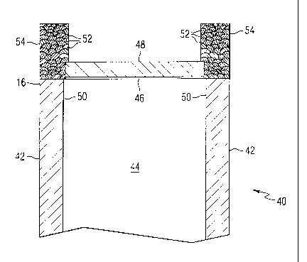
Figure 3 illustrates a turbine blade 40
manufactured or repaired in accordance with the
present invention. The walls 42 of blade 40
correspond to the walls 28 of blade 10 of Figure 2.
CA 02393282 2002-05-31
WO 01/51772 PCT/USO1/00273
-6-
Walls 42 form a portion of the boundary of a cooling
passage 44 that is formed during the casting of the
blade 40. These portions of blade 40 may be formed
during the manufacturing of a new blade or may be
the result of a partial repair process to a blade 10
taken out of service from a turbine. In accordance
with the present invention, blade 10 of Figure 2 may
be repaired to become blade 40 of Figure 3 by a
sequence of steps illustrated schematically in
Figure 4. The first step 41 is to remove the
squealer 22, cap plate 20, and all brazed material
34 from blade 10. The removal of these structures
results in the formation of a repair surface 46 on
the tip 16 of blade 40. The repair surface 46 is
preferably flat and will expose the ends of each of
the cooling passages 44. If the blade 10 had been
rejected for a minimum wall violation, it may be
possible to remove sufficient material to remove the
portion of the blade 10 containing the minimum wall
violation. The webs 30 of Figure 2 are removed in
step 43 to improve thermal characteristics at the
tip and so that the webs 30 will not interfere with
the ability to obtain a successful weld. In
addition, removal of the webs 30 will expand the
size of the opening of cooling passages 44 on repair
surface 46. By improving the access to cooling
passage 44, the inside surfaces 50 of the walls 42
become more accessible for nondestructive
examination (NDE). It may be appreciated that the
prior art blade designs utilize a web to minimize
the core print opening at the tip of the blade,
CA 02393282 2002-05-31
WO 01/51772 PCT/USO1/00273
-
thereby making it easier to close the core print
holes, either by attaching a plate by brazing or by
welding to form a plug if the core print hole is
small enough. A significant amount of effort is
currently being expending in the casting industry to
minimize core print hole size. However, the web
material at the tip of the blade makes it more
difficult to cool the tip of the blade. The current
invention eliminates the problems associated with
having a web for both newly manufactured and
repaired blades.
A replacement cap, illustrated in Figure 3 as
plate 48, is then formed in step 45 to span cooling
passage 44. Advantageously, a single plate 48 may
be used to cover a plurality or all of the cooling
passages 44 formed in blade 40 since the repair
surface 46 is a single flat surface across the
entire cross section of the blade 40. In this
manner, the multiple plate design of the prior art
blade 10 illustrated in Figure 1 is eliminated. The
plate 48 may be sized to span passage 44 leaving
just a small gap between the edges of plate 48 and
the edges of airfoil walls 42 to facilitate the
subsequent welding process discussed below.
The material of plate 48 is chosen to
facilitate the welding of the plate to the airfoil
walls 42. In one embodiment the blade 40 is formed
of a cast. nickel-based super alloy such as IN-738LC,
and both the plate 48 and the weld material 52 used
to secure the plate onto the repair surface 46 are
selected to be the same material as the blade 40.
CA 02393282 2002-05-31
WO 01/51772 PCT/USO1/00273
_g-
For a typical gas turbine row 1 blade, plate 48 may
be in the range of 0.060-0.100 inches in thickness.
Plate 48 may be held in place by mechanical means or
by a tack weld as shown in step 47 of Figure 4
before it is welded to the repair surface 46 in step
49. In one embodiment of the present invention, the
welding process utilized in step 49 is a high
temperature TIG welding process. The applicants
have found that for blades cast either
conventionally, directionally solidified, or as a
single crystal from either IN-738, Mar M247, or CM
247LC material, a pre-heat and an in-process welding
temperature of between 1,650-1,950 degrees
Fahrenheit will provide acceptable results. If a
tack weld is used in step 47, the tack weld and its
heat affected zone are consumed during the welding
of step 49 in order to obtain the more desirable
material properties associate with a high-temperate
TIG welding process.
In the event that the original blade 10 that is
repaired to form blade 40 had developed one or more
cracks 24, as illustrated in Figure 1, the repair
process may include step 51 of removing material
adjacent the crack 24 to form a crack repair volume,
and step 53 of filling the crack repair volume by
welding. Step 55 indicates that nondestructive
examination of the blade 40 may be conducted before
or after the welding of the replacement cap and/or
the repair of any cracks that may be present. For a
newly manufactured blade, it may be appreciated that
steps 41,43,51,53 are not necessary, but are
CA 02393282 2002-05-31
WO 01/51772 PCT/US01/00273
-9-
replaced by the manufacturing of a new blade body
including airfoil section 42 as shown in Figure 3.
In some applications, it may be necessary or
desirable to conduct step 57 of forming a curved
surface on the top surface of plate 48. Step 59
indicates that a replacement squealer portion 54 is
formed by a welding process wherein layers of weld
material are deposited to form the general shape of
squealers 54. Conventional or laser welding may be
utilized for step 59. Step 61 indicates that the
final shape of the blade tip 16 and squealers 54 are
formed by a process such as final machine, grinding,
EDM, or other material shaping process.
In one embodiment of the present invention, the
step 59 of forming the squealer portion may be
performed using a weld filler material that is
different than the weld filler material utilized in
step 49 of welding the replacement cap 48 onto
repair surface 46. The material selected for the
root 12 and airfoil 14 sections of a turbine blade
are primarily selected for their high temperature,
high stress, creep properties. However, the tip 16
portion of a turbine blade 40 experiences a
different set of operating perimeters than the lower
portions of the blade, and failures in the tip
portion 16 are usually the result of low cycle
fatigue, oxidation and corrosion. Therefore, it
may be desirable to select the material for plate 48
and/or replacement squealers 54 to have different
properties than airfoil walls 42.
CA 02393282 2002-05-31
WO 01/51772 PCT/USOl/00273
-10-
The above described embodiments of the present
invention are provided by way of illustration, not
limitation. Accordingly, the full scope of the
applicants' invention is as claimed below.