Note : Les descriptions sont présentées dans la langue officielle dans laquelle elles ont été soumises.
CA 02395528 2002-08-28
TITLE OF THE INVENTION
ACCESS CONTROL METHOD IN COMMUNICATION SYSTEM
BACKGROUND OF THE INVENTION
Field of the Invention
The present invention relates to access control methods, and more particularly
to an access control method in a communication system using a point-to-
multipoint
network structure.
Description o~ the Background Art
The recent trend toward relaxation of regulations in broadcastings and
communications has facilitated fusion of the two and experiments are being
conducted for two-way communications using cable television networks and the
like. In a communication system using a point-to-multipoint network structure
such
as the cable television system, a master station assigns communication
channels
to secondary stations. The secondary stations communicate with the master
station
by using the communication channels assigned. In the polling system, which is
one
of the methods for assigning the communication channels, a master station asks
the secondary stations whether they have transmission messages. When a large
number of secondary stations are accommodated in a communication system,
however, there has been a conventional problem that it takes long before a
transmission message is actually sent out after generated in a certain
secondary
station.
The method explained below is suggested to solve this problem to accommo-
date a large number of secondary stations in a communication system. That is
to
1
CA 02395528 2002-08-28
say, the secondary stations are divided into some groups and the communication
channels are assigned to the groups. Then the master station asks the
secondary
stations, group by group, whether they have transmission messages.
When the method above is applied, however, a large number of secondary
stations in a certain group (hereinafter referred to as "a first group") may
have
transmission messages while only a small number of secondary stations have
transmission messages in another group (hereinafter referred to as "a second
group"). That is to say, a traffic difference occurs between the groups. Then
the
secondary stations belonging to the first group will require a long time
before
actualiy sending ouf a transmission message after it is generated.
Eurth~rmore, if
the traffic on the communication channels assigned to the first group is
congested
in spite of the fact that the communication channels assigned to the second
group
are not being used, the secondary stations belonging to the first group can
not
communicate until a communication channel assigned to the first group becomes
free. This brings about the problem that the secondary stations in the first
group
provide extremely lower response and throughput than those in the second
group.
That is to say, the method above produces the problem that the communication
channels (frequencies, for example) can not be efficiently used in the
communica-
tion system.
SUMMARY OF THE INVENTION
Accordingly, an object of the present invention is to provide an access
control
method in a communication system which enables effective utilization of the
communication channel to provide improved response and throughput of secondary
stations accommodated in the communication system.
2
CA 02395528 2002-08-28
To achieve this object, the present invention includes the following first to
twenty-third aspects, thereby providing the following effects.
A first aspect is directed to a method for controlling access from secondary
stations to a master station in a communication system in which the master
station
and a plurality of secondary stations can bi-directionally communicate,
wherein the master station can use a down-link channel to transfer down-link
signals and each of the secondary stations can use a plurality of up-link
channels
to transfer up-link signals,
wherein the master station detects currently, unused ones) of the up-link
channels (hereinafter referred to as "a free channel°) end selects
onE(s) of the
secondary stations of a number corresponding to the detected free channel(s),
assigns each free channel to each selected secondary station, and
generates a down-link signal for signaling the free channels) assigned to the
selected secondary stations) and sends out the down-link signal onto the down-
link
channel, and
the secondary stations determine whether the up-link channels are assigned
to these stations on the basis of the down-link signal inputted from the down-
link
channel.
In accordance with the first aspect, the master station selects a secondary
station every time a free channel occurs and individually assigns the free
channel
to the selected secondary station. Hence, even if a certain secondary station
makes a communication by using a certain up-link channel in a long time, the
master station can, when another up-link channel becomes free, assign the up-
link
channel to another secondary station. The up-link channels are then always
being
assigned to some of the secondary stations. Then, if a traffic is congested on
an
3
CA 02395528 2002-08-28
up-link channel, it affects not only a particular certain secondary station
but also
affects all secondary stations in a dispersed manner. This improves the
response
and throughput of all the secondary stations accommodated in the communication
system.
According to a second aspect, in the first aspect, each secondary station
sends out the up-link signal onto one of the up-link channels assigned thereto
only
when any of the up-link channels is assigned to this station and it has data
to send
out to the master station.
In accordance with the second aspect, the secondary stations do not send out
up-link signals indicating that they have no data to sand out to the master
station
onto the assigned up-link channels. Hence, the secondary stations do not
require
a structure for performing such transferring processing. This simpfrfies the
structures
of the secondary stations and the master station.
According to a third aspect, in the second aspect, the master station detects
whether an up-link signal is being transferred on each up-link channel in a
certain
period after sending out the down-link signal to detect a free channel.
As stated above, the secondary stations may not send out up-link signals
even when the up-link channels are assigned thereto. If, for example, the
secondary stations send out up-link signals to indicate the absence of up-link
signals to be transferred to the master station onto the assigned up-link
channels,
the master station is required to determine whether the up-link channels are
free
or not on the basis of the up-link signals. Then the master station requires a
long
time to generate a down-link signal. According to the third aspect, however,
when
no up-link signal is sent out onto each up-link channel in a certain period
after a
down-link signal was sent out, the master station can recognize the up-link
channel
4
CA 02395528 2002-08-28
,.
as a free channel and can generate a down-link signal at once. This improves
the
response and throughput of all secondary stations accommodated in the
communication system.
According to a fourth aspect, in the third aspect, the up-link signal includes
an error detecting code,
wherein the master station detects whether an error is occurring in a received
up-link signal on the basis of the error detecting code included in the up-
link signal,
and
when an error is occurring in the received up-link signal, the master station
selects a secondary station otfier than the secondary statior5 to-which the up-
link
channel carrying the up-link signal was assigned, and
assigns the up-link channel carrying the received up-link signal to the
selected
secondary station.
According to a fifth aspect, in the third aspect, the master station detects
whether up-link signals are causing a communication collision on the up-link
channels assigned to the secondary stations,
wherein when detecting the communication collision, the master station selects
a secondary station other than the secondary station to which the up-link
channel
suffering the communication collision is assigned, and
assigns the up-link channel suffering the communication collision to the
selected secondary station.
When a up-link signal is errored or a plurality of up-link signals are causing
a communication collision, the data communication from the secondary station
to
the master station is invalid. If the up-link channel keeps being assigned to
this
secondary station, the invalid data communication occupies the up-link channel
to
CA 02395528 2002-08-28
prevent effective utilization of the up-link channel. Hence, in the fourth or
fifth
aspect, when the master station detects an error in an up-link signal or a
communication collision of up-link signals, it assigns the up-link channel, to
which
that up-link signal was sent out, to a newly selected secondary station to
remove
the invalid data communication from the up-link channel. This improves the
utilization efficiency of the up-link channels.
According to a sixth aspect, in the third aspect, an order for assigning the
up-
link channels to the secondary stations is determined in advance,
wherein the certain order is stored in the master station, and
the master station selects the secondary stations according to the stored
certain order to assign detected free channels.
In accordance with the sixth aspect, the master station can select secondary
stations to assign up-link channels simply by referring to the certain order
without
difficulty. This also allows the certain order for assigning the up-link
channels to
be freely and easily changed.
According to a seventh aspect, in the sixth aspect, the certain order is
determined so that all secondary stations are equally selected by the master
station.
According to the seventh aspect, all secondary stations are equally affected
when the traffic is congested since all secondary stations are equally
selected by
the master station. This improves the response and the throughput of all
secondary
stations accommodated in the communication system.
According to an eighth aspect, in the sixth aspect, the certain order is
determined so that a particular secondary station is selected by the master
station
unequally to other secondary stations.
In accordance with the eighth aspect, when the order is determined so that
6
CA 02395528 2002-08-28
a particular secondary station is unequally selected by the master station,
that is,
so that a particular secondary station is selected more frequently by the
master
station, the particular secondary station provides improved response and
throughput.
According to a ninth aspect, in the third aspect, the master station generates
a dorNn-link signal including a certain command and sends out the down-link
signal
onto the down-link channel, and
the secondary stations execute processing corresponding to the certain
command included in the down-link signal inputted from the down-link channel.
In accordance with the ninth aspect, the down-link signal for signaling free
channels assigned ~o selected secondary stations atso contains a certain
command.
The secondary stations perform processing corresponding to the certain command
contained in the down-link signal inputted from the down-link channel. This
improves the expandability of the access control in the communication system.
A tenth aspect is directed to a method for controlling access from secondary
stations to a master station in a communication system in which the master
station
and a plurality of secondary stations can bi-directionally communicate,
wherein the plurality of secondary stations are divided into a plurality of
groups,
the master station can use a down-link channel to transfer a down-link signal,
and
each secondary station belonging to each group can use a plurality of up-link
channels assigned to each group to transfer up-link signals,
wherein the master station detects currently unused ones) of the up-link
channels (hereinafter referred to as "free channels"),
selects ones) of the secondary stations of a number corresponding to the
detected free channels) from the secondary stations belonging to the group to
7
CA 02395528 2002-08-28
which the free channels) is/are assigned,
assigns each detected free channel to each selected secondary station, and
generates a down-link.signal for signaling the assigned free channels) to the
selected secondary stations) and sends the down-link signal onto the down-link
channel, and
the secondary stations determine whether any of the up-link channels are
assigned to these stations on the basis of the down-link signal inputted from
the
down-link channel.
Various data, such as computer data, audio data, etc., are communicated
between the master station and the secondary stations. However, in general,
while
the audio data is generated, to some degree, in a fixed amount, the computer
data
is generated in various amounts. Furthermore, audio data loses its meaning as
audio data if response and throughput are not ensured. Accordingly, according
to
the tenth aspect, the secondary stations connected to the master station are
divided into a plurality of groups and the up-link channels are assigned group
by
group. When detecting a free channel, the master station selects a secondary
station to assign the free channel from among the secondary stations belonging
to
the group to which the detected free channel is assigned. If, for example,
secondary stations communicating of audio data requiring ensured response and
throughput are grouped, the up-link channels can be periodically assigned to
the
secondary stations belonging to that group. This ensures the response and
throughput at least of the secondary stations in this group.
An eleventh aspect of the present invention is directed to a method for
controlling access from secondary stations to a master station in a
communication
system in which the master station and a plurality of secondary stations can
bi-
8
CA 02395528 2002-08-28
directionally communicate,
wherein the master station can use a down-link channel to transfer a down-
link signal and each secondary station can use a plurality of up-link channels
to
transfer up-fink signals,
wherein the master station detects an up-link channel which is currently not
used (hereinafter referred to as "a free channel"), and
generates a down-link signal for signaling the detected free channel to the
secondary stations and sends out the down-link signal onto the down-link
channel,
and
the secondary stations recognize the up-fink channel which is currently free
from the down-link signal inputted from the down-link channel and send out the
up-
link signal onto the free channel.
In accordance with the eleventh aspect, the master station signals the
information of a detected free channel at once to the secondary stations,
which
prevents the traffic on the up-link channels from being congested.
Furthermore, even
if the traffic is congested on another up-link channel, it affects all
secondary
stations in a dispersed manner, since the secondary stations send out up-link
signals by using free channels detected by the master station. This improves
the
response and throughput of all secondary stations accommodated in the
communication system.
According to a twelfth aspect, in the eleventh aspect, when an error is
occurring in an up-link signal inputted from an up-link channel, the master
station
generates a down-link signal including a data error command indicative of the
occurrence of error and sends it out onto the down-link channel, and
the secondary station which is sending out the up-link signal suspends the
9
CA 02395528 2002-08-28
sending out of the up-link signal on the basis of the data error command.
In accordance with the twelfth aspect, the secondary stations suspend sending
out of data in response to the data error command included in a down-link
signal
inputted from the down-link channel. Since the master station thus causes the
secondary stations to suspend invalid sending out of the up-link signal at the
time
when the data is errored on the up-link channel, the response and throughput
is
improved on the up-link channel.
According to a thirteenth aspect, in the eleventh aspect, the master station
is
detecting the level of a received signal on each up-link channel, and
when the level of ttte received signal has reached or exceeded a certain level
on any of the up-link channels, the master station generates a down-link
signal
including a receive command for signaling that the up-link signal has been
received
to the secondary station sending out the up-link signal onto that up-link
channel,
wherein each secondary station continues to send out the up-link signal on
the basis of the receive command.
In accordance with the thirteenth aspect, the secondary stations can monitor
whether a trouble is occurring in the up-link signals which they sent out onto
the
up-link channels on the basis of the receive command. This removes invalid
signal
sending out and improves the throughput and response in the communication
system.
According to a fourteenth aspect, in the thirteenth aspect, the secondary
stations suspend sending out of up-link signals when they can not recognize
the
receive command in the down-link signal inputted from the down-link channel.
In accordance with the fourteenth aspect, when a secondary station sent out
an up-link signal but finds no receive command in the following down-link
signal,
CA 02395528 2002-08-28
r
the secondary station recognizes occurrence of a trouble in the up-link signal
on
the up-link channel and suspends the transfer of the up-link signal. Since the
secondary station suspends the invalid up-link signal transfer at the time
when a
trouble occurs on the up-link channel, the throughput and the response in the
communication system are improved.
According to a fifteenth aspect, in the eleventh aspect, the master station is
detecting the level of a received signal on each up-link channel, and
when the level of the received signal is lower than a certain level on any of
the up-link channels, the master station recognizes that up-link channel as a
free
channel, and generates a down-link signal inducting a transmission enabling
command for signaling the free channel to each secondary station and sends out
the down-link signal onto the down-link channel,
wherein each secondary station sends out an up-link signal onto the free
channel on the basis of the transmission enabling command.
In accordance with the fifteenth aspect, when the received signal level on an
up-link channel is lower than a certain level, the master station signals that
the up-
link channel is a free channel by using a transmission enabling command. in
other
words, when a signal received on an up-link channel is at the certain level or
higher, the master station recognizes that the up-link channel is used for
communication or is suffering a trouble due to noise and does not signal that
up-
link channel as a free channel to the secondary stations. This prevents the
secondary stations from transferring invalid up-link signals, thus improving
the
throughput and response in the communication system.
According to a sixteenth aspect, in the fifteenth aspect, when the down-link
signal includes a plurality of transmission enabling commands, each secondary
11
CA 02395528 2002-08-28
station, when holding data to send out to the master station, determines that
there
are a plurality of free channels,
selects one free channel from among the plurality of free channels at random,
and
sends out the up-link signal onto the selected up-link channel.
In accordance with the sixteenth aspect, each secondary station can select
one free channel from among a plurality of free channels at random to send out
an
up-link signal, which improves the throughput and response in the
communication
system.
According to a seventeenth aspect, in the eleventh aspect; each secondary
station sends out the up-link signal onto the up-link channel with a
synchronization
pattern set in a certain position in the up-link signal, and
when not detecting the synchronization pattern from the up-link signal
inputted
from the up-link channel, the master station generates a down-link signal
including
a collision detection command for signaling occurrence of a communication
collision
on the up-link channel and sends out the down-link signal onto the down-link
channel,
wherein the secondary station which transferred the up-link signal suspends
the transfer of the up-link signal on the basis of the collision detection
command.
In accordance with the seventeenth aspect, the master station can recognize
a head of an up-link signal transmitted on an up-link channel on the basis of
a
change of the received signal level, and it can also estimate the position in
which
a synchronization pattern is set in the up-link signal. When it detects no
synchronization pattern, the received signal can be regarded as an up-link
signal
whose synchronization pattern was broken by a communication collision on the
up-
link channel. In this case, the master station signals the occurrence of a
12
CA 02395528 2002-08-28
communication collision on the up-link channel by using a down-link signal to
the
secondary station which sent out the up-link signal. This secondary station
suspends the transfer of the up-link signal in response to the communication
collision command included in the down-link signal. The master station thus
causes the secondary station to suspend invalid transmission of up-link signal
at
the time when a communication collision occurs on the up-link channel, thereby
improving the throughput and response in the communication system.
According to eighteenth, nineteenth and twentieth aspects, in the twelfth,
fourteenth and seventeenth aspects, when having suspended transfer of the up-
link
signal, each secondary station retransmits the up-link signal.
In accordance with the eighteenth to twentieth aspects, when having
recognized an invalid up-link signal transmission, the secondary station can
immediately retransmit the data. This further improves the throughput in the
communication system.
A twenty-first aspect is directed to a method for controlling access from
secondary stations to a master station in a communication system in which the
master station and a plurality of secondary stations can bi-directionally
communicate,
wherein the master station can use a down-link channel to transfer a down-
link signal and each secondary station can use a plurality of up-link channels
to
transfer up-link signals,
wherein the master station is detecting the condition of use of each up-link
channel, and
determines on the basis of the condition of use whether to assign an up-link
channel which is currently not used (hereinafter referred to as "a free
channel") to
one of the secondary stations or to signal the free channel to each secondary
station,
13
CA 02395528 2002-08-28
wherein when having determined to assign the free channel to one of the
secondary stations, the master station generates a down-link signal for
assigning
the free channel to the secondary station and sends out the down-link signal
onto
the down-link channel, and
when having determined to signal the free channel to each secondary station,
the master station generates a down-link signal for signaling the free channel
to
each secondary station and sends out the down-link signal onto the down-link
channel.
Generally, it improves the throughput and response in a communication
system to assign a free channel to a particular secondary station when the up-
link
channels are crowded. When the up-link channels are not crowded, however,
allowing the secondary stations to freely send out up-link signals onto free
channels improves the throughput and response. Accordingly, in the twenty-
first
aspect, the master station monitors the conditions of use of the up-link
channels
and determines, on the basis of the conditions of use, whether to assign free
channels to particular secondary stations or to allow the secondary stations
to
freely send out up-link signals onto free channels. Then the master station
can
control accesses from the secondary stations so as to always keep high
throughput
and response.
A twenty-second aspect is directed to a method for controlling access from
secondary stations to a master station in a communication system in which the
master station and a plurality of secondary stations can bi-directionally
communicate,
wherein the master station can use a down-link channel to transfer a down-
link signal and each secondary station can use a plurality of up-link channels
to
transfer up-link signals,
14
CA 02395528 2002-08-28
wherein the master station counts the number of up-link channels which are
currently not used (hereinafter referred to as "the number of free channels")
and
the number of up-link channels currently carrying up-link signals and
suffering a
communication collision (hereinafter referred to as "the number of
communication
collision channels"),
wherein when the number of communication collision channels has reached
or exceeded a first certain number, the master station detects up-link
channels
which are currently not used (hereinafter referred to as "free channels") and
assigns
the free channels to the secondary stations, and
generates a down-link signal for signaling the free channels assigned to the
secondary stations and sends out the down-link signal onto the down-link
channel,
and
when the number of free channels has reached or exceeded a second certain
number, the master station detects free channels and generates a down-link
signal
for signaling the detected free channels to each secondary station and sends
out
the down-link signal onto the down-link channel.
In accordance with the twenty-second aspect, the master station counts the
number of free channels and the number of communication collision channels and
determines whether to assign free channels to particular secondary stations on
the
basis of the number of the communication collisions and determines whether to
allow the secondary stations to freely send out up-link signals onto free
channels
on the basis of the number of free channels. Then the master station can
control
accesses from the secondary stations so as to always keep the throughput and
response high.
According to a twenty-third aspect, in the twenty-second aspect, when the
CA 02395528 2002-08-28
number of communication collision channels has reached or exceeded the first
certain number, the master station detects free channels) and selects ones) of
the
secondary stations of a number corresponding to the detected free channel(s),
and
individually assigns the free channels) to the selected secondary station(s).
In accordance with the twenty-third aspect, the master station selects a
secondary station every time a free channel occurs and individually assigns
the
free channel to the selected secondary station. Even if a certain secondary
station
makes a communication by using a certain up-link channel in a long time, the
master
station can, when another up-link channel becomes free, assign the up-link
channel
to another secondary station. The up-link channels are then always being
assigned
to some of the secondary stations. Then, if a traffic is congested on an up-
link
channel, it affects not only a particular certain secondary station but also
affects all
secondary stations in a dispersed manner. This improves the response and
throughput of all the secondary stations accommodated in the communication
system.
These and other objects, features, aspects and advantages of the present
invention will become more apparent from the following detailed description of
the
present invention when taken in conjunction with the accompanying drawings.
BRIEF DESCRIPTION OF THE DRAWINGS
Fig.1 is a block diagram showing the entire structure of a communication
system to which an access control method of a first embodiment of the present
invention is applied.
Fig.2 is a block diagram showing the details of the structure of the master
station 1 shown in Fig.l.
16
CA 02395528 2002-08-28
Fig.3 is a diagram showing an example of the address table 111 shown in Fg.2.
Fig.4 is a diagram showing the configuration of a down-link frame sent out
from
the master station 1 shown in Fig.2.
Figs.S(a) and (b) are diagrams showing bit configurations of a secondary
station address and various commands set in the address slots shown in Fig.4.
Fig.6 is a block diagram showing the details of the structure of the secondary
station 2 shown in Fig.l.
Figs.7(a) and (b) are diagrams showing an example of configuration of the up-
link frames sent out from the secondary stations shown in Fig.6.
Fig.8 is a flow chart showing the operating procedure of the master station 1
shown in Fig.l.
Fig.9 is a flow chart showing the details of the operating procedure in Step
S3
shown in Fig.B.
Fig.lO is a flow chart showing the operating procedure of the secondary
stations 2 shown in Fig.1.
Fig.l1 is a flow chart showing the details of the operating procedure in Step
S9 shown in Fig.8.
Fig.l2 is a diagram showing transitions of states of the secondary station
addresses set in the address slots in the down-link frames and the
communication
statuses of the up-link channels in the case where an access control method of
a
second embodiment of the present invention is applied.
Fig.l3 is a diagram showing another example of the address table 111 shown
in Fig.2.
Fig.l4 is a diagram showing an example of the address table in a communica-
tion system to which an access control method of a third embodiment of the
17
CA 02395528 2002-08-28
invention is applied.
Fig.l5 is a flow chart showing the operating procedure in which the down-link
frame generating/transferring portionl2 generates a down-link frame in a
communication system to which the access control method of the third
embodiment
of the invention is applied.
DESCRIPTION OF THE PREFERRED EMBODIMENTS
Fig.1 is a block diagram showing the entire structure of a communication
system to which an access control method according to a first embodiment of
the
present invention is applied. In Fig.1, a master station 1 and i 1 secondary
stations
2 (shown are four) are connected to the communication system through the
transmission path 3. This transmission path 3 includes a down-link channel
through which the master station 1 transfers down-link frames and five up-link
channels ch,-chs through which the secondary stations 2 transfer up-link
frames.
Separated frequency bands are individually assigned to the five up-link
channels.
That is to say, this communication system uses the frequency division
multiplex
system. The secondary stations 2 have their respective secondary station
addresses ("a" to "k") previously assigned in such a way that they do not
overlap.
The secondary station to which a secondary station address "a" is assigned is
indicated as a secondary station 2a hereinafter. Other secondary stations 2
are
called secondary stations 2b to 2k as well.
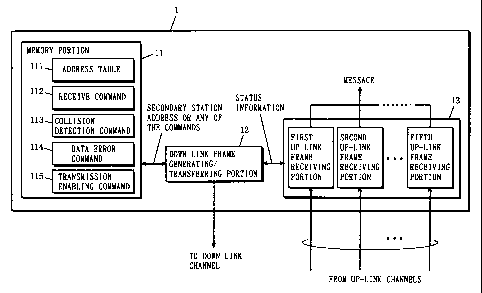
Fig.2 is a block diagram showing the structure of the master station 1 shown
in Fig.1. In Fig.2, the master station 1 includes a memory portion 11, a down-
link
frame generating/transferring portion 12 and an up-link frame receiving
portion 13.
The memory portion 11 contains an address table 111, a receive command
18
CA 02395528 2002-08-28
112, a collision detection command 113, a data error command 114 and a
transmission enabling command 115 in certain address areas.
The address table 111 will be explained first. In this communication system,
the order of assigning free channels (described later) to the secondary
stations is
determined in advance. The address table 111 contains the order associated
with
the secondary station addresses. More specifically, as shown in Fig.3, the
secondary station addresses "a" to "k" ordered from "1" to "11" are stored in
the
address table 111. The above-mentioned four commands, the receive command
112, the collision detection command 113, the data error command 114 and the
transmission enabling command 115 will be explained later.
The down-link frame generating/transferring portion 12 generates down-link
frames and sends out the down-link frames onto the down-link channel. The
procedure of generating the down-link frames will be explained later referring
to
Fig. B, Fig.9 and Fig.ll.
Fig.4 is a diagram showing the configuration of a down-link frame. In Fig.4,
one down-link frame is formed of 16 slots (32 bits/slot), including a header
slot, five
address slots AS,-AS5 and message slots.
The header slot contains a preamble, a synchronization pattern (shown in
Fig.4 as "UW" (Unique Word)) and so on. The synchronization pattern UW has a
certain bit pattern, which is used to establish various kinds of
synchronizations.
One secondary station address or one command is set in each of the address
slots AS, to ASS. In this communication system, the address slots AS, to AS5
correspond to the up-link channels ch, to ch5. For example, setting the
secondary
station address "a" in the address slot AS, indicates that the master station
1
assigns the up-link channel ch, to the secondary station 2a.
19
CA 02395528 2002-08-28 '
Messages from the master station 1 to the secondary stations 2 are stored in
the message slots. This enables communication of data from the master station
1
to the secondary stations 2. The message slots will not be explained herein
because they are not related to the invention.
The preamble, the synchronization pattern UW, the address slots AS,-ASS and
the message slots are set in predetermined bit positions in a down-link frame,
as
shown in Fig.4.
Fig.5 is a diagram showing the bit configurations of a secondary station
address and various commands. Fig.S(a) shows the bit configuration of a
secondary station address. As has been stated above, the secondary station
addresses "a" to "k" are assigned to the secondary stations 2 in an
unoverlapping
manner. However, since a large number of secondary stations 2 are accommo-
dated in an actual communication system, actual secondary station addresses
are
each represented in a 32-bit binary number, as shown in Fig.S(a). Actual
secondary addresses are set "0" in the leading 1 bit and are formed by using
the
remaining 31 bits in an unoverlapping manner.
Fig.S(b) shows the bit configuration of various commands. These commands
are all represented in 32-bit binary numbers, as shown in Fig.S(b), wherein
the
leading 1 bit is set to "1 ", and the last 2 bits are set to "1" and "0". The
remaining
29 bits in the individual commands have different bit patterns each other.
That is
to say, the receive command 112, the collision detection command 113, the data
error command 114 and the transmission enabling command 115 have different bit
configurations from one another.
Now refer to Fig.2 again. The up-link frame receiving portion 13 includes
first
to fifth up-link frame receiving portions 131 to 135 corresponding to the
number of
CA 02395528 2002-08-28
the up-link channels (three of them are shown in the diagram). The first to
fifth up-
link frame receiving portions 131 to 135 apply the following processings to up-
link
frames transmitted on the up-link channels ch,-ch5. The processing in the
first up-link
frame receiving portion 131 is now be explained. The second to fifth up-link
frame
receiving portions 132 to 135 perform the same processing as the first up-link
frame 131.
First, the first up-link frame receiving portion 131 monitors whether an up-
link
frame is transmitted on the up-link channel ch, by using an internal
comparator (not
shown) for a first certain time after a down-link frame was sent out. The
first
certain time is determined considering, for example, the delay time which an
up-link
frame from a secondary station requires to reach the master station.
The comparator compares the level of a reference signal and the level of the
received signal from the up-link channel ch,. This reference signal has a
predetermined certain level. When detecting that the received signal level has
changed from under the certain level to the certain level or higher, the
comparator
outputs a first comparison output. That is to say, the first comparison output
serves
as information indicating that the first up-link frame receiving portion 131
has
detected a head of an up-link frame. When the first certain time has passed
without
a head of an up-link frame detected, the comparator outputs a second
comparison
output if it has detected that the received signal is at the level of the
reference
signal or higher. If, at that time, it has detected that the received signal
level is
lower than the reference signal level, it outputs a third comparison output.
The
second comparison output is information indicating that up-link frames are
being
continuously sent out onto the up-link channel ch,. The third comparison
output
is information indicating that the up-link channel ch, is free. The first up-
link frame
21 .
CA 02395528 2002-08-28
receiving portion 131 thus monitors whether an up-link frame is transferred on
the
up-link channel ch,.
When detecting a head of an up-link frame, the first up-link frame receiving
portion 131 performs detection of the synchronization pattern UW. The
detection
of the synchronization pattern UW is performed in a second certain time after
the
head of the up-link frame was detected. The second certain time is determined
considering the distance on the up-link frame from the head to the bit
position in
which a synchronization pattern UW is estimated to be stored. When detecting a
synchronization pattern UW within the second certain time, the first up-link
frame
receiving portion 131 outputs first receive information (UW detected)
indicating the
detection. When detecting none, it outputs first receive information (UW
undetected) indicting the fact when the second certain time has passed.
When having determined that up-link frames are being continuously sent out,
the first up-link frame receiving portion 131 applies the known technique, FCS
(Frame Check Sequence) to each frame. If it determines that each up-link frame
is being correctly transmitted on the up-link channel ch, without data error,
it outputs
second receive information (valid) indicating the fact. On the other hand, if
it has
determined that a data error is occurring in the up-link frame, the first
up=link frame
receiving portion 131 outputs second receive information (error) indicative of
it.
The first up-link frame receiving portion 131 also performs other processings,
such as taking out a message from an up-link frame, but they are not related
to the
invention and therefore not explained herein.
Fig.6 is a block diagram showing the detailed structure of a secondary station
2 (refer to Fig.1 ). In Fig.6, a secondary station 2 includes a
command/address
detecting portion 21 and an up-link frame generating/transferring portion 22.
When
22
CA 02395528 2002-08-28 w
a secondary station 2 is signaled from the master station 1 that it can send
out up-
link frames through a free channel, it sends out up-link frames by using the
free
channel. Operation of the command/address detecting portion 21 will be
explained
later referring to Fig.lO.
The procedure in which the up-link frame generating/transferring portion 22
generates an up-link frame will be briefly described. A secondary station 2
generates
transmission data, such as video data or audio data, for example. The transmis-
sion data is stored in a buffer memory (not shown) included in the secondary
station 2. The up-link frame generating/transferring portion 22 divides the
transmission data in the buffer memory by every 120 bits. Then it generates an
up-
link frame by adding a 8-bit header to the transmission data corresponding to
the
first 120 bits (refer to Fig.7(a)) and it generates up-link frames by adding a
8-bit
FCS to the following transmission data (refer to Fig.7(b)).
In the communication system explained above, the master station 1 controls
accesses from the secondary stations 2 by using the down-link frames. Fig.B is
a
flow chart showing the operating procedure in which the frame
generating/transferring
portion 12 generates a down-link frame.
In an initial state, no up-link frame is transferred on any of the up-link
channels ch,-ch5. In this state, the first to fifth up-link frame receiving
portions 131-
135 output only the third comparison outputs without performing detection of
the
synchronization pattern UW and the FCS. The first to fifth up-link frame
receiving
portions 131-135 output the comparison outputs and the like to the down-link
frame
generating/transferring portion 12 at certain timings. The certain timings
will be
explained later. A combination of the comparison output, the first receive
information and the second receive information is referred to as status
information
23
CA 02395528 2002-08-28
hereinafter.
The down-link frame generating/transferring portion 12 generates a first down-
link frame under these circumstance. The down-link frame
generating/transferring
portion 12 includes a mode flag a, counters C1, C2 and T, a slot pointer m and
an
address pointer n (not shown). The mode flag a and the counters Ci , C2 and T
are set to "0" and the address pointer n is set to "1" (Fig.B; Step S1).
The down-link frame generating/transferring portion 12 refers to the mode flag
a to determine whether to move to a contention mode (Step S3 explained later)
or
to a polling mode (Step S9 explained later), which takes a value of "0" or "1
". The
counter C1 counts the number of up-link channels on which a communication
collision takes place and the counter C2 counts the number of free channels. A
free channel means an up-link channel on which no up-link frame is being
transferred (no data communication is being made). The counter T measures a
time
period for counting the number of communication collisions and the number.of
free
channels. The address pointer n indicates "nth" one in the order in the
address
table 111, explained above, to specify a secondary station address to be set
in an
address slot AS. Accordingly, the address pointer n counts up one by one from
"1"
to "11 " in this communication system. The slot pointer m will be explained
later
when required.
Next, the down-link frame generating/transferring portion 12 determines
whether the mode flag a is indicating "0" or not (Step S2). If it is
indicating "0", the
down-link frame generating/transferring portion 12 determines that it is
better to
generate a down-link frame in the contention mode and moves to Step S3. On the
other hand, if the mode flag a is not indicating "0" (indicating "1 "), the
down-link
frame generating/transferring portion 12 determines that it is better to
generate a
24
CA 02395528 2002-08-28
down-link frame in the polling mode and moves to Step S9 explained later. At
present, as is clear from the description above, the down-link frame
generating/transferring portion 12 moves to Step S3.
The difference between the contention mode and the polling mode will now
be briefly explained. In the contention mode, a plurality of secondary
stations 2
can send out up-link frames onto one free channel. Therefore it is more prone
to
communication collision than the polling mode. However, the contention mode
allowing the secondary stations 2 to freely send out up-link frames onto free
channels
generally provides higher response than the polling mode.
On the other hand, in the polling mode, the master station 1 assigns one free
channel to one secondary station 2 irrespective of whether it has transmission
data.
Accordingly, it provides lower response than the contention mode. However, the
polling mode in which, as a rule, a plurality of secondary stations 2 do not
send out
up-link frames onto a single up-link channel is less prone to communication
collisions than the contention mode.
However, it is thought that generating down-link frames in the contention mode
when a relatively larger number of channels are free will cause fewer
communica-
tion collisions and provide higher response. Accordingly, in the initial state
in which
all up-link channels are free, it is preferred that the mode flag a is set to
"0" so that
the down-link frame is generated in the contention mode. On the other hand,
when
a relatively smaller number of channels are free, the polling mode less prone
to
communication collisions will provide higher response than the contention
mode.
Fig.9 is a flow chart showing details of the processing procedure in Step S3
(the contention mode) shown in Fig.B. First, the down-link frame generat-
ing/transferring portion 12 sets the slot pointer m to "1" (Fig.9; Step S901).
The
CA 02395528 2002-08-28
slot pointer m specifies an address slot AS in which a secondary station
address
or the above-explained commands are to be set. Since there are five address
slots
in this communication system, the slot pointer m counts up one by one from "1"
to
..5..,
The timing is controlled between the down-link frame generating/transferring
portion 12 and the up-link frame receiving portion 13 so that the status
information
is fed to the down-link frame generating/transferring portion 12 from an rrrth
up-link
frame receiving portion 13m (this "m" corresponds to the indicated value of
the slot
pointer m). Since the slot pointer m is currently indicating "1 ", the status
information is inputted from the first up-link frame receiving portion 131.
Next, the down-link frame generating/transferring portion 12 determines
whether the level of a received signal from an up-link channel specified by
the slot
pointer m (hereinafter referred to as "an up-link channel chm') has varied
from under
the certain level to the certain level or higher (Step S902). If the status
inforfnation
includes the first comparison output, the down-link frame
generating/transferring
portion 12 determines that the level of the received signal has changed and
moves
to Step S908 explained later. If the status information does not include the
first
comparison output, it determines that the level has not changed and moves to
Step
S903. At present, since the down-link frame generating/transferring portion 12
is
receiving the third comparison output from the first up-link frame receiving
portion
131 as stated above, it moves to Step S903.
Next, the down-link frame generating/transferring portion 12 determines
whether the level of the received signal from the up-link channel chm is lower
than
the fixed level (Step S903). When the status information includes the second
comparison output, the down-link frame generating/transferring portion 12
26
CA 02395528 2002-08-28 '
determines that the level of the received signal is at the certain level or
higher and
moves to Step S912 explained later. Wherr the status information includes the
third
comparison output, it determines that the level is lower than the certain
level and
moves to Step S904. At present, the down-link frame generating/transferring
portion 12, receiving the third comparison output, moves to Step S904.
Next, the down-link frame generating/transferring portion 12 accesses the
memory portion 11 to extract the transmission enabling command 115 and then
sets the transmission enabling command 115 into an address slot AS specified
by
the slot pointer m (hereinafter referred to as "an address slot ASm," Step
S904).
The master station 1 thus signals to each secondary station 2 that the up-link
channel chm is free. At present, the slot pointer m indicates "1 " and the
transmis-
sion enabling command 115 is set into the address slot AS,.
Next, the down-link frame generating/transferring portion 12 determines
whether some commands have been set in all address slots AS (Step S905).
When having determined that commands have been set in all address slots AS,
the
down-link frame generating/transferring portion 12 moves to Step S907
described
later. On the other hand, when having determined that commands have not been
set into all address slots AS, the down-link frame generating/transferring
portion 12
moves to Step S906. Since there are five address slots in this communication
system, the determination in Step S905 is made depending on whether the slot
pointer m indicates "5". At present, the slot pointer m is indicating "1" and
therefore the down-link frame generatingftransferring portion 12 moves to Step
S906.
Next, the down-link frame generating/transferring portion 12 updates the slot
pointer m to "m+1" (Step S906) and returns to Step S902 to determine a command
to be set into the next address slot AS. At present, the slot pointer m is
updated
27
CA 02395528 2002-08-28
l
from "1 " to "2."
The timing is controlled so that the status information is, at this time,
being
inputted to the down-link frame generating/transferring portion 12 from an mth
up-
link frame receiving portion 13m indicated by the value of the slot pointer m
after
updated. At present, the status information outputted from the second up-link
frame
receiving portion 132 is inputted.
In the initial state, all up-link channels are free. Accordingly, the down-
link
frame generating/transferring portion 12 repeats the processing procedure
shown
in the order of Steps S902-S906 three times and then executes the processing
procedure shown in the order of Steps S902-S905. As the result, the
transmission
enabling commands 115 are set into the address slots AS2-ASS as well. When
having executed Step S905 with the slot pointer m indicating "5", the down-
link frame
generating/transferring portion 12 moves to Step 5907.
Next, the down-link frame generating/transferring portion 12 sets the preamble
and the synchronization pattern UW into the header slot and messages into the
message slots, if needed, to assemble a down-link frame (refer to Fig.4) and
sends
out this down-link frame onto the down-link channel (Step S907) to end Step S3
in
Fig.B. Operations of the secondary stations 2 receiving this down-link frame
will
be explained later.
Refer to Fig.B again. Next, having finished Step S3, the down-link frame
generating/transferring portion 12 determines whether the counter C1 indicates
a
value equal to or higher than a first certain value (Step S4). The first
certain value
is a value for determining whether the mode flag a should be updated from "0"
to
"1 ". Considering the characteristics of the contention mode and the polling
mode,
this value is set to an appropriate value corresponding to the specifications
of the
28
CA 02395528 2002-08-28
communication system. The first certain value is assumed to be "3"
hereinafter.
When the counter C1 indicates a value not less than the first certain value in
Step S4, the down-link frame generating/transferring portion 12 determines
that it
is suitable to generate a down-link frame in the polling mode and moves to
Step
S5 described later. On the other hand, if the counter C1 is indicating a value
smaller than the first certain value, the down-link frame
generating/transferring
portion 12 determines that it should generate a down-link frame in the
contention
mode and moves to step S6. At present, the indication value "0" of the counter
C1
is smaller than the first certain value "3" and therefore the down-link frame
generating/transferring portion 12 moves to Step S6.
Next, the down-link frame generating/transferring portion 12 updates the
indicated value of the counter T to "T+1 " (Step S6) and determines whether
the
indicated value of the counter T has reached a third certain value (Step S7).
When
determining that the indication value of the counter T has reached the third
certain
value, the down-link frame generating/transferring portion 12 moves to Step S8
explained later. When determining that the indication value of the counter T
has
not reached the third certain value, the down-link frame
generating/transferring portion
12 returns to Step S2. The third certain value is a value for defining an end
of the
time period in which the down-link frame generating/transferring portion 12
measures the number of communication collisions and the number of free
channels.
That is to say, in this communication system, the number of communication
collisions or the number of free channels per period while the counter T
counts from
"0" to "the third certain value" are measured. The third certain value is
assumed
to be "3" hereinafter. At present, the down-link frame generating/transferring
portion 12 updates the counter T from "0" to "1" (Step S6) and then returns to
Step
29
CA 02395528 2002-08-28
S2 since the indication value of the counter T has not reached the third
certain
value "3" (Step S7).
Part of the operations of the secondary stations 2 in this communication
system will now be described referring to the flow chart showing the operating
procedures of the secondary stations 2 in Fig.lO. The command/address
detecting
portion 21 of each secondary station 2 includes a status flag S indicating
"0", or
"1 ", or "2". The status flag S is set to "0" when this system is started
(Step S101 ).
When the status flag S is indicating "0" in a certain secondary station 2, it
means
that the secondary station 2 has no transmission data to the master station 1.
If
the status flag S is indicating "1". in a secondary station 2, it means that
the
secondary station 2 has transmission data to the master station 1 and that the
data
must be transferred from the head. Furthermore, if the status flag S indicates
"2"
in a secondary station 2, it means that the secondary station 2 is being
transmitting
transmission data to the master station 1.
Next, the command/address detecting portion 21 determines whether the
status flag S is indicating "1" (Step S102). If it is indicating "1 ", it
moves to Step
S106 explained later and 'rf it is indicating a value other than "1," it moves
to Step
S 103.
Next, each command/address detecting portion 21 determines whether the
status flag S is indicating "2" (Step S103). If it is indicating "2", it moves
to Step
S111 explained later and if it is indicating a value other than "2" (that is,
indicating
"0"), it moves to Step S104. At present, the status flags S are indicating "0"
in all
of the secondary stations 2 and therefore all command/address detecting
portions
21 execute Steps S102 and S103 and move to Step S104.
Next, each command/address detecting portion 21 determines whether each
CA 02395528 2002-08-28
secondary station 2 has data to be transmitted to the master station 1 (Step
S104).
As stated above, the secondary stations 2 each generate transmission data and
store the data into a buffer memory. The determination in Step S104 is made by
detecting whether transmission data is stored in the buffer memory. When the
buffer memory contains no transmission data, each command/address detecting
portion 21 returns to Step S102. That is to say, the secondary station 2 waits
until
transmission data is generated with the status flag S set at "0." When
transmission
data is stored in the buffer memory, the command/address detecting portion 21
moves to Step S105 to set the status flag S to "1" and returns to Step S102.
Thus,
when transmission data is generated, each secondary station 2 waits for a down-
link frame to be transmitted with the status flag S set at "1 ".
The down-link frame of this time is received at the command/address detecting
portions 21 of all secondary stations 2. At present, the status flag S in each
secondary station 2 is indicating "0" or "1 ". The operation of a secondary
station
2 whose status flag S is indicating "1" will now be described.
If the status flag S indicates "1 " when the down-link frame is transferred
from
the down-link channel (Step S102), the command/address detecting portion 21
moves
to Step S106.
Next, the command/address detecting portion 21 determines whether the
secondary station address of this station 2 is set in any of the address slots
AS (Step
S106). As is clear from the description above, no secondary station addresses
are
set in a down-link frame generated in the contention mode (refer to Fig.B;
Step S3).
The command/address detecting portion 21 hence moves to Step S107. Step S106
will be explained in detail later.
Next, the command/address detecting portion 21 detects whether the
31
CA 02395528 2002-08-28
transmission enabling commands are set in the address slots AS in the down-
link
frame received this time (Step S107). The determination in Step S107 is
typically
made as follows. The command/address detecting portion 21 holds, in advance,
the bit pattern of the transmission enabling command in a register included
therein
(not shown). The command/address detecting portion 21 compares the bit pattern
and that set in the address slot AS1 in the down-link frame to determine
whether
they coincide. If they coincide, it determines that the transmission enabling
command
is set in the address slot AS,. Then the same processing is applied to the
address
slots AS2 ASS. When the transmission enabling command is set in an address
slot
ASm, the comrnand/address detecting portion 21 recognizes that the up-link
channel
chm corresponding to the slot ASm is free. If the transmission enabling
command
is set in any of the address slots AS, the command/address detecting portion
21
moves to Step S108. Since transmission enabling commands are set in the
address
slots AS,-AS5 in this down-link frame, the command/address detecting portion
21
moves to Step S108.
When the transmission enabling command is stored in none of the address
slots AS, the command/address detecting portion 21 determines that no channel
is free and returns to Step S102, and waits for a new down-link frame to be
transmitted.
Next, the command/address detecting portion 21 selects, at random, one
address slot ASm from among the address slots AS containing transmission
enabling commands (Step S108) and signals to the up-link frame generat-
ing/transferring portion 22 to send out an up-link frame by using the up-link
channel
chm corresponding to that slot ASm (Step S109). Then the command/address
detecting portion 21 latches, into a register (not shown), the address slot
ASm
32
CA 02395528 2002-08-28
)
selected in Step S1 OS as a used channel information. This used channel
information is used in Step S111 described later.
The up-link frame generating/transferring portion 22 generated an up-link
frame as shown in Fig.7(a) at the time when the status flag S has been set to
"1 ",
and it sends out the frame onto the up-link channel chm specified by the
command/address detecting portion 21.
Having finished the Step S109, the command/address detecting portion 21
changes the status flag S from "1" to "2" (Step S110) to indicate that the up-
link
frame generating/transferring portion 22 is transmitting up-link frames to the
master
station 1.
For more spec'rfic description, it is assumed that, in response to the first
down-
link frame, the secondary station 2a sends out an up-link frame onto the up-
fink
channel ch,, the secondary station 2b onto the up-link channel ch2, the
secondary
station 2c and the secondary station 2d onto the up-link channel chi, arid the
secondary station 2f and the secondary station 2j onto the up-link channel
ch4. No
up-link frame is sent out onto the up-link channel chs.
Under these circumstance, no communication collision occurs on the up-link
channel ch, and the synchronization pattern UW in the up-link frame sent out
from
the secondary station 2a is not broken. Accordingly, the first up-link frame
receiving
portion 131 can detect the head of the up-link frame and the synchronization
pattern UW and outputs the first comparison output and the first receive
information
(UW detected) as the status information. Since the up-link channel ch2 is in
the
same condition as the up-link channel ch,, the second up-link frame receiving
portion 132 outputs the same status information as the first up-link frame
receiving
portion 131. On the up-link channel chi, a communication collision occurs and
the
33
CA 02395528 2002-08-28
synchronization patterns UW in the up-link frames sent out from the secondary
station 2c and the secondary station 2d are broken. Then the third up-link
frame
receiving portion 133 can detect the heads of the up-link frames but can not
detect
the synchronization patterns UW, and then outputs the first comparison output
and
the first receive information (UW undetected) as the status information. Since
the
up-link channel ch4 is in the same condition as the up-link channel chi, the
fourth
up-link frame receiving portion 134 outputs the same status information as the
third
up-link frame receiving portion 133. Since the up-link channel ch5 is free,
the fifth
up-link frame receiving portion 135 outputs only the third comparison output
as the
status information.
Now, the down-link frame generating/transferring portion 12 has already
returned to Step S2 shown in Fig.B. Since the mode flag a is indicating "0",
it
moves to Step S3 as in the previous time. The down-link frame
generating/transferring portion 12 is controlled in advance so that it
performs Step
S3 immediately after passage of a second certain period after sending out the
previous down-link frame. Though the second certain time is, too, determined
by
considering the delay time and so on which an up-link frame requires to travel
from
a secondary station 2 to the master station 1, it differs from the first
certain time.
Next, the down-link frame generating/transferring portion 12 sets the slot
pointer m to "1" (Fig.9; Step S901) and determines a command to be set this
time
into the address slot AS, on the basis of the status information from the
first up-link
frame receiving portion 131. Next, the down-link frame generating/transferring
portion 12, currently receiving the first comparison output, executes Step
S902 and
moves to Step S908.
Next, the down-link frame generating/transferring portion 12 determines
34
CA 02395528 2002-08-28
whether the synchronization pattern UW has been detected from the up-link
frame
on an up-link channel chm (Step S908). The determination in Step S908 is made
on the basis of the first receive information. Specifically, the down-link
frame
generating/transferring portion 12 determines that an mth up-link frame
receiving
portion 13m did not detect the synchronization pattern UW when receiving the
first
receive information (UW undetected) and moves to Step S910 described later. On
the other hand, when receiving the first receive information (UW detected),
the
down-link frame generating/transferring portion 12 determines that the mth up-
link
frame receiving portion 13m has detected the synchronization pattern UW and
moves to Step S909. At present, since the down-link frame
generating/transferring
portion 12 is receiving the first receive information (UW detected) from the
first up-
link frame receiving portion 131, it moves to Step S909.
Next, the down-link frame generating/transferring portion 12 accesses the
memory portion 11 to extract the receive command 112 and sets the command 112
into the address slot ASm (Step S909). Thus the master station 1 can inform
the
secondary station 2 using the up-link channel chm of the correct reception of
the up-
link frame. At present, the receive command 112 is set into the address slot
AS,
to signal the correct reception of the up-link frame to the secondary station
2a.
Next, the down-link frame generating/transferring portion 12 updates the
indicated value of the slot pointer m from "1 " to "2" (Steps S905, S906) and
returns
to Step S902. Then the down-link frame generating/transferring portion 12
determines a command to be set this time into the address slot AS2 on the
basis
of the status information from the second up-link frame receiving portion 132.
This
status information includes the same contents as that from the first up-link
frame
receiving portion 131, so that the down-link frame generating/transferring
portion
CA 02395528 2002-08-28
12 executes the processings (explained above) shown in the order of Steps
S902~S908~S909--S905~S906. As the result, the receive command 112 is set also
in the address slot AS2 (Step S909) and the indication value of the slot
pointer m
is updated from "2" to "3" (Step S906). Then the down-link frame
generating/transferring portion 12 returns to Step S902 to determine a command
to be set this time into the address slot AS3 on the basis of the status
information
from the third up-link frame receiving portion 133.
Since the down-link frame generating/transferring portion 12 is now receiving
the first comparison output at present, it executes Step S902. Then the down-
link
frame generating/transferring portion 12 executes Step S908, since it is
receiving
the first receive information (UW undetected), and it moves to Step S910.
Next, the down-link frame generating/transferring portion 12 accesses the
memory portion 11 to extract the collision detection command 113 and sets it
into
the address slot ASm (Step S910). Thus the master station 1 can signal to the
secondary station 2 using the up-link channel chm that the up-link frame is
not validly
received and urges that secondary station 2 to perform retransmission control
(described later). At present, the collision detection command 113 is set into
the
address slot AS3 to urge the secondary station 2c and the secondary station 2d
to
perform retransmission control.
Next, having determined that a communication collision is taking place on the
up-link channel chm, the down-link frame generating/transferring portion 12
updates
the counter C1 to "C1 +1 " (Step S911 ). At present, the indication value of
the
counter C1 is updated from "0" to "1 ".
Next, the down-link frame generating/transferring portion 12 updates the
indication value of the slot pointer m, which is presently "3", to "4" (Steps
S905,
36
CA 02395528 2002-08-28
S906) and returns to Step S902. Then the down-link frame
generating/transferring
portion 12 determines a command to be set this time into the address slot AS4
on
the basis of the status information from the fourth up-link frame receiving
portion
134. Since this status information has the same contents as that from the
third up-
link frame receiving portion 133, the down-link frame generating/transferring
portion
12 executes the processings (explained above) shown in the order of Steps
S902~S908~S91 O~S911 ~S905~S906. Consequently, the collision detection
command 113 is set into the address slot AS4 this time (Step S910), the
indication
value of the counter C1 is updated from "1" to "2" (Step S911) and the
indication
value of the slot pointer m is updated from "4" to "5" (Steps S905, S906).
Then the
down-link frame generating/transferring portion 12 returns to Step S902 and
determines a command to be set this time into the address slot ASS on the
basis
of the status information from the fifth up-link frame receiving portion 135.
Since this status information has the same contents as those from the first up-
link frame receiving portion 131 and the like which the down-link frame
generat-
ing/transferring portion 12 referred to when forming the previous down-link
frame,
the down-link frame generating/transferring portion 12 executes the
processings
(explained above) shown in the order of Steps S902--S903~S904~S905.
Consequently, the transmission enabling command 115 is set into the address
slot
AS5 this time (Step S904). Since the slot pointer m is currently indicating
"5" (Step
S905), the down-link frame generating/transferring portion 12 assembles a down-
link frame, by setting the synchronization pattern UW and the like into the
header
slot and performing other processings, and sends out this down-link frame onto
the
down-link channel (Step S907). Thus the down-link frame
generating/transferring
portion 12 ends the processing in Step S3 in Fig.8 and moves to Step S4.
37
CA 02395528 2002-08-28
Operations of each secondary station 2 receiving the second down-link frame
will
be explained later.
Next, since the counter C1 is presently indicating "2", smaller than the first
certain value "3" (Step S4), the down-link frame generating/transferring
portion 12
updates the indication value of the counter T from "1 " to "2" (Step S6) and
then
returns to Step S2, for the indication value "2" has not reached to the third
certain
value "3" (Step S7).
Now, operation of the secondary station 2 shown in Fig.6 will be explained
referring to Fig.lO again. In the communication system, secondary stations 2
which
are waiting with their status flags S set at "0", "1" or "2~ exist at present.
The
down-link frame is received at the command/address detecting portions 21 of
all the
secondary stations 2 also this time. The operations of the secondary stations
2
whose status flags S are indicating "0" or "1" have already been explained.
Now
the operation of the secondary stations 2 whose status flags S are indicating
"2"
will be explained.
When the status flag S indicates "2", the command/address detecting portion
21 executes Steps S102 and S103 and moves to Step S111.
Next, the command/address detecting portion 21 determines whether the
receive command 112 or the secondary station address of itself is set in the
address slot ASm corresponding to the up-link channel chm which the up-link
frame
generating/transferring portion 22 is now using (Step S111). The down-link
frame
of this time is generated in the contention mode and therefore no secondary
station
address is set in the address slots AS. Accordingly, the receive command 112
only
will be explained. The determination in Step S111 is made as follows. First,
the
command/address detecting portion 21 extracts a command from the address slot
38
CA 02395528 2002-08-28
ASm specified by the presently latched used channel information (explained
above)
and then determines whether the bit pattern of that command coincides with the
bit
pattern of the receive command 112 previously held inside. When they do not
coincide, the command/address detecting portion 21 determines that the receive
command 112 is not set, and then clears the used channel information from the
register and moves to Step S115 described later. When they coincide, the
command/address detecting portion 21 determines that the receive command 112
is set and moves to Step S112 without clearing the used channel information.
Next, the command/address detecting portion 21 _ signals to the up-link frame
generating/transferring portion 22 to continue the transmission of data (Step
S112).
After generating such an up-link frame as shown in Fig.7(a), the up-link frame
generating/transferring portion 22 generates such an up-link frame as shown in
Fig.7(b) and sends it out onto the same channel. When receiving the notice
from
the command/address detecting portion 21, the up-link frame
generating/transferring
portion 22 continues the transfer of the up-link frames without suspending.
Next, the command/address detecting portion 21 determines whether the up-
link frame generating/transferring portion 22 has completed the transmission
of data
(Step S113). The determination in Step S113 can be easily made by checking if
the buffer memory is empty. When determining that the data transmission has
been completed, the command/address detecting portion 21 sets the status flag
S
to "0" (Step S114) and waits for new transmission data to occur. On the other
hand, if it determines that the data transmission has not been completed, the
command/address detecting portion 21 returns to Step S102 leaving the status
flag
S unchanged at "2".
On the other hand, if it determines that the receive command 112 is not set
39
CA 02395528 2002-08-28
in Step S111, the command/address detecting portion 21 determines that the up-
link frame sent out from the up-link frame generating/transferring portion 22
is not
validly received by the master station 1. That is to say, the command/address
detecting portion 21 determines that the up-link frame generating/transferring
portion 22 is performing invalid data communication and signals to the up-link
frame
generating/transferring portion 22 to suspend the data transmission (Step
S115).
At this time, the up-link frame ~generating/transferring portion 22, which is
sending
out generated up-link frames by using the up-link channel chm, suspends the
sending out of the up-link frames, or the invalid data communication, in
response
to the notice of suspension. Thus, the secondary stations 2 in this
communication
system do not use the up=link channels for invalid data communication in a
long
time. This improves the utilization efficiency of the up-link channels.
Then the command/address detecting portion 21 sets the status flag S to "1 "
(Step S105) and returns to Step S102. When the status flag S is set to "1 ",
the
command/address detecting .portion 21 executes the above-explained Step S109
in response to the next down-link frame. That is to say, the secondary station
2
executes retransmission control when up-link frames sent out by the secondary
station 2 are not correctly received at the master station 1.
At present, the secondary stations 2a, 2b, 2c, 2d, 2f and 2j execute Step
S111. In the down-link frame of this time, the receive command 112 is set in
the
address slots AS, and AS2, the collision detection command 113 in the address
slots AS3 and AS4, and the transmission enabling command 115 in the address
slot
ASS. Hence, only the up-link frame generating/transferring portions 22 in the
secondary stations 2a and 2b receive the notice of continuation from their
respective
command/address detecting portions 21 (Step S112). If the buffer memories in
the
CA 02395528 2002-08-28
secondary stations 2a and 2b have not been empty yet, the up-link frame
generating/transferring portions 22 of the secondary stations 2a and 2b
continue
to send out up-link frames onto the up-link channels ch1 and ch2. It is
assumed
that the up-link frames sent out from the secondary station 2a cause no data
error
on the up-link channel ch,. It is also assumed that the up-link frames sent
out from
the secondary station 2b cause data error on the up-link channel ch2. The up-
link
frame generating/transferring portions 22 in the secondary stations 2c, 2d, 2f
and
2j receive the notice of suspension from their respective command/address
detecting portions 21 (Step S115) and therefore suspend the transmission of up-
link
frames. Accordingly, the up-link channels chi and ch4 become free. It is
further
assumed that the secondary stations 2e and 2g have executed Steps S102, S106-
S110 in response to the down-link frame of this time, so as to send out up-
link
frames onto the up-link channel ch5. Therefore a communication collision
occurs
on the up-link channel ch5.
Under these circumstance, as the status information, the first up-link frame
receiving portion 131 outputs the second comparison output and the second
receive information (normal), the second up-link frame receiving portion 132
outputs
the second comparison output and the second receive information (error), the
third
up-link frame receiving portion 133 and the fourth up-link frame receiving
portion
134 output only the third comparison output, and the fifth up-link frame
receiving
portion 135 outputs the first comparison output and the second receive
information
(UW undetected):
Presently, since the down-link frame generating/transferring portion 12 is in
Step S2 shown in Fig.B and the mode flag a is indicating "0", and then it
moves to
Step S3 as in the previous time.
41
CA 02395528 2002-08-28
Next, the down-link frame generating/transferring portion 12 sets the slot
pointer
m to "1" (Fig.9; Step S901) and determines a command to be set this time into
the
address slot AS, on the basis of the status information from the first up-link
frame
receiving portion 131. Presently receiving the second comparison output, the
down-link frame generating/transferring portion 12 executes Steps S902 and
S903
and moves to Step S912.
Next, the down-link frame generating/transferring portion 12 determines
whether a data error is occurring in the up-link frame on the up-link channel
chm
(Step S912). When receiving the second receive information (error), the down-
link
frame generating/transferring portion 12 determines that the data error has
occurred
and moves to Step S913 described later. When receiving the second receive
information (normal), it determines that no data error is occurring and moves
to
Step S909. At present, since the down-link frame generating/transferring
portion
12 is receiving the second receive information (normal), it moves to Step S909
to
set the receive command 112 into the address slot AS,. Next, the down-link
frame
generating/transferring portion 12 updates the indication value of the slot
pointer
m from "1" to "2" (Steps S905, S906) and returns to Step S902. Then the down-
link frame generating/transferring portion 12 determines a command to be set
this
time into the address slot AS2 on the basis of the status information from the
second up-link frame receiving portion 132.
Next, since the down-link frame generating/transferring portion 12 is
presently
receiving the second comparison output, it executes Steps S902 and S903 and
moves to Step S912. Since the down-link frame generating/transferring portion
12
is receiving the second receive information (error), it executes the Step S912
and
then accesses the memory portion 11 to extract the data error command 114 and
42
CA 02395528 2002-08-28
sets it into the address slot ASm (Step S913). The master station 1 can also
signal
to the secondary station 2 using the up-link channel chm that the up-link
frame is
not correctly received, so as to urge the station 2 to perform retransmission
control.
At present, the data error command 113 is set into the address slot AS2,
whereby
the secondary station 2b is urged to perform retransmission control.
Next, the down-link frame generating/transferring portion 12 updates the
indication value of the slot pointer m, currently indicating "2", to "3"
(Steps S905,
S906) and returns to Step S902. Then the down-link frame
generating/transferring
portion 12 determines a command to be set this time into the address slot AS3
on
the basis of the status information from the third up-link frame receiving
portion 133.
Subsequently, the down-link frame generating/transferring portion 12
sequentially receives the status information from the third to fifth up-link
frame
receiving portions 133-135 and sequentially determines commands to be set into
the address slots AS3 AS5 on the basis of the information. The operations ~of
the
down-link frame generating/transferring portion 12 in the individual cases
have
already been explained. Accordingly, they are not explained again. The
transmission enabling commands 115 are set into the address slots AS3 and AS4
(Step S904). The collision detection command 113 is set into the address slot
AS5
(Step S910) and the indication value of the counter C1 is updated from "2" to
"3"
(Step S911). When having determined commands to be set into the address slots
AS,-ASS, the down-link frame generating/transferring portion 12 assembles and
sends
out a down-link frame (Step S907), ends Step S3 (refer to Fig.B), and moves to
Step S4. The operation of each station 2 receiving the third down-link frame
will
be explained later.
Next, the down-link frame generating/transferring portion 12 executes Step S4
43
CA 02395528 2002-08-28
explained above. At present, the indication value of the counter C1 indicates
"3".
This indication value "3" is equal to the first certain value "3" (Step S4)
and therefore
the down-link frame generating/transferring portion 12 moves to Step S5 to
update
the mode flag a to "1" and update the counters C1 and T to "0" (Step S5). The
down-link frame generating/transferring portion 12 now recognizes, in Step S4,
that
communication collisions have occurred for the number of times equal to or
larger
than the first certain value on the up-link channels while the counter T was
counting
from "0" to the third certain value and determines that it is not suitable to
generate
a down-link frame in the contention mode (Fig.B; Step S3). The mode flag a is
then updated to "1" and the next down-link frame is generated in the polling
mode
(Fig.B; Step S9). The indication value of the counter C1 is updated to "0" so
that
it can newly count the number of communication collisions when the down-link
frame is generated in the contention mode next time. Furthermore, the
indication
value of the counter T is updated to "0" to define a start of the time period
for
measuring the number of free channels.
Next, the down-link frame generating/transferring portion 12 updates the
indication value of the counter T, presently "0", to "1" (Step S6) and returns
to Step
S2, since the indication value "1" has not reached the third certain value
(Step S7).
The operation of the secondary station 2 shown in Fig.6 will now be explained
referring to Fig.lO again. As is clear from the description, secondary
stations 2
which are waiting with their status flags S set at "0", "1" or "2" are
currently present
in the communication system. The operations of these secondary stations 2 have
already been described. Described next is the operation of a secondary station
2
which was urged to perform retransmission control with the collision detection
command 113 or the data error command 114.
44
CA 02395528 2002-08-28
The command/address detecting portion 21 of a secondary station 2 which is
to retransmit up-link frames waits with its status flag S set at "1 ", as
stated above.
When a down-link frame is transmitted, the secondary station 2 executes the
above-described processing procedure (from Step S102 to S106-S110) for
retransmission control.
If the buffer memory of the secondary station 2a is empty at the time when the
third down-link frame is received, the command/address detecting portion 21 of
the
secondary station 2a sets the status flag S to "0" (Step S113) and waits for
generation of new transmission data. Accordingly, the up-link channel ch,
becomes
free. The data error command 114 is set in the address slot AS2 of the down-
link
frame of this time and the up-link frame generating/transferring portion 22 of
the
secondary station 2b receives a notice of suspension from the command/address
detecting portion 21 (Step S115) and suspends the sending out of up-link
frames.
Accordingly, the up-link channel ch2 becomes free. The secondary stations 2c,
2d,
2f and 2j execute retransmission control. As stated above, the third down-link
frame contains the transmission enabling commands 115 in the address slots AS3
and AS4. Now suppose that only the secondary station 2j sends out an up-link
frame onto the up-link channel chi and the secondary stations 2c, 2d and 2f
send
out up-link frames onto the up-link channel ch4.
The down-link frame of this time contains the collision detection command 113
in the address slot ASS and the up-link frame generating/transferring portions
22
of the secondary stations 2e and 2g receive the notice of suspension from
their
respective command/address detecting portions 21 (Step S115) and suspend the
sending out of up-link frames. The up-link channel ch5 thus becomes free.
Under these circumstance, the first up-link frame receiving portion 131, the
CA 02395528 2002-08-28
J
second up-link frame receiving portion 132 and the fifth up-link frame
receiving
portion 135 output only the third comparison output as the status information.
The
third up-link frame receiving portion 132 outputs the first comparison output
and the
first receive information (UW detected) as the status information. The fourth
up-link
frame receiving portion 134 outputs the first comparison output and the first.
receive
information (UW undetected) as the status information.
Now referring to Fig.8 again, operation of the down-link frame generat-
ing/transferring portion 12 will be explained. The down-link frame generat-
ing/transferring portion 12 has returned to Step S2 and moves to Step S9, for
the
mode flag a is not indicating "0." When the mode flag a is indicating
°1 ", the
down-link frame generating/transferring portion 12 recognizes that
communication
collisions are occurring on a relatively large number of up-link channels and
determines that it is better to generate a down-link frame in the polling
mode.
Fig.11 is a flow chart showing details of the processing procedure in Step S9
(the polling mode) shown in Fig.B. First, the down-link frame
generating/transferring portion 12 sets the slot pointer m to "1" (Fig.ll;
Step
S1101) and determines a secondary station address or a command to beset this
time into the address slot AS, on the basis of the status information from the
first
up-link frame receiving portion 131.
Next, the down-link frame generating/transferring portion 12 executes Step
S1102 similar to Step S902 (refer to Fig.9). If the status information
includes the
first comparison output, the down-link frame generating/transferring portion
12
moves to S1110 explained later and if the status information includes no,
first
comparison output, it moves to Step S1103. Currently receiving the third
comparison output, the down-link frame generating/transferring portion 12
moves
46
CA 02395528 2002-08-28
I
to Step S1103.
Next, the down-link frame generating/transferring portion 12 executes Step
S1103 similar to Step S903 (refer to Fig.9). When the status information
includes
the second comparison output, it moves to Step S1112 explained later and if
the
status information includes the third comparison output, it moves to Step
S1104.
At present, as is clear from the description above, the down-link frame
generating/transferring portion 12 moves to Step S1104.
As stated above, an up-link channel chm is free when the mth up-link frame
receiving portion 13m outputs the third comparison output. Accordingly, the
down-
link frame generating/transferring portion 12 updates the counter C2 for
counting
the number of free channels to "C2+1" (Step S1104). At present, the indication
value of the counter C2 is updated from "0" to "1 ".
Next, the down-link frame generating/transferring portion 12 accesses the
memory portion 11 to extract a secondary station address spec'rfied by the
indication
value of the address pointer n from the address table 111 (refer to Fig.3) and
sets
that secondary station address into the address slot ASm (Step S1105). Thus
the
master station 1 can assign the free, up-link channel chm to a single
secondary
station 2. At present, since the address pointer n indicates "1 ", the
secondary
station address "a" is set into the address slot AS,.
Next, the down-link frame generating/transferring portion 12 determines
whether the last secondary station address in the order (hereinafter referred
to as
"the last secondary station address") has been set in an address slot ASm
(Step
. S1106). When having decided that the last secondary station address had been
set, the down-link frame generating/transferring portion 12 moves to Step
S1114
described later, and when having determined that the last secondary station
had
47
CA 02395528 2002-08-28
not been set, it moves to Step S1107. Since this communication system
accommodates 11 secondary stations 2, the determination in Step S1106 is made
depending on whether the address pointer n is indicating "11."
Next, since the address pointer n is currently indicating "1 ", the down-link
frame generating/transferring portion 12 updates the indication value of the
address
pointer n to "n+1" so that it can extract the secondary station addresses in
the
order from the address table 111 (Step S1107). At present, the indication
value of
the address pointer n is updated from "1" to "2."
Next, the down-link frame generating/transferring portion 12 updates the
indication value of the slot pointer m, presently indicating "1 ", to "2u
(Steps S1108,
S1109) and returns to step S1102. Then the down-link frame
generating/transferring
portion 12 determines a command or a secondary station address to be set this
time into the address slot AS2 on the basis of the status information from the
second up-link frame receiving portion 132. As this status information has the
same contents as that from the first up-link frame receiving portion 131, the
down-
link frame generating/transferring portion 12 executes the processing
(described
above) shown in the order of Steps S1102-S1109. As the result, the count of
the
counter C2 is updated from "1" to "2" (Step S1104), the secondary station
address
"b" is set into the address slot AS2 this time (Step S1105), the indication
value of
the address pointer n is updated from "2" to "3" (Step S110~ and the
indication value
of the slot pointer m is updated from "2" to "3" (Step S1109). After that, the
down-
link frame generating/transferring portion 12 returns to Step S1102 and
determines
a command to be set this time into the address slot AS3 on the basis of the
status
information from the third up-link frame receiving portion 133.
Since the down-link frame generating/transferring portion 12 is presently
48
CA 02395528 2002-08-28
receiving the first comparison output, it executes Step S1102 and then
executes
Step S1110 similar to~ Step S908 (refer to Fig.9). Since it is presently
receiving the
first receive information (UW detected), the down-link frame
generating/transferring
portion 12 moves to Step S1111 (Step S1110) and sets the receive command 112
into the address slot ASm(Step S1111), similarly to Step S909 (refer to
Fig.9). The
secondary station address set last time may be set into the address slot ASm
in this
Step S1111. At present, the receive command 1112 is set into the address slot
AS3.
Next, the down-link frame generating/transferring portion 12 updates the
indication value of the slot pointer m from "3" to "4" (Steps S1108, S1109)
and
returns to Step S1102. Then the down-fink frame generating/transferring
portion
12 determines a command or a secondary station address to be set this time
into
the address slot AS4 on the basis of the status information from the fourth up-
link
frame receiving portion 134.
Since the down-link frame generating/transferring portion 12 is presently
receiving the first comparison output, it executes Step S1102 and then it
moves to
Step S1105 (Step S1110) since it is receiving the first receive information
(UW
undetected).
Next, the down-link frame generating/transferring portion 12 sets the
secondary station address "c" specified by the address pointer n currently
indicating
"3" into the address slot AS4 (Step S1105).
Then the indication value of the address pointer n is updated from "3" to "4"
(Step S1107) and the indication value of the slot pointer m presently
indicating "4"
is updated to "5" (Steps S1108, S1109). Then the down-link frame generat-
ing/transferring portion 12 returns to Step S1102 and determines a command or
a
secondary station address to be set this time into the address slot AS5 on the
basis
49
CA 02395528 2002-08-28
of the status information from the fifth up-link frame receiving portion 135.
This
status information has the same contents as that from the first up-link frame
receiving portion 131 explained above.
Accordingly, the down-link frame generating/transferring portion 12 executes
the processings (explained above) shown in the order of Steps S1102-S1108.
Consequently, the count of the counter C2 is updated from "2" to "3" (Step
S1104),
the secondary station address "d" is set into the address slot AS5 (Step
S1105),
and the indication value of the address pointer n is updated from "4" to "5"
(Step
S1107). Subsequently, the down-link frame generating/transferring portion 12
moves to Step S1113 because the slot pointer m is indicating "5" (Step S1108).
Next, the down-link frame generating/transferring portion 12 executes Step
S1113 similar to Step S907 (refer to Fig.9), to assemble a down-link frame
(refer
to Fig.4) and send it out onto the down-link channel. Step S9 shown in Fig.8
is
thus ended. Operations of the secondary stations 2 receiving the fourth down-
link
frame will be explained later.
Refer to Fig.8 again. Next, having finished Step S9, the down-link frame
generating/transferring portion 12 determines whether the counter C2 is
indicating
a second certain value or a higher value (Step S10). The second certain value
is
a value for determining whether to update the mode flag a from "1 " to "0",
which
is set to an appropriate value suitable to the specification of the
communication
system, similarly to the first certain value (explained above). Now the second
certain
value is assumed to be "4" hereinafter.
If the counter C2 is indicating a value equal to or larger than the second
certain value in Step S10, the down-link frame generating/transferring portion
12
determines that it is better to generate a down-link frame in the contention
mode
CA 02395528 2002-08-28
and moves to Step S11. On the other hand, if the counter C2 is indicating a
value
smaller than the second certain value, the down-link frame
generating/transferring
portion 12 determines that it is suitable to generate a down-link frame in the
polling
mode and moves to step S6. At present, the counter C2 is indicating "3". The
down-link frame generating/transferring portion 12 moves to step S6 since the
indication value is smaller than the second certain value "4."
Next, the indication value of the counter T is updated from "1 " to "2" (Step
S6)
and the down-link frame generating/transferring portion 12 returns to Step S2
since
this indication value, "2", has not reached the third certain value "3" (Step
S7).
The responding operations of the secondary stations 2 for the down-link frame
generated in the polling mode will be explained referring to Fig.lO. When the
status flags are indicating "0" and "2", the secondary stations 2 respond in
the
same way in the contention mode and the polling mode. Therefore only the
response of the secondary stations 2 in the case where the status flag S is
indicating "1 " will be explained.
As has been described above, when the status flag S of the
command/address detecting portion 21 is indicating "1" in a certain secondary
station 2, it means that the secondary station 2 has transmission data to the
master
station 1 and the data must be transmitted from the head.
When a down-link frame is transmitted, the command/address detecting
portion 21 of the secondary station 2 whose status flag S is indicating "1"
executes
Step S102 and then determines whether the secondary station address of the
secondary station 2 is set in any of the address slots AS (Step S106). The
determination in Step S106 is typically made as follows. The command/address
detecting portion 21 holds, in advance, the bit pattern of this station
address in a
51
CA 02395528 2002-08-28 ')
register (not shown) included therein. The command/address detecting portion
21
determines whether this bit pattern is set in the address slots AS,-AS5 in the
down-
link frame. When this station address is set in an address slot ASm, the com-
mand/address detecting portion 21 recognizes that the up-link channel chm
corresponding to the slot ASm has been assigned by the master station 1 and
moves to Step S109. When this station address is not set in any of the address
slots AS, the command/address detecting portion 21 determines that an up-link
channel chm was not assigned this time, and moves to Step S107. In the polling
mode, however, no transmission enabling command 115 is set in the address
slots
AS. Accordingly, the command/address detecting portion 21 returns to step S102
and waits for a new down-link frame.
The command/address detecting portion 21 moves to Step S109 and then
signals to the up-link frame generating/transferring portion 22 to send out
the up-
link frame by using the up-link channel chm corresponding to the address slot
ASm
from which this station address has been detected (Step S109). The com-
mand/address detecting portion 21 then latches the address slot ASm assigned
in
Step S106 as used channel information into a register (not shown). This used
channel information is used in Step S111, as stated before. After that, the
secondary
station 2 operates in the same way in the contention mode and the polling
mode.
If the status flag S is at "0" and transmitted data is not stored in the
buffer
memory when the down-link frame of this time is received, the command/address
detecting portions 22 of the secondary stations 2a and 2b execute Steps S102
to
S104 and return to Step S102. Accordingly, the up-link frame
generating/transfemng
portions 22 of the secondary stations 2a and 2b do not send out up-link frames
onto
the up-link channels ch, and ch2. Accordingly, the up-link channels ch, and
ch2
52
CA 02395528 2002-08-28
become free. Note that the secondary station 2b suspends to send it out in
response
to the previous (third) down-link frame, however, for the convenience of
description
of the communication network, it is assumed that the secondary station 2b is
in the
above state. The status flag of the secondary station 2j is at "2" when the
down-
link frame of this time is received. The down-link frame of this time has the
receive
command 112 in the address slot AS3 and the up-link frame
generating/transferring
portion 22 of the secondary station 2j receives the notice of continuation
from the
command/address detecting portion 21 (Step S112) and it continues to send out
up-link frames onto the up-link channel chi. It is assumed that no data error
occurs
in the up-link frame on the up-link channel chi. As the command/address
detecting
portions 21 of the secondary stations 2c and 2d have their respective status
flags
S set at "1 " when the down-link frame of this time is received, they execute
Steps
S106, S109 and S110, and detect the secondary station addresses "c" and "d"
from
the address slots AS4 and AS5 of the frame. As is clear, the up-link frame
generating/transferring portions 22 of the secondary stations 2c and 2d send
out
up-link frames onto the up-link channels ch4 and chs. However, it is assumed
that
another secondary station 2g has erroneously sent out an up-link frame onto
the
up-link channel ch5.
Under these circumstance, the first up-link frame receiving portion 131 and
the
second up-link frame receiving portion 132 output only the third comparison
output
as the status information. The third up-link frame receiving portion 132
outputs the
first comparison output and the second receive information (normal) as the
status
information. The fourth up-link frame receiving portion 134 outputs the first
comparison output and first receive information (UW detected). The fifth up-
link
frame receiving portion 135 outputs the first comparison output and the first
receive
53
CA 02395528 2002-08-28
information (UW undetected).
At present, the down-link frame generating/transferring portion 12 is in Step
S2 shown in Fig.8 and the mode flag a is indicating "1 ", and therefore the
down-
link frame generating/transferring portion 12 moves to Step S9 as in the
previous
time.
Next, the down-link frame generating/transferring portion 12 sets the slot
pointer m to "1" (Fig.ll; Step S1101). As is clear from the description above,
the
status information from the first up-link frame receiving portion 131 and that
from
the second up-link frame receiving portion 132 have the same contents as those
from the first up-link frame receiving portion 131 and the tike which the down-
Fink
frame generating/transferring portion 12 has referred to when generating the
previous down-link frame. Accordingly, the down-link frame
generating/transferring
portion 12 executes the above-described processings shown in the order of
Steps
S1102-S1109 twice. As the result, the counter C2 indicates "5" (Step S1104),
the
secondary station addresses "e" and "f" are set into the address slots AS, and
AS2
(Step S1105), the address pointer n indicates "7" (Step S1107) and the slot
pointer
m indicates "3" (Step S1109). Subsequently, the down-link frame generat-
ing/transferring portion 12 returns to Step S1102 and determines a command or
a
secondary station address to be set this time into the address slot AS3 on the
basis
of the status information from the third up-link frame receiving portion 133.
As the down-link frame generating/transferring portions 12 is presently
receiving the second comparison output, it executes Steps S1102 and S1103 and
then executes Step S1112 similar to Step S912 (refer to Fig.9). If the down-
link
frame generating/transferring portion 12 is receiving the second receive
information
(error), it moves to Step S1105 explained above, and if receiving the second
54
CA 02395528 2002-08-28 j
receive information (normal), it moves to step 1111.
Since the down-link frame generating/transferring portion 12 is currently
receiving the second receive information (normal), it sets the receive command
112
into the address slot ASm (Step S1111). At present, the receive command 112 is
set into the address slot AS3.
Next, the down-link frame generating/transferring portion 12 updates the
indication value of the slot pointer m, currently indicting "3", to "4" (Steps
S1108,
S1109) and returns to step S1102. Then the down-link frame
generating/transferring
portion 12 determines a command or a secondary station address to be set this
time into the address slot AS4 on the basis of the status information from the
fourth
up-link frame receiving portion 134.
Since this status information has the same contents as that from the third up-
link frame receiving portion 133 which the down-link frame
generating/transferring
portion 12 referred to when generating the previous down-link frame, the
do~ivn-link
frame generating/transferring portion 12 executes the processing shown in the
order of Steps S1102--S111 O~S1111 ~S1108~S1109 (already explained). As the
result, the receive command 112 (or the secondary station address "c") is set
in the
address slot AS4 (Step S1111) and the slot pointer m indicates "5" (Step
S1109).
Then the down-link frame generating/transferring portion 12 returns to Step
S1102
and determines a command or a secondary station address to be set this time
into
the address slot AS5 on the basis of the status information from the fifth up-
link frame
receiving portion 135.
Since the down-link frame generating/transferring portion 12 is now receiving
the first comparison output and is receiving the first receive information (UW
undetected), it executes Step S1102 and it then moves to Step S1110 to set the
CA 02395528 2002-08-28
secondary station address "g" into the address slot AS5 (Step S1111 ).
Next, the down-link frame generating/transferring portion 12 updates the
indication value of the address pointer n, currently indicating "7", to "8"
(Step
S1107). Then since the slot pointer m is indicating "5" (Step S1108), it
assembles
and sends out a down-link frame (Step S1113). The down-link frame generat-
ing/transferring portion 12 thus ends Step S9 shown in Fig.8 and moves to Step
S10.
Next, since the present indication value "5" of the counter C2 is larger than
the second certain value "4" (Step S10), the down-link frame
generating/transferring
portion 12 moves to Step S11. The down-link frame generating/transferring
portion
12 updates the mode flag a to "0" and updates the counters C2 and T to "0"
(Step
S10). In Step S10, the down-link frame generating/transferring portion 12
recognizes that free channels have occurred for the number equal to or larger
than
the second certain value while the counter T was counting from "0" to the
third
certain value and determines that generating a down-link frame in the polling
mode
(Fig.B; Step S9) is not suitable to the present condition. The mode flag a is
updated to "0" and the down-link frame is generated in the contention mode
(Fig.B;
Step S3) the next time. The indication value of the counter C2 is updated to
"0"
so that it can newly count the number of free channels when a down-link frame
is
generated in the polling mode the next time. The counter T is updated to "0",
so
as to define the start of the time period for measuring the number of
communication
collisions. Next, the down-link frame generating /transferring portion 12
updates the
indication value of the counter T, currently indicating "0", to "1" (Step S6)
and
returns to Step S2, since this indication value "1" has not reached the third
certain
value "3" (Step S7).
As have been explained so far, according to the communication system of the
56
CA 02395528 2002-08-28
first embodiment, the down-link frame generating/transferring portion 12
generates
a down-link frame in the contention mode when the up-link channels are not
crowded and generates a down-link frame in the polling mode when the up-link
channels are crowded. This allows the secondary stations 2 accommodated in the
communication system to always obtain high throughput and response
irrespective
of whether the up-link channels are crowded or not crowded.
If the indication value of the counter T reaches the third certain value in
Step
S7 (refer to Fig.B), Step S8 is executed. In Step S8, the down-link frame
generating/transferring portion 12 updates the counters C1, C2 and T to "0".
This
Step S8 is necessary to measure the number of communication collisions or the
number of free channels again when communication collisions did not occur as
many as or exceeding the first certain value on the up-link channels or free
channels did not occurred as many as or exceeding the second certain value
while
the counter T counted from "0" to the third certain value.
When the polling mode (Fig.9; Step S9) is repeated, the indication value of
the address pointer n eventually achieves "11." Then the down-link frame
generating/transferring portion 12 updates the indication value of the address
pointer n to "1" (Fig.ll; Step S1114).
Next, a communication system to which is applied to an access control method
according to a second embodiment of the present invention will be explained.
The
second embodiment differs from the first embodiment only in that only the
polling
mode (refer to Fig.11 ) is executed. (Note that the down-link frame generat-
ing/transferring portion 12 in this embodiment does not have to determine
whether
to generate a down-link frame in the polling mode or to generate a down-link
frame
in the contention mode and therefore does not execute Step S1104.) The
structure
57
CA 02395528 2002-08-28
of the communication system is, in other respects, the same as that in the
first
embodiment and the corresponding parts are shown at the same reference
numerals.
Fig.l2 is a diagram showing transitions of states of the secondary station
addresses set in the address slots AS of the down-link frames and the
communica-
tion states of the up-link channels in the case of the access control method
of the
second embodiment.
The down-link frame generating/transferring portion 12 sets the indication
value of the slot pointer m to "1" (Step S1101). In this embodiment, the
indication
value of the address pointer n is updated to "1" at the same time in Step
S1101.
The following processings are clear from the first embodiment and hence not
described again.
When the communication system is in an initial state, no up-link frames are
transferred on the up-link channels. Hence, after Step S1101, the down-link
frame
generating/transferring portion 12 executes the processing procedure shown' in
the
order of Steps S1102~S1103~S1105 to S1109 four times and then executes Steps
S1102~S1103~S1105 to S1108--S1113, where it executes the same operations in
the individual steps as those described above. Accordingly, the indicated
values
of the slot pointer m and the address pointer n make transitions as "1
"~"2"~"3"~"
4"~"5." If the indication value m is "5" in Step S1108, the down-link frame
generating/transferring portion 12 ends the generation of the first down-link
frame
and sends out the down-link frame onto the down-link channel (Step S1113).
When the slot pointer m and the address pointer n indicate "1 ", the down-link
frame
generating/transferring portion 12 extracts the secondary station address "a"
associated with "1" in the order from the address table 111 (refer to Fig.3)
and sets
the secondary station address "a" into the address slot AS,. Similarly, the
down-
58
CA 02395528 2002-08-28
,
link frame generating/transferring portion 12 sets the secondary station
address "b"
into the address slot AS2, the secondary station address "c" into the address
slot
AS3, the secondary station address "d" into the address slot AS4, and the
secondary station address "e" into the address slot AS5 (refer to AS,-ASS in
the first
down-link frame in Fig.l2). As the result, the down-link frame
generating/transferring portion 12 assigns the up-link channels ch,-ch5 to the
secondary stations 2a-2e. When the master station 1 sends out the first down-
link
frame, the address pointer n indicates "6".
Next, the operation of each secondary station 2 for the first down-link frame
is not explained because it is the same as that in the first embodiment. In
response to the first down-link frame, the secondary stations 2a-2e send out
up-link
frames onto the up-link channels ch,-ch5 (refer to the up-link channels ch,-
ch5 in
Fig.12).
After the second certain time has passed after sending out of the first down-
link
frame, the down-link frame generating/transferring portion 12 generates a
second
down-link frame. At this time, the up-link frames from the secondary stations
2a-2e
have been sent out onto the up-link channels ch,-chs. It is assumed that the
up-link
frames from the up-link channels ch,-ch3 cause no communication collision.
However, it is assumed that the up-link frames from the up-link channels ch4
and
ch5 cause communication collisions because secondary stations to which the up-
link channel ch4 or ch5 is not assigned have erroneously sent out up-link
frames.
As is clearly seen by referring to the description of the first embodiment,
the
down-link frame generating/transferring portion 12 sets the secondary station
addresses "a""c" in the address slots AS,-AS3 again in the second down-link
frame
and sets the secondary station addresses "f" and "g" into the address slots
AS4 and
59
CA 02395528 2002-08-28
AS5. W hen having generated the second down-link frame, the down-link frame
generating/transferring portion 12 sends out the down-link frame onto the down-
link
frame (refer to AS,-AS5 of the second down-link frame in Fig.l2). The second
down-link frame newly assigns the up-link channels to the secondary stations
2f
and 2g.
Each secondary station 2 operates in response to the first down-link frame in
the same way as that described in the first embodiment and therefore it is not
described again. In response to the second down-link frame, the secondary
stations 2a, 2b, 2f and 2g send out up-link frames onto the up-link channels
ch,,
ch2, ch4 and ch5, but the secondary station 2c does not send out an up-link
frame
onto the up-link channel chi (refer to Fig.l2, the up-link channels ch,-chs).
After the second certain time has passed after the second down-link frame
was sent out, the down-link frame generating/transferring portion 12 generates
a
third down-link frame. At this time, the up-link frames have been sent out
onto the
up-link channels ch,, ch2, ch4 and ch5. It is assumed that the up-link frames
from
the up-link channels ch,, ch2, ch4 and ch5 cause no error and no communication
collision.
As is clearly seen from the description in the first embodiment, the down-link
frame generating/transferring portion 12 sets the secondary station addresses
"a",
"b", "f", and "g" (or the receive commands 112) into the address slots AS,,
AS2, AS4
and AS5 again in the third down-link frame, and sets the secondary station
address
"h" into the address slot AS3. When having generated the third down-link
frame,
the down-link frame generating/transferring portion 12 sends out that down-
link
frame onto the down-link channel (refer to Fig.l2, AS,-ASS in the third down-
link
frame). The third down-link 'frame newly assigns an up-link channel to the
CA 02395528 2002-08-28
secondary station 2h.
When the down-link frame generating/transferring portion 12 thus executes
only the polling mode, the following effects are provided. The down-link frame
generating/transferring portion 12 assigns the up-link channels to the
secondary
stations 2 according to the order set in the address table 111 every time when
it
detects a free channel. Therefore the congested state does not occur only on a
certain up-link channel.
The down-link frame generating/transferring portion 12 also detects invalid
data communication on the basis of the status information from the up-link
frame
receiving portion 13. The down-link frame generating/transferring portion 12
cancels the allocation of the up-link channel to a secondary station 2
performing
such invalid data communication and assigns the up-link channel used in the
invalid data communication to a new secondary station 2 according to the order
above. That is to say, the down-link frame generating/transferring portion 12
prevents, in advance, reduction of the response and the throughput of the
secondary stations 2 due to invalid data communication. This enables effective
utilization of the up-link channels. This effect is provided also in the
polling mode
in the above-described first embodiment.
In the above-described first and second embodiments, the table shown in
Fig.3 is used as the address table 111. The address table 111 shown in Fig.3
defines priorities in the sense that an up-link channel is assigned to the
secondary
station 2a earliest and to the secondary station 2k latest. However, all
secondary
stations 2 are permitted to use the up-link channels once per 11 times. When
the
table shown in Fig.l3 is used, the secondary station 2a is, unlike other
secondary
stations 2, permitted to use the up-link channels once per six times. This
provides
61
CA 02395528 2002-08-28
the effect of enhancing the response and throughput of the secondary station
2a
when the secondary station 2a generates up-link frames more frequently than
other
secondary stations 2.
Next, a communication system to which an access control method according
to a third embodiment of the present invention is applied will be explained.
Although the structure of this communication system is not described here
because
it is the same as that of the communication system shown in Fig.1, it differs
from
that shown in Fig.1 in the following respects.
The secondary stations 2 connected to the transmission path 3 is divided into
a plurality of predetermined groups. For example, in this embodiment, 11
secondary stations 2 are divided into two groups (a first group and a second
group), the secondary stations 2a-2e belonging to the first group and the
secondary
stations 2f-2k belonging to the second group. The up-link channels ch,-ch3 are
assigned to the first group and the up-link channels ch4 and ch5 are assigned'
to the
second group. Accordingly, the table shown in Fig.l4 is used as the address
table
in the master station 1, for example. In Fig.l4, the address table contains
for each
group secondary station addresses provided with the order for assigning the up-
link
channels to the secondary stations. That is to say, the secondary station
addresses "a"-"e" are set in the first order "1 "-"5" in the first group
(which is
referred to as "a first table" hereinafter) and the secondary station
addresses "f"-"k"
are set in the second order "1 "-"6" in the second group (which is referred to
as "a
second table").
The down-link frame generating/transferring portion 12 in the master station
1 includes an address pointer n for each group. Hence, it includes two, first
and
second address pointers n, and n2 in this embodiment. The first address
pointer
62
CA 02395528 2002-08-28
n, counts up one by one from "1" to ~"5" as instructed by the down-link frame
generating/transferring portion 12. The indication value of the first address
pointer
n, indicates the first order shown above. The second address pointer n2 counts
up,
one by one, from "1 " to "6" as instructed by the down-link frame
generafing/transferring portion 12. The indication value of the second address
pointer
n shows the second order.
The down-link frame generating/transferring portion generates the down-link
frames on the basis of the flow chart shown in Fig.l5. The flow chart shown in
Fig.l5 is formed of two of the flow charts shown in Fig.l1 sequentially
connected,
wherein free channels are detected from the up-link channels ch,-ch3 and
assigned
to the secondary stations 2a-2e in the first group on the basis of the first
order
(Step S121 ). Then free channels are detected from the up-link channels ch4
and
ch5 and assigned to the secondary stations 2f-2k in the second group on the
basis
of the second order (Step S122). Hence, the down-link frame
generating/transferring portion 12 sets the secondary station addresses
extracted
from the first table described above into the address slots AS,-AS3 in the
down-link
frame, thereby assigning the up-link channels ch,-ch3 to any of the secondary
stations 2a-2e. It sets secondary station addresses extracted from the second
table
described above into the address slots AS4 and AS5 in the down-link frame,
thereby
assigning the up-link channels ch4 or ch5 to any of the secondary stations 2f-
2k.
Various kinds of information, such as computer data, audio data, etc., are
exchanged between the master station 1 and the secondary stations 2. While, in
general, the audio data is generated, to some degree, in a fixed amount, the
computer data is generated in various amounts. Furthermore, in many cases,
audio
data and so on lose its meaning as audio data if response and throughput are
not
63
CA 02395528 2002-08-28
secured. When secondary stations 2 communicating of such audio data and so on
and secondary stations 2 communicating of computer data requiring no ensured
response and throughput are mixed in a communication system, the response and
throughput of the secondary stations 2 making audio data communication and so
on may not be secured. Accordingly, in the second embodiment, the secondary
stations 2 connected to the master station 1 are grouped according to the
attributes
of the information they handle. The up-link channels are assigned in an un-
overlapping manner for each group. When detecting a free channel, the master
station 1 selects a secondary station 2 from the group to which the free
channel is
assigned. Accordingly, when the secondary stations communicating of audio data
and so on are grouped, for example, it is possible to ensure the periodicity
in
assigning the up-link channels to the secondary stations in the group, which
provides ensured response and throughput in the group.
The address table shown in Fig.l3 described in the second embodiment may
be applied to the third embodiment to improve the response and throughput of a
certain secondary station 2. Or, it may be constructed so that the receive
command 112 and the like can be set in the address slots.
While the invention has been described in detail, the foregoing description is
in all aspects illustrative and not restrictive. It is understood that
numerous other
modifications and variations can be devised without departing from the scope
of the
invention.
64