Sélection de la langue

Search

Sommaire du brevet 2395802 

Énoncé de désistement de responsabilité concernant l'information provenant de tiers

Une partie des informations de ce site Web a été fournie par des sources externes. Le gouvernement du Canada n'assume aucune responsabilité concernant la précision, l'actualité ou la fiabilité des informations fournies par les sources externes. Les utilisateurs qui désirent employer cette information devraient consulter directement la source des informations. Le contenu fourni par les sources externes n'est pas assujetti aux exigences sur les langues officielles, la protection des renseignements personnels et l'accessibilité.

Disponibilité de l'Abrégé et des Revendications

L'apparition de différences dans le texte et l'image des Revendications et de l'Abrégé dépend du moment auquel le document est publié. Les textes des Revendications et de l'Abrégé sont affichés :

  • lorsque la demande peut être examinée par le public;
  • lorsque le brevet est émis (délivrance).
(12) Demande de brevet: (11) CA 2395802
(54) Titre français: FIXATION DE BOTTES DE SKI ET DISPOSITIFS SIMILAIRES
(54) Titre anglais: CLAMP FOR SKI BOOTS AND SIMILAR
Statut: Réputée abandonnée et au-delà du délai pour le rétablissement - en attente de la réponse à l’avis de communication rejetée
Données bibliographiques
(51) Classification internationale des brevets (CIB):
  • A43C 11/14 (2006.01)
  • A63C 9/00 (2012.01)
(72) Inventeurs :
  • BERLESE, REMIGIO (Italie)
(73) Titulaires :
  • TEKNOSTAMPI S.R.L.
(71) Demandeurs :
  • TEKNOSTAMPI S.R.L. (Italie)
(74) Agent: FASKEN MARTINEAU DUMOULIN LLP
(74) Co-agent:
(45) Délivré:
(22) Date de dépôt: 2002-07-26
(41) Mise à la disponibilité du public: 2003-01-27
Licence disponible: S.O.
Cédé au domaine public: S.O.
(25) Langue des documents déposés: Anglais

Traité de coopération en matière de brevets (PCT): Non

(30) Données de priorité de la demande:
Numéro de la demande Pays / territoire Date
T02001A 000750 (Italie) 2001-07-27

Abrégés

Abrégé anglais


A clamp for ski boots and similar, having a
supporting plate fixed rigidly to a first portion of the
outer shell of the boot; a lock lever hinged at one end
to the supporting plate; and a lock arm having a first
end hinged to slide freely along a central portion of the
body of the lock lever, and a second end shaped to engage
an anchoring plate fixed rigidly to a second portion of
the outer shell of the boot.

Revendications

Note : Les revendications sont présentées dans la langue officielle dans laquelle elles ont été soumises.


8
THE EMBODIMENTS OF THE INVENTION IN WHICH AN EXCLUSIVE
PROPERTY OR PRIVILEGE IS CLAIMED ARE DEFINED AS FOLLOWS:
1) A clamp for ski boots and similar, comprising a
supporting plate fixed to the outer shell of the boot; a
lock lever hinged at a first end to said supporting
plate ; and a lock arm fixed at a first end to said lock
lever; said clamp being characterized in that the first
end of said lock arm is hinged to slide freely along a
central portion of the body of said lock lever.
2) A clamp as claimed in Claim 1, characterized in
that said lock lever comprises, at the central portion
of its body, at least one contoured slot; and the first
end of said lock arm is mounted to slide freely inside
said at least one contoured slot.
3) A clamp as claimed in Claim 1, characterized in
that the first end of said lock lever is hinged to a pair
of flat brackets projecting from said supporting plate,
so as to rotate freely about a first axis of rotation
perpendicular to the mid-plane of the lock lever.
4) A clamp as claimed in Claim 3, characterized in
that said lock lever has a central opening extending from
said first end of the lock lever inwards of the body of
the lock lever, and parallel to the mid-plane.
5) A clamp as claimed in Claim 4, characterized in
that said lock arm is divided into two longitudinal
portions; and the longitudinal portion comprising the
first end of said lock arm is shaped to engage and slide

9
along said central opening.
6) A clamp as claimed in Claim 4, characterized in
that said central opening divides the first end of said
lock lever into two parallel facing appendixes, each
having a respective contoured slot; the two contoured
slots being located on opposite sides of the mid-plane
of the lock lever and aligned with each other; and the
longitudinal portion of the lock arm comprising the first
end of the lock arm having a pair of pins extending on
opposite sides of the body of said longitudinal portion,
so as each to engage and slide along a respective
contoured slot.
7) A clamp as claimed in Claim 1, characterized in
that said lock arm has a second end shaped to rapidly
engage and easily release an anchoring plate also fixed
to the outer shell of said boot.

Description

Note : Les descriptions sont présentées dans la langue officielle dans laquelle elles ont été soumises.

CA 02395802 2002-07-26
1
CLAMP FOR SKI BOOTS AND SIMILAR
The present invention relates to a clamp for ski
boots and similar.
More specifically, the present invention relates to
a clamp for ski boots and similar having a rigid plastic
outer shell, to which the following description refers
purely by way of example.
As is known, ski boots with a rigid plastic outer
shell are equipped with a number of clamps by which to
clamp the boot in such a manner as to immobilize the
user s leg inside the boot.
At present, known clamps comprise: a supporting
plate fixed rigidly to a first end of the outer shell of
the boot; a lock lever hinged at one end to a pair of
brackets projecting from the supporting plate; and a lock
arm having a first end hinged to the central portion of
the lock lever, and a second end shaped to engage an
anchoring plate fixed rigidly to a second portion of the
outer shell of the boot.
The lever is hinged to the supporting plate so as to
rotate between a lock position, in which the body of the
lock lever is parallel to and facing the supporting

CA 02395802 2002-07-26
2
plate, so that part of the arm is located astride the
brackets on the supporting plate, and the free end of the
lock arm is at a minimum distance from the supporting
plate; and a release position, in which the body of the
lock lever is rotated frontwards with respect to the
supporting plate, so that the whole lock arm is located
downstream from the brackets on the supporting plate, and
the free end of the lock arm is at a maximum distance
from the supporting plate.
1o Unfortunately, the structure of known clamps
seriously limits the amount of forward travel the free
end of the lock arm is permitted when the lock lever is
switched from the lock to the release position.
To increase travel of the lock arm, the distance
between the point at which the lock lever is hinged to
the supporting plate, and the point at which the lock arm
is hinged to the lock lever, would have to be increased,
thus resulting in an unacceptable increase in the force
required of the user on the lock lever to clamp the boot.
SLJMMA,RY OF THE INVENTION
It is an object of the present invention to provide
a clamp for ski boots and similar, designed to eliminate
the aforementioned drawbacks.
According to the present invention, there is
provided a clamp for ski boots and similar, comprising a
supporting plate fixed to the outer shell of the boot; a
lock lever hinged at a first end to said supporting
plate; and a lock arm fixed at a first end to said lock

CA 02395802 2002-07-26
3
lever; said clamp being characterized in that the first
end of said lock arm is hinged to slide freely along a
central portion of the body of said lock lever.
A non-limiting embodiment of the present invention
will be described by way of example with reference to the
accompanying drawings, in which:
Figure 1 shows a schematic view, with parts removed
for clarity, of a clamp for ski boots and similar, in
accordance with the teachings of the present invention;
Figure 2 shows a plan view, with parts in section
and parts removed for clarity, of the Figure 1 clamp;
Figure 3 shows a schematic view, with parts removed
for clarity, of the Figure 1 and 2 clamp in the release
position;
Figures 4, 5, 6 and 7 show detailed views of four
variations of a component part of the Figure 1-3 clamp
for ski boots and similar.
With reference to Figures 1 and 2, number 1
indicates as a whole a clamp particularly suitable for
ski boots, mountaineering boots, roller-blade skate
boots, ice-skate boots, and numerous other types of
sports boots comprising an outer shell of rigid material
(e.g. plastic), so as to enable the user to clamp the
boot quickly and effectively to immobilize the leg inside
the boot.
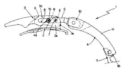
Clamp 1 comprises a supporting plate 2 fixed rigidly
to a first portion of the outer shell (not shown) of the
boot; a lock lever 3 hinged at one end 3a to supporting

CA 02395802 2002-07-26
4
plate 2; and a lock arm 4 having a first end 4a hinged so
as to slide freely along a central portion 3b of the body
of lock lever 3, as explained in detail later on, and a
second end 4b shaped to engage a known anchoring plate 5
fixed rigidly to a second portion (not shown) of the
outer shell of the boot.
With reference to Figures 1 and 2 in particular,
lock lever 3 is hinged to two flat parallel facing
brackets 2a projecting from supporting plate 2, so as to
l0 rotate freely about an axis A of rotation perpendicular
to the mid-plane M of the lever, and has a central
opening 6 extending from end 3a inwards of the body of
lock lever 3 and parallel to mid-plane M of the lever.
More specifically, end 3a of lock lever 3 is located
between the two flat brackets 2a on supporting plate 2,
and central opening 6 divides end 3a into two parallel
facing appendixes, each of which is hinged to a
respective bracket 2a by a cylindrical pin 7 extending
parallel to axis A through the body of bracket 2a and the
appendix.
With reference to Figures 1 and 2, at central
portion 3b of its body, lock lever 3 comprises two
contoured transverse slots 8, each formed in a
corresponding appendix of end 3a of lock lever 3. The two
contoured slots 8 are obviously located on opposite sides
of mid-plane M of the lever, and extend along the same
axis parallel to axis A, so as to be aligned with each
other.

CA 02395802 2002-07-26
With reference to Figures 1, 2 and 3, lock arm 4 is
divided into two longitudinal portions, to which
correspond the two ends 4a and 4b of lock arm 4.
The longitudinal portion comprising end 4a of the
5 arm - hereinafter indicated 9 - is shaped to engage and
slide along central opening 6 formed in the body of lock
lever 3 , and has on the end, i . a . at end 4a of the arm,
two cylindrical pins 10 extending on opposite sides of
the body of longitudinal portion 9, so as each to engage
l0 and slide along a respective contoured slot 8.
Both pins 10 extend coaxially with an axis B
parallel to the axis A of rotation of lock lever 3, so as
to slide freely, inside contoured slots 8, between a
first work position (Figures 1 and 2) in which pins 10
rest against the inner lateral surface portions of the
two contoured slots 8 closest to cylindrical pins 7, and
axis B is at a minimum distance from axis A; and a second
work position (Figure 3) in which pins 10 rest against
the inner lateral surface portions of the two contoured
slots 8 furthest from cylindrical pins 7, and axis B is
at a maximum distance from axis A. In addition, pins 10
are shaped to rotate freely about axis B inside the two
contoured slots 8, so as to allow lock arm 4 to rotate
freely with respect to lock lever 3.
In other words, end 4a of lock arm 4 is hinged to
slide freely along central portion 3b of the body of lock
lever 3, in which the two contoured slots 8 are formed.
With reference to Figures 1 and 3, the second

CA 02395802 2002-07-26
6
longitudinal portion of lock arm 4 comprising end 4b of
the arm - hereinafter indicated 11 - is shaped to permit
fast engagement and troublefree release of anchoring
plate 5 by the free end, and is preferably, though not
necessarily, connected to longitudinal portion 9 by a
known mechanical articulated joint 12 enabling the two
portions to move with respect to each other.
Operation of clamp 1 as described and illustrated is
easily deducible from the foregoing description with no
further explanation required.
The advantages of clamp 1 are obvious: the fact that
lock arm 4 is mounted to slide along central portion 3b
of the body of lock lever 3 greatly increases the forward
travel of the free end 4b of lock arm 4 when lock lever 3
is switched from the lock position to the release
position, thus simultaneously reducing the effort
required of the user on lock lever 3 to clamp the boot .
In the example shown, as lock lever 3 is rotated into the
lock position, pins 10 connecting lock arm 4 to the lever
move along respective contoured slots 8 towards the axis
A of rotation of lock lever 3, so as to reduce the arm
(i.e. the distance between axes A and B) of the resisting
force transmitted by lock arm 4 to the lever.
Clearly, changes may be made to the clamp as
described and illustrated herein without, however,
departing from the scope of the present invention.
In particular, in the variations shown in Figures 4,
5, 6 and 7, contoured slots 8 of lock lever 3 are so

CA 02395802 2002-07-26
7
shaped that pins 10 of lock arm 4 remain stationary as
they slide along the slots, and axis B does not lie in
the same plane through axis A at all times.
In particular, the path of axis B may be in the form
of a broken line (Figure 4), an arc (Figure 5), or a
straight line (Figures 6 and 7), but lying in a plane not
intersecting the axis A of rotation of lock lever 3.
Contoured slots 8 may also be shaped so that, when
axes A and B are a minimum distance apart, axis B is
1o closer than axis A to supporting plate 2, so as to
produce a torque by which to keep the lever in the lock
position.

Dessin représentatif
Une figure unique qui représente un dessin illustrant l'invention.
États administratifs

2024-08-01 : Dans le cadre de la transition vers les Brevets de nouvelle génération (BNG), la base de données sur les brevets canadiens (BDBC) contient désormais un Historique d'événement plus détaillé, qui reproduit le Journal des événements de notre nouvelle solution interne.

Veuillez noter que les événements débutant par « Inactive : » se réfèrent à des événements qui ne sont plus utilisés dans notre nouvelle solution interne.

Pour une meilleure compréhension de l'état de la demande ou brevet qui figure sur cette page, la rubrique Mise en garde , et les descriptions de Brevet , Historique d'événement , Taxes périodiques et Historique des paiements devraient être consultées.

Historique d'événement

Description Date
Inactive : CIB désactivée 2015-01-24
Inactive : CIB en 1re position 2014-09-29
Inactive : CIB attribuée 2014-09-29
Inactive : CIB expirée 2012-01-01
Le délai pour l'annulation est expiré 2006-07-26
Demande non rétablie avant l'échéance 2006-07-26
Inactive : CIB de MCD 2006-03-12
Réputée abandonnée - omission de répondre à un avis sur les taxes pour le maintien en état 2005-07-26
Lettre envoyée 2003-09-12
Inactive : Transfert individuel 2003-07-25
Modification reçue - modification volontaire 2003-07-25
Inactive : Correspondance - Formalités 2003-07-25
Demande publiée (accessible au public) 2003-01-27
Inactive : Page couverture publiée 2003-01-26
Inactive : CIB en 1re position 2002-10-11
Inactive : Lettre de courtoisie - Preuve 2002-09-17
Inactive : Certificat de dépôt - Sans RE (Anglais) 2002-09-11
Demande reçue - nationale ordinaire 2002-09-11

Historique d'abandonnement

Date d'abandonnement Raison Date de rétablissement
2005-07-26

Taxes périodiques

Le dernier paiement a été reçu le 2004-06-25

Avis : Si le paiement en totalité n'a pas été reçu au plus tard à la date indiquée, une taxe supplémentaire peut être imposée, soit une des taxes suivantes :

  • taxe de rétablissement ;
  • taxe pour paiement en souffrance ; ou
  • taxe additionnelle pour le renversement d'une péremption réputée.

Les taxes sur les brevets sont ajustées au 1er janvier de chaque année. Les montants ci-dessus sont les montants actuels s'ils sont reçus au plus tard le 31 décembre de l'année en cours.
Veuillez vous référer à la page web des taxes sur les brevets de l'OPIC pour voir tous les montants actuels des taxes.

Historique des taxes

Type de taxes Anniversaire Échéance Date payée
Taxe pour le dépôt - petite 2002-07-26
Enregistrement d'un document 2003-07-25
TM (demande, 2e anniv.) - petite 02 2004-07-26 2004-06-25
Titulaires au dossier

Les titulaires actuels et antérieures au dossier sont affichés en ordre alphabétique.

Titulaires actuels au dossier
TEKNOSTAMPI S.R.L.
Titulaires antérieures au dossier
REMIGIO BERLESE
Les propriétaires antérieurs qui ne figurent pas dans la liste des « Propriétaires au dossier » apparaîtront dans d'autres documents au dossier.
Documents

Pour visionner les fichiers sélectionnés, entrer le code reCAPTCHA :


Pour visualiser une image, cliquer sur un lien dans la colonne description du document (Temporairement non-disponible). Pour télécharger l'image (les images), cliquer l'une ou plusieurs cases à cocher dans la première colonne et ensuite cliquer sur le bouton "Télécharger sélection en format PDF (archive Zip)" ou le bouton "Télécharger sélection (en un fichier PDF fusionné)".

Liste des documents de brevet publiés et non publiés sur la BDBC .

Si vous avez des difficultés à accéder au contenu, veuillez communiquer avec le Centre de services à la clientèle au 1-866-997-1936, ou envoyer un courriel au Centre de service à la clientèle de l'OPIC.

({010=Tous les documents, 020=Au moment du dépôt, 030=Au moment de la mise à la disponibilité du public, 040=À la délivrance, 050=Examen, 060=Correspondance reçue, 070=Divers, 080=Correspondance envoyée, 090=Paiement})


Description du
Document 
Date
(aaaa-mm-jj) 
Nombre de pages   Taille de l'image (Ko) 
Dessin représentatif 2002-10-14 1 8
Description 2002-07-25 7 244
Revendications 2002-07-25 2 65
Abrégé 2002-07-25 1 13
Dessins 2002-07-25 3 38
Certificat de dépôt (anglais) 2002-09-10 1 162
Demande de preuve ou de transfert manquant 2003-07-28 1 102
Courtoisie - Certificat d'enregistrement (document(s) connexe(s)) 2003-09-11 1 106
Rappel de taxe de maintien due 2004-03-28 1 110
Courtoisie - Lettre d'abandon (taxe de maintien en état) 2005-09-19 1 173
Correspondance 2002-09-10 1 25
Correspondance 2003-07-24 1 37
Taxes 2004-06-24 1 28