Sélection de la langue

Search

Sommaire du brevet 2395932 

Énoncé de désistement de responsabilité concernant l'information provenant de tiers

Une partie des informations de ce site Web a été fournie par des sources externes. Le gouvernement du Canada n'assume aucune responsabilité concernant la précision, l'actualité ou la fiabilité des informations fournies par les sources externes. Les utilisateurs qui désirent employer cette information devraient consulter directement la source des informations. Le contenu fourni par les sources externes n'est pas assujetti aux exigences sur les langues officielles, la protection des renseignements personnels et l'accessibilité.

Disponibilité de l'Abrégé et des Revendications

L'apparition de différences dans le texte et l'image des Revendications et de l'Abrégé dépend du moment auquel le document est publié. Les textes des Revendications et de l'Abrégé sont affichés :

  • lorsque la demande peut être examinée par le public;
  • lorsque le brevet est émis (délivrance).
(12) Brevet: (11) CA 2395932
(54) Titre français: DISPOSITIF POUR UNE MACHINE DE FLOTTATION
(54) Titre anglais: DEVICE FOR A FLOTATION MACHINE
Statut: Périmé et au-delà du délai pour l’annulation
Données bibliographiques
(51) Classification internationale des brevets (CIB):
  • B03D 01/16 (2006.01)
  • B03D 01/20 (2006.01)
(72) Inventeurs :
  • BELKE, JEFFREY (Australie)
(73) Titulaires :
  • OUTOTEC OYJ
(71) Demandeurs :
  • OUTOTEC OYJ (Finlande)
(74) Agent: NORTON ROSE FULBRIGHT CANADA LLP/S.E.N.C.R.L., S.R.L.
(74) Co-agent:
(45) Délivré: 2010-06-15
(86) Date de dépôt PCT: 2000-12-20
(87) Mise à la disponibilité du public: 2001-07-12
Requête d'examen: 2005-12-12
Licence disponible: S.O.
Cédé au domaine public: S.O.
(25) Langue des documents déposés: Anglais

Traité de coopération en matière de brevets (PCT): Oui
(86) Numéro de la demande PCT: PCT/FI2000/001125
(87) Numéro de publication internationale PCT: FI2000001125
(85) Entrée nationale: 2002-06-28

(30) Données de priorité de la demande:
Numéro de la demande Pays / territoire Date
19992816 (Finlande) 1999-12-30

Abrégés

Abrégé français

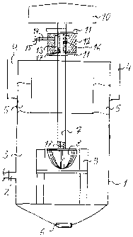
L'invention concerne un dispositif pour une machine de flottation dans laquelle un arbre d'entraînement, prévu pour mélanger une barbotine et transporter de l'air est entraîné par un mécanisme d'entraînement et l'arbre d'entraînement est pourvu d'un ensemble de palier et est, au moins partiellement, creux à l'intérieur pour transférer de l'air à un rotor. Selon la présente invention, l'arbre d'entraînement (7) est pourvu d'au moins un palier (11) dans un logement séparé d'au moins un élément (12) formant une chambre de transfert d'air (13) autour de l'arbre d'entraînement (7). En outre, l'arbre d'entraînement (7) comporte au moins une ouverture (16) pour créer un raccordement continu entre la chambre de transfert d'air (16) et l'intérieur (17) de l'arbre d'entraînement (7).


Abrégé anglais


The invention relates to a device for a flotation machine in which a drive
shaft for mixing slurry and transporting air is driven by a drive arrangement
and the drive shaft is provided with a bearing assembly and the drive shaft is
at least partly hollow in the interior for transferring air to a rotor.
According to the invention the drive shaft (7) is provided with at least one
bearing (11) in a housing separated from at least one element (12) forming an
air transfer chamber (13) around the drive shaft (7). Further, the drive shaft
(7) has at least one opening (16) in order to create an essentially continuous
connection between the air transfer chamber (16) and the interior (17) of the
drive shaft (7).

Revendications

Note : Les revendications sont présentées dans la langue officielle dans laquelle elles ont été soumises.


6
CLAIMS
1. Device for a flotation machine in which a drive shaft for mixing slurry and
transporting air is driven by a drive arrangement and the drive shaft is
provided
with a bearing assembly and the drive shaft is at least partly hollow in the
interior for transferring air to a rotor, characterised in that the drive
shaft (7) is
provided with at least two bearings (11) in a housing between which bearings
(11) and separately installed from the bearings (11) there is positioned at
least
one element (12) forming an air transfer chamber (13) around the drive shaft
(7), and the drive shaft (7) has at least one opening (16) in order to create
an
essentially continuous connection between the air transfer chamber (16) and
the interior (17) of the drive shaft (7).
2. Device according to the claim 1, characterised in that the element (12)
forming the air transfer chamber (13) is installed in a non-fixed position to
the
drive shaft (7).
3. Device according to the claim 1, characterised in that the element (12)
forming the air transfer chamber (13) is fixed to the drive shaft (7).
4. Device according to any of the proceeding claims, characterised in that the
element (12) is removable and independent from the bearing housings (11).
5. Device according to the claim 1, characterised in that the drive shaft (7)
has
one opening (16) for the essentially continuous connection between the air
transfer chamber (16) and the interior (17) of the drive shaft (7).

Description

Note : Les descriptions sont présentées dans la langue officielle dans laquelle elles ont été soumises.


CA 02395932 2002-06-28
V1~'O 01/49388 PCT/FI00/01125
1
DEVICE FOR A FLOTATION MACHINE
The invention relates to a device for a flotation machine, particularly to a
bearing assembly of a drive shaft of the flotation machine. The bearing assem-
bly contains one or more bearings and an air transfer chamber separated from
the bearing or bearings.
In a flotation machine a drive shaft is used to support the submerged mecha-
nism which mixes slurry as well as for feeding air to the flotation machine.
Then
the drive shaft is hollow so that air is transferred inside the drive shaft to
the
rotor installed on the end of the drive shaft. By mixing and air feeding a
part of
the slurry containing for instance desired valuable metal or minerals is
flotated
and this flotated part of the slurry is removed from the flotation cell as an
overflow via a froth lip in the upper part of the flotation cell. The non-
flotated
part of the slurry is removed from the flotation cell for instance through a
bottom outlet of the flotation cell. Slurry is fed into the flotation cell in
an essen-
tially continuous fashion so that slurry to be fed will replace flotated and
non-flotated parts removed from the flotation cell.
The drive shaft of the flotation machine has a bearing housing which is
usually
manufactured as a single casting. The casting of the bearing housing is then
machined out to take the bearings and lip seals so that the air transfer
chamber
is between the bearings and the lip seals in the same casting. Thus the
bearings, the lip seals and the air transfer chamber are combined with each
other. When a bearing or a lip seal is needed to be changed the whole combi-
nation of the bearings, the lips seals and the air transfer chamber have to be
removed from the drive shaft. Further, because the assembly of the bearing
housing is difficult and requires a person well trained in the art, the mainte-
nance of the bearing assembly will be expensive and takes time.

CA 02395932 2002-06-28
VVO 01/49388 PCT/FI00/01125
2
The object of the present invention is to eliminate some drawbacks of the
prior
art and to achieve a new device for the bearing assembly of the drive shaft in
a
flotation machine which device is simpler as its construction and easier and
cheaper to maintain. The essential features of the invention are enlisted in
the
enclosed claims.
According to the invention a drive shaft for a flotation machine is used for
mixing and transporting the air to a rotor in the flotation cell of the
flotation
machine. The drive shaft is advantageously provided with a rotor at that end
of
the drive shaft which is submerged in the slurry in the flotation cell. At the
end
or in the vicinity of the end of the drive shaft opposite to the end submerged
in
the slurry the drive shaft is connected with a drive arrangement. The drive
shaft
is driven by the drive arrangement for mixing the slurry in the flotation
cell. Air to
be used in the flotation process for forming froth in the flotation cell is
fed
through the drive shaft so that air is dispersed into slurry via the rotor
blades.
The drive shaft is thus hollow in its interior at least in that part where air
is trans-
ported to the rotor. In order to stabilise the drive shaft for slurry mixing
the drive
shaft is provided with at least one bearing, advantageously in the vicinity of
the
drive arrangement.
In the preferred embodiment of the invention the drive shaft of the flotation
machine is provided with two bearings installed in the vicinity of the drive
arrangement. The bearings have separate bearing housings. Between these
bearing housings a separate air transfer chamber is installed around the drive
shaft. The air transfer chamber is used to feed air from an external source to
the interior of the drive shaft. The air transfer chamber is formed so that
concentrically around the drive shaft there is installed at least one element
which is sealed around the drive shaft at both ends by seals so that the inner
diameter of the element is essentially the same as the outer diameter of the
drive shaft in the ends or in the vicinity of the ends of the element. Space
for air
in the air transfer chamber is formed so that the inner diameter of the
element is

CA 02395932 2002-06-28
V1~'O 01/49388 PCT/FI00/01125
3
greater than the outer diameter of the drive shaft on the area between the
ends
of the element. The air transfer chamber is provided with at least one connect-
ing member which has connection with the external source of air. Because the
air transfer chamber is separated from the bearings the air transfer chamber
is
removable and independent from the use or lifetime of the bearing housings.
For preferred air feeding in accordance with the invention, the drive shaft is
provided with at least one opening between the external surface of the drive
shaft and the interior of the drive shaft. This opening is so positioned and
shaped that the opening has contact with the air transfer chamber essentially
continuously in order to create a closed air feeding from the external air
source
to the rotor of the flotation machine. Thus air to be fed to the rotor is
first flowed
into the air transfer chamber and, thereafter, into the interior of the drive
shaft
and further through the rotor as dispersed bubbles into the slurry in the
flotation
machine.
The element forming the air transfer chamber is preferably installed in a
non-fixed position to the drive shaft so that the element can be rotated
between
0 and 360 degrees around the drive shaft. In one embodiment the element can
also be installed so that the element is rotated with the drive shaft and the
opening between the air transfer chamber and the interior of the drive shaft
is
kept essentially at the same position to the air transfer chamber. Then the
opening can be a relatively small hole in the drive shaft, and the air
transfer
chamber can be shaped smaller and narrower, like a ring with a connecting
member for feeding air into the interior of the drive shaft. Independent from
the
shape of the opening the opening has to be such that the opening allows a
continuous air flow from the air transfer chamber into the interior of the
drive
shaft.
Using the device of the invention the initial assembly of the bearings is
easier
and cost effective and the maintenance is much easier to the prior art because

CA 02395932 2002-06-28
V1~'O 01/49388 PCT/FI00/01125
4
the bearings and the air transfer chamber can be installed and changed
separately. This also means that the bearing housing and the air transfer
chamber can be rotated between 0 and 360 degrees around the drive shaft and
thus advantageously the air transfer chamber can be installed in different
positions to the bearings. The bearings can also be rotated around the drive
shaft when installed in order to ensure that the bearing clearances are
correct.
The device of the invention eliminates the use of withdrawal sleeves and
further
simplifies the bearing assembly. Naturally, it is also possible to install at
least
one bearing housing and the air transfer chamber so that the bearing housing
and the air transfer chamber are not able to rotate around the drive shaft and
thus the bearing housing and the air transfer chamber are fixed to the drive
shaft.
The invention is described in more details in the following referring to the
enclosed drawing which illustrates one preferred embodiment of the invention
as a partly-cut schematic side-view.
According to the drawing the flotation machine contains a flotation cell 1
with a
feeding inlet 2 for slurry 3 to be treated, an over lip 4 for froth 5 created
in the
flotation cell 1 and a bottom outlet 6 for non-flotatable material. A drive
shaft 7
is partly submerged in the slurry 3. The drive shaft 7 provided with a rotor 8
in
the end submerged in the slurry 3 is used for mixing and transporting air to
the
rotor 8 of the flotation cell 1. Further, the rotor 8 is surrounded by a
stator 9
installed in the flotation cell 1. The drive shaft 7 is driven by a drive
arrange-
ment 10 installed in the end of the drive shaft 7 opposite to the end
submerged
in the slurry 3. The drive shaft 7 is provided with two bearings 11 installed
around the drive shaft 7 close to the drive arrangement 10. Between the
bearings 11 there is installed an element 12 which forms a removable air trans
fer chamber 13 around the drive shaft 7. The drive shaft 7 is hollow in its
interior
between the air transfer chamber 13 and the rotor 8.

CA 02395932 2002-06-28
V1~'O 01/49388 PCT/FI00/01125
For air flowing from an external air source to the rotor 8 the element 12 for
the
air transfer chamber 13 is provided with at least one connecting member 14
which creates a connection between a connector 15 from an external air source
and the air transfer chamber 13. Further, the drive shaft 7 is provided with
at
5 least one opening 16 between the air transfer chamber 13 and the interior 17
of
the drive shaft 7. The opening 16 is so shaped that an essentially continuous
air flow from the air transfer chamber 13 to the interior 17 of the drive
shaft 7 is
created.
During the operation of the flotation machine the drive shaft 7 is rotated by
the
drive arrangement 10. Then the opening 16 between the air transfer chamber
13 and the interior 17 of the drive shaft 7 is rotated, but a continuous air
flow
through the opening 16 is maintained.

Dessin représentatif
Une figure unique qui représente un dessin illustrant l'invention.
États administratifs

2024-08-01 : Dans le cadre de la transition vers les Brevets de nouvelle génération (BNG), la base de données sur les brevets canadiens (BDBC) contient désormais un Historique d'événement plus détaillé, qui reproduit le Journal des événements de notre nouvelle solution interne.

Veuillez noter que les événements débutant par « Inactive : » se réfèrent à des événements qui ne sont plus utilisés dans notre nouvelle solution interne.

Pour une meilleure compréhension de l'état de la demande ou brevet qui figure sur cette page, la rubrique Mise en garde , et les descriptions de Brevet , Historique d'événement , Taxes périodiques et Historique des paiements devraient être consultées.

Historique d'événement

Description Date
Inactive : CIB expirée 2022-01-01
Le délai pour l'annulation est expiré 2015-12-21
Lettre envoyée 2014-12-22
Accordé par délivrance 2010-06-15
Inactive : Page couverture publiée 2010-06-14
Inactive : Taxe finale reçue 2010-03-25
Préoctroi 2010-03-25
Lettre envoyée 2010-01-11
Un avis d'acceptation est envoyé 2010-01-11
Inactive : Approuvée aux fins d'acceptation (AFA) 2010-01-04
Modification reçue - modification volontaire 2009-10-20
Lettre envoyée 2009-08-24
Inactive : Transfert individuel 2009-07-07
Inactive : Dem. de l'examinateur par.30(2) Règles 2009-04-20
Inactive : CIB de MCD 2006-03-12
Lettre envoyée 2006-01-06
Exigences pour une requête d'examen - jugée conforme 2005-12-12
Toutes les exigences pour l'examen - jugée conforme 2005-12-12
Modification reçue - modification volontaire 2005-12-12
Requête d'examen reçue 2005-12-12
Lettre envoyée 2003-02-17
Inactive : Transfert individuel 2002-12-13
Inactive : CIB enlevée 2002-12-03
Inactive : CIB en 1re position 2002-12-03
Inactive : Page couverture publiée 2002-11-27
Inactive : Lettre de courtoisie - Preuve 2002-11-26
Inactive : Notice - Entrée phase nat. - Pas de RE 2002-11-25
Demande reçue - PCT 2002-09-11
Exigences pour l'entrée dans la phase nationale - jugée conforme 2002-06-28
Demande publiée (accessible au public) 2001-07-12

Historique d'abandonnement

Il n'y a pas d'historique d'abandonnement

Taxes périodiques

Le dernier paiement a été reçu le 2009-11-27

Avis : Si le paiement en totalité n'a pas été reçu au plus tard à la date indiquée, une taxe supplémentaire peut être imposée, soit une des taxes suivantes :

  • taxe de rétablissement ;
  • taxe pour paiement en souffrance ; ou
  • taxe additionnelle pour le renversement d'une péremption réputée.

Les taxes sur les brevets sont ajustées au 1er janvier de chaque année. Les montants ci-dessus sont les montants actuels s'ils sont reçus au plus tard le 31 décembre de l'année en cours.
Veuillez vous référer à la page web des taxes sur les brevets de l'OPIC pour voir tous les montants actuels des taxes.

Titulaires au dossier

Les titulaires actuels et antérieures au dossier sont affichés en ordre alphabétique.

Titulaires actuels au dossier
OUTOTEC OYJ
Titulaires antérieures au dossier
JEFFREY BELKE
Les propriétaires antérieurs qui ne figurent pas dans la liste des « Propriétaires au dossier » apparaîtront dans d'autres documents au dossier.
Documents

Pour visionner les fichiers sélectionnés, entrer le code reCAPTCHA :


Pour visualiser une image, cliquer sur un lien dans la colonne description du document. Pour télécharger l'image (les images), cliquer l'une ou plusieurs cases à cocher dans la première colonne et ensuite cliquer sur le bouton "Télécharger sélection en format PDF (archive Zip)" ou le bouton "Télécharger sélection (en un fichier PDF fusionné)".

Liste des documents de brevet publiés et non publiés sur la BDBC .

Si vous avez des difficultés à accéder au contenu, veuillez communiquer avec le Centre de services à la clientèle au 1-866-997-1936, ou envoyer un courriel au Centre de service à la clientèle de l'OPIC.


Description du
Document 
Date
(aaaa-mm-jj) 
Nombre de pages   Taille de l'image (Ko) 
Dessin représentatif 2002-06-27 1 15
Revendications 2002-06-27 1 42
Dessins 2002-06-27 1 16
Description 2002-06-27 5 210
Abrégé 2002-06-27 2 60
Revendications 2009-10-19 1 31
Dessin représentatif 2010-05-16 1 7
Avis d'entree dans la phase nationale 2002-11-24 1 189
Courtoisie - Certificat d'enregistrement (document(s) connexe(s)) 2003-02-16 1 107
Rappel - requête d'examen 2005-08-22 1 116
Accusé de réception de la requête d'examen 2006-01-05 1 176
Courtoisie - Certificat d'enregistrement (document(s) connexe(s)) 2009-08-23 1 121
Avis du commissaire - Demande jugée acceptable 2010-01-10 1 162
Avis concernant la taxe de maintien 2015-02-01 1 170
PCT 2002-06-27 8 341
Correspondance 2002-11-24 1 24
Correspondance 2010-03-24 2 65