Note : Les descriptions sont présentées dans la langue officielle dans laquelle elles ont été soumises.
~ CA 02396019 2002-07-29
US-Version/WER
Patent-Treuhand-Gesellschaft
fur elektrische Gliihlampen mbH., Munich
LED-based planar light source
Technical Field
The invention relates to an LED-based planar light source in
accordance with the preamble of Claim 1. In particular, this is a
planar light source for LCD backlighting, or else for other
applications, which is, in particular, fully colour-capable and,
moreover, has a high luminance.
Background Art
JP-A 7-176794 has already disclosed an LED-based planar light
source in the case of which a blue LED produces white light on a
planar surface by means of partial conversion by a yellow-orange
phosphor. However, this simple complementary mixing does not
2 0 permit good colour rendering.
A more complicated concept with better colour rendering is three
colour mixing. In this case, the primary colours red-green-blue
(RGB) are used to produce white by mixing. Use can be made here
either of a blue LED for the partial conversion of two phosphors
which emit red and green (WO 00/33390), or of a UV-emitting LED
which excites three phosphors which respectively have their
emission in the red, green and blue - see WO 97/48138. Examples
are line emitters such as YOB:Ce,Tb (green) and YOS:Eu (red).
However, this requires a relatively shortwave emission (UV region
< 370 nm) in order to be able to achieve high quantum yields. This
conditions the use of sapphire substrates for the UV-LEDs which
are very expensive. On the other hand, if use is made of a UV-LED
based on the cheaper SiC substrates, it is necessary to accept an
emission in the region of 380 to 420 nm, and this renders
difficult or impossible the use of line emitters in the green and
red. This leads to absorption problems in the case of blue
phosphors.
' ~ ' ~ CA 02396019 2002-07-29
- 2 -
_ A specific problem here is, moreover, the additional absorption
loss of blue radiation owing to the broadband nature of the
absorption of the red- and green-emitting phosphors. Taken
altogether, this leads to clear restrictions in the setting of the
light colour and/or the luminance efficiency.
Disclosure of the Invention
It is an object of the present invention to provide a fully
colour-capable planar light source utilizing the colour mixing
principle, the radiation from UV-emitting diodes arranged in a
planar fashion being converted into light of longer wavelength by
means of conversion by at least one UV-absorbing phosphor, and
this light being mixed with a blue component, which achieves a
1 5 high luminance efficiency and yet is economical.
This object is achieved by means of the following features: the
radiation of the UV diodes is absorbed by the at least one
phosphor while the blue component is provided by at least one
2 0 blue-emitting LED.
Particularly advantageous refinements are to be found in the
dependent claims.
2 5 Planar light sources as described in outline in US-A 5 619 351,
for example, are frequently used for backlighting of LCDs. In this
case, a compact fluorescent lamp has predominantly been used to
date as light source. This requires a high supply voltage and
creates problems with electromagnetic compatibility, for which
3 0 reason it is worth attempting to replace the lamps by LEDs.
According to the invention, a planar light source which is fully
colour-capable is provided by utilizing the RGB principle, the
radiation of a multiplicity of UV diodes arranged in a planar
3 5 fashion being converted into light of longer wavelength by means
of conversion by phosphors. Here, the term UV means the region of
300 to 920 nm. The radiation of the UV diodes is absorbed solely
by green-emitting phosphors (preferably with a peak emission
wavelength between 510 and 560 nm, for example SrAl~O,~: Eu'' or Eu''-
~ ~ CA 02396019 2002-07-29
- 3 -
based thiogallates) and red-emitting phosphors (preferably with a
peak emission wavelength of more than 590 nm up to 690 nm, for
example Sr2Si5N8:Eu2') while the blue component (preferably with a
peak emission wavelength between 430 and 490 nm) is provided by
blue-emitting LEDs. This principle is surprising per se, because
at first glance it appears substantially more complicated than the
known solutions, since more LEDs are used, and the latter must be
driven in a fashion separated at least into two groups (UV-LEDs
and blue LEDs).
However, it is to be borne in mind in this case that the price of
blue LEDs is more favourable than the price of UV-LEDs, and that,
on the other hand, it is possible to economize on a few UV-LEDs .
Moreover, a spatial separation of the blue LEDs from the red and
green phosphors provides an elegant possibility of avoiding
partial absorption of the blue radiation of the LEDs by these RG
phosphors. Consequently, a more efficient light source can be
created at lower cost. Finally, particular advantages are
associated with the fact that instead of an expensive UV-LED on a
2 0 sapphire substrate with an emission peak below 380 nm it is
possible to use as UV-LED a cheap GaN-based LED (preferably doped
with In and/or A1) on an SiC substrate with an emission peak
between 380 and 420 nm. The point is that a slight overlap between
the emission spectrum of the UV-LED and an absorption spectrum of,
2 5 for example, a blue-emitting phosphor plays no role at all in the
concept according to the invention, while it yields poorer results
in the case of the conversion of UV into blue (> 380 nm). This
energy spacing (overlap) between excitation source and absorption
curve of the phosphor no longer plays an important role with
30 reference to the red- or green-emitting phosphor which, in some
circumstances, both use the same activator, in particular Eu. In
general, it emerges that the absorption problem no longer plays a
role in the case of broadband-emitting phosphors, in particular
starting from approximately 490 nm peak emission. The concept of
35 the present invention can therefore not only be applied in the
case of RGB mixtures, but also includes the application of
additional phosphors. A further application is, finally, the
production of a white light source on the simpler principle of
blue-yellow mixing, in accordance with the first white-emitting
~ ~ CA 02396019 2002-07-29
- 4 -
LEDs of the prior art. In this case, the blue component is
provided here by the primary emission of a number of blue LEDs,
and the yellow component is provided by the yellow emission of a
suitable phosphor excited by a number of UV-LEDs. A further
application is, moreover, the provision of a planar light source
of specific colour, it being possible for this special colour to
be produced by mixing a blue and a further component. In this
case, the blue component is again provided by the primary emission
of a number of blue LEDs, and the further components are provided
by the emission of a (or else a plurality of further) suitable
phosphor excited by a number of UV-LEDs, the desired colour
resulting from the mixing of the emissions. Concrete examples for
such phosphors have, for example, peak emissions in the blue-green
(for example Sr6BP50~o:Euz', Sr4A1140~5:EU'') or green-yellow or yellow
( for example Sr~SiSNa: Ce", (Sr, Ba) Si04: Eu'+) or yellow-orange ( for
example Ca~Si~,N,3:EU'', Cal~SAl,,Si~N1'':Eu'') .
In principle, the RG phosphors can be placed directly on the
individual UV-LEDs. It is advantageous for the red- and green-
2 0 emitting phosphors to be applied to, or implemented inside, on an
optical conductor fitted at a spacing from the UV diodes, or on a
transparent plate acting like an optical conductor, because the
spacing yields a better uniformity of the planar emission. The
number of the blue-emitting LEDs per assembly is at most equal to
2 5 the number of the UV diodes. In the case when the blue-emitting
LEDs are arranged in a planar fashion, it corresponds
approximately to the number of the UV diodes (50 to 100,
correspondingly).
30 A substantial reduction in the number of the blue-emitting LEDs
(typically by 10 to 40~) can be achieved when the blue-emitting
LEDs are arranged in rows at the edge of the surface fitted with
the UV-LEDs. They are then launched into the forward emission of
the surface by means of suitable techniques known per se. In the
35 simplest case, a single row is arranged laterally at an edge strip
next to an array of UV diodes. It is typical in this case for the
launching to be achieved by means of a wedge-shaped (or else flat)
plate which has punctiform etchings of different density such that
a uniform brightness of the surface is achieved overall.
~ ' CA 02396019 2002-07-29
- 5 -
However, this technique can be modified to the effect that a
plurality of edge strips with LEDs arranged in rows are fitted. In
the simplest case, therefore, two rows are arranged laterally next
to edges of a surface of UV diodes. Proceeding from a rectangular
surface, the two rows can be at a right angle to one another or be
arranged parallel to one another at opposite edges.
Brief Description of the Drawings
The invention is to be explained in more detail below with the aid
of a plurality of exemplary embodiments. In the drawing:
Figure 1 shows a planar light source, in section;
Figure 2 shows an emission and reflection spectrum of a green-
emitting phosphor:
Figure 3 shows an emission and reflection spectrum of a red-
emitting phosphor;
Figure 4 shows an emission spectrum of a lighting unit according
2 0 to the invention, compared with a conventional
lighting unit; and
Figure 5 shows an emission spectrum of a lighting unit according
to the invention, with and without a dedicated blue
component.
Best Mode for Carrying Out the Invention
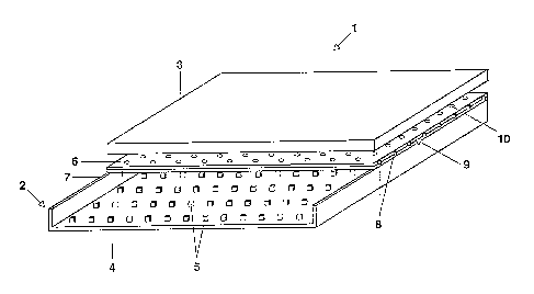
Figure 1 shows an LCD display device 1 with a planar light source
2 for backlighting an LCD display 3. An additionally present
3 0 rectangular housing has been omitted for the sake of simplicity,
as is true of customary additional components such as polarization
and colour filters and drive units (for example TFTs). The planar
light source 2 comprises a basic body 4 on which an array of UV
diodes 5 are arranged spaced apart uniformly in the shape of a
3 5 raster. An optical conductor plate 6, which can be wedge-shaped
(no wedge shape is shown) , is spaced apart in front of the basic
body 4 and mounted parallel thereto. The plate 6 has output means
for the uniform upward emission of laterally irradiated light. In
the case of a wedge-shaped plate, these coupling centres can be
CA 02396019 2002-07-29
- 6 -
distributed uniformly on the surface of the plate. In the case of
a plane-parallel plate, the arrangement of the centres is
nonuniform, since only so is it possible for the blue light to be
emitted in a fashion distributed uniformly over the surface of the
plate. On the side facing the UV-LEDs, the plate 6 is provided
with a coating 7 which comprises a mixture of two phosphors with
green and red emission. The UV radiation of the diodes 5 (InGaN
with 390 nm peak emission wavelength) is converted here virtually
completely into red and green light.
Fitted laterally at an edge of the transparent plate 6 (made from
glass, plastic, PET or the like) is a row of blue-emitting LEDs 8
whose light is emitted into the plate 6 and is output forwards by
the coupling centres 10 on the surface of the plate 6 (for example
1 5 etchings on the front side of the plate or microprisms, or the
like). The blue light mixes with the green and red light from the
coating 7 to form white.
The two types of LEDs 5, 8 are driven separately (not illustrated)
2 0 and can thereby be set to a desired colour location, or else
corrected.
To provide a better understanding of the mode of operation and of
the advantages, Figure 2 shows the emission spectrum and
2 5 reflection spectrum of an advantageously employed green-emitting
phosphor SrAlzO~:Euz' with emission peak wavelength at 524 nm. At
the same time, the reflection spectrum also shows the absorption
behaviour in accordance with the known relationship R(~) - 100 -
A (~) where R = reflection and A = absorption. Furthermore, the
3 0 emission spectrum of a blue-emitting phosphor (BaMgAl1~01i:Eu, known
as BAM) typically used in the prior art is illustrated in the
reflection spectrum. It may clearly be seen here that the blue
radiation of the BAM would be largely absorbed by the green
phosphor. This problem is completely avoided by means of the
3 5 concept of the present invention.
Similarly, Figure 3 shows the emission spectrum and reflection
spectrum of an advantageously employed red-emitting phosphor
Sr~Si~,N~:Eu2' with emission peak wavelength at 623 nrn. Here, as
' CA 02396019 2002-07-29
_ 7 _
well, a blue-emitting phosphor (BAM) typically used in the prior
art is illustrated in the reflection spectrum. In this case, as
well, a partial absorption of the blue radiation by the red
phosphor would be active.
Figure 4 shows the emission spectrum of an inventive planar light
source with a UV diode array, the conversion of the UV radiation
by a previously known phosphor mixture of RGB phosphors as
described above being illustrated (1) for the purposes of
comparison. According to the invention, a row of blue-emitting
LEDs is used (2) instead of the blue phosphor. This arrangement
shows a rise in efficiency by 30~ (because absorbing mechanisms
are eliminated), 10~ of the number of the UV-LEDs (originally 50)
being dispensed with. Use is made, instead, of a row of blue LEDs
(10 items).
Figure 5 shows the emission spectrum of an inventive planar light
source with a UV diode array (peak wavelength 905 m), the
conversion of the UV radiation by a previously known phosphor
2 0 mixture of RG phosphors as described above being illustrated (1)
for the purposes of comparison. According to the invention, a row
of blue-emitting LEDs (peak wavelength 960 m) is coupled in (2).
This arrangement is set up such that the resulting spectrum is in
the vicinity of the white point. For this purpose, the proportion
2 5 of the blue radiation must be substantially greater compared to
the green and red proportions, in order to take account of the
sensitivity of the human eye, which is lower in the blue.
A particularly advantageous utilization of the novel mixing
30 principle consists in making an entirely conscious selection as
far as possible of a red phosphor and also of a green phosphor
which absorbs in each case at least a portion of the blue primary
radiation (LED). At least one of the phosphors advantageously
absorbs the blue primary radiation as completely as possible.
35 Absorption of the blue radiation is avoided nevertheless owing to
the fact that the admixture of the blue radiation in the beam path
is performed only after the conversion. A portion of the blue
radiation which is deflected in the forward direction is, however,
backscattered at the boundary surfaces, consequently traverses the
~
CA 02396019 2002-07-29
phosphor layer and is converted there at least partially and
partially re-emitted in the forward direction. This actually lost
portion of the blue radiation is therefore added to the useful
radiation, whereas without the possibility of absorption by the
red phosphor, and also to a lesser extent by the green phosphor,
it could not be used and would, rather, lead to heating up the
light source undesirably.
The same concept can also, of course, be implemented in the case
of a yellow phosphor.