Note : Les descriptions sont présentées dans la langue officielle dans laquelle elles ont été soumises.
CA 02396692 2002-08-02
DUAL DYNAMIC ROTARY SEAL
Background of Invention
Field of the Invention
(0001 ] The invention relates generally to seals used with roller cone drill
bits.
lUlore specifically, the invention relates to rotary seals that include more
than
one dynamic sealing surface for maintaining lubrication in roller cone drill
bits.
Background Art
[0002] Drill bits are commonly used in, for example, the oil and gas
exploration
industry for drilling wells in earth formations. One type of drill bit
commonly
used in the industry is the roller cone drill bit. Roller cone drill bits
generally
comprise a bit body connected to a drill string or bottom hole assembly (BHA).
Roller cone drill bits typically include a plurality of roller cones rotatably
attached to the bit body. The roller cones are generally mounted on steel
journals integral with the bit body at its lower end. The roller cones further
comprise a plurality of cutting elements disposed on each of the plurality of
roller cones. The cutting elements may comprise, for example, inserts (formed
from, for example, polycrystalline diamond, boron nitride, and the like)
and/or
milled steel teeth that are coated with appropriate hardfacing materials.
[0003] When drilling an earth formation, the roller cone drill bit is rotated
in a
wellbore, and each roller cone contacts the bottom of the wellbore being
drilled
and subsequently rotates with respect to the drill bit body. Drilling
generally
continues until, for example, a bit change is required because of a change in
formation type is encountered in the wellbore or because the drill bit is worn
and/or damaged. High temperatures, high pressures, tough, abrasive
formations, and other factors all contribute to drill bit wear and failure.
(0004] When a drill bit wears out or fails as the wellbore is being drilled,
it is
necessary to remove the BHA from the well so that the drill bit may be
replaced. The amount of time required to make a bit replacement trip produces
1
CA 02396692 2002-08-02
doumtime in drilling operations. The amount of downtime may be significant,
for example, when tripping in and out of relatively deep wells. Downtime can
add to the cost of completing a well and is a particular problem in offshore
operations where costs are significantly higher. It is therefore desirable to
maximize the service life of a drill bit in order to avoid rig downtime.
[0005] One reason for the failure of a roller cone drill bit is the wear that
occurs
on the journal bearings that support the roller cones. The journal bearings
may
be friction-type or roller-type bearings, and the journal bearings are
subjected
to high loads, high pressures, high temperatures, and exposure to abrasive
particles originating from the formation being drilled. The journal bearings
are
typically lubricated with grease adapted to withstand tough drilling
environments, and such lubricants are an important element in the life of a
drill
bit.
[0006] Lubricants are retained by a journal bearing seal, which is typically
an
O-ring type seal. The seal is typically located in a seal groove formed on an
interior surface of a roller cone. The seal generally includes a static seal
surface adapted to form a static seal with the interior surface of the roller
cone
and a dynamic seal surface adapted to form a dynamic seal with the journal
upon which the roller cone is rotatably mounted. The seal must endure a range
of temperature and pressure conditions during the operation of the drill bit
to
prevent lubricants from escaping and/or contaminants from entering the journal
bearing. Elastomer seals known in the art are conventionally formed from a
single type of rubber or elastomeric material, and are generally formed having
identically configured dynamic and static seal surfaces with a generally
regular
cross section.
[0007] The rubber or elastomeric material selected to form the seal for the
journal bearings has particular hardness, modulus of elasticity, wear
resistance,
temperature stability, and coefficient of friction, among other properties.
Additionally, the particular geometric configuration of the seal surfaces
produces a selected amount of seal deflection that defines the degree of
contact
2
CA 02396692 2002-08-02
pressure or "squeeze" applied by the dynamic and static seal surfaces against
respective journal bearing and roller cone surfaces.
[0008] The wear, temperature, and contact pressures encountered at the
dynamic seal surface are different than those encountered at the static seal
surface. Therefore, the type of seal material and seal geometry that is
ultimately selected to form both seal surfaces represents a compromise between
satisfying the operating conditions that occur at the different dynamic and
static
seal surfaces. Conventional seals formed from a single-type of material,
having symmetric axial cross-sectional geometries, may have reduced wear
resistance and temperature stability at the dynamic seal surface where wear
and
temperature conditions are generally more severe than at the static seal
surface.
Therefore, the service life of drill bits that contain such seals may be
limited by
the service life of the journal bearing seal.
[0009] There have been several attempts to produce tough, long-lasting journal
bearing seals that satisfy the requirements of both dynamic and static sealing
of
roller cone journal bearings. For example, U.S. Patent No. 3,765,495 discloses
a drill bit seal that has a greater radial cross section than axial cross
section by a
ratio of at least 1.5:1. The seal, which may be referred to as a "high aspect
ratio seal," has a symmetrical, generally rectangular axial cross section and
is
made from a single type of elastomer. The seal has identically configured
dynamic and static surfaces, and is formed from a single type of elastomeric
material, reflecting a compromise between meeting the different operating
conditions at each seal surface.
[0010] U.S. Patent No. 5,362,073 discloses a composite drill bit seal formed
from two or more different materials selected to provide a desired degree of
wear resistance at the dynamic seal surface, and to provide a desired degree
of
seal contact at the static seal surface. The seal has a dynamic seal surface
on its
internal diameter formed from a single type of elastomeric material, and has
inner and outer seal surfaces that are each formed from a different material
than
3
CA 02396692 2002-08-02
the other. Further, the dynamic seal surface has a radius of curvature less
than
that of each static seal surface.
[0011 ] U.S. Patent Nos. 6,170,830 and 6,179,276 disclose drill bit seals that
have asymmetric cross sections and that are formed from different elastomeric
materials. The seals are circular in shape and are adapted to form a dynamic
seal with a bearing journal on an inner face of the seal and a static seal
with a
surface of a roller cone on an outer face of the seal.
[0012] Prior art seals are generally adapted to form dynamic seals on inner
surfaces and static seals on outer surfaces thereof. For example, the OD seal
surface of prior art seal designs are arranged to form a static seal with an
internal surface of a seal gland (where the seal gland is formed on an
internal
surface of a roller cone). During operation, if, for example, an increase in
the
operating temperature causes a decrease in desirable properties of the seal
elastomer, the ID seal surface may become static by sticking, and the OD seal
surface then becomes dynamic. When rotation occurs at the OD seal surface,
which is usually formed from a relatively soft elastomer and has a relatively
poor wear resistance, the OD seal surface experiences severe wear and may fail
after a short time.
[0013] It is desirable to produce a seal that is capable of forming dynamic
seals
on both inner and outer surfaces to compensate, for example, for "stick-slip"
conditions where rotation relative to the drill bit body and/or the roller
cone
occurs adjacent the inner surface of the seal, the outer surface of the seal,
or
adjacent to both inner and outer surfaces of the seal simultaneously.
Summary of Invention
[0014] One aspect of the invention is a roller cone drill bit including a seal
adapted to seal between the bit body and a roller cone rotatably mounted on
the
bit body. The seal comprises a seal body formed from a material adapted to
energize the seal after compression thereof, a first dynamic seal surface
formed
4
CA 02396692 2002-08-02
on the seal body and adapted to seal against the bit body, and a second
dynamic
seal surface formed the seal body and adapted to seal against the roller cone.
The first and second dynamic seal surfaces are formed from a material adapted
to withstand relative motion between the first dynamic seal surface and the
bit
body and between the second dynamic seal surface and the roller cone.
[0015] Another aspect of the invention is a drill bit including a seal adapted
to
seal between the bit body and a roller cone rotatably mounted on the bit. The
seal comprises a seal body formed from a material adapted to energize the seal
after lateral compression thereof, and the seal body also comprises a recessed
upper axial surface and a recessed lower axial surface. The recessed upper and
lower axial surfaces of the seal body are adapted to axially expand in a
selected
manner after lateral compression of the seal. The seal comprises a first
dynamic seal surface formed on an inner diameter of the seal body and adapted
to seal against the bit body and a second dynamic seal surface formed on an
external diameter of the seal body and adapted to seal against the roller
cone.
The first and second dynamic seal surfaces are formed from a material adapted
to withstand relative motion between the first dynamic seal surface and the
bit
body and between the second dynamic seal surface and the roller cone.
[0016] Another aspect of the invention is a drill bit comprising a bit body,
at
least one roller cone rotatably attached to the bit body, and a seal disposed
between a first sealing surface located on the bit body and a second sealing
surface located on the at least one roller cone. The seal further comprises a
seal
body formed from a material adapted to energize the seal after lateral
compression thereof, a first dynamic seal surface disposed on an internal
diameter of the seal body and adapted to seal against the first sealing
surface,
and a second dynamic seal surface disposed on an external diameter of the seal
body and adapted to seal against the second sealing surface. The first and
second dynamic seal surfaces formed from a material adapted to withstand
relative motion between the first dynamic seal surface and the first sealing
CA 02396692 2002-08-02
surface and between the second dynamic seal surface and the second sealing
surface.
[0017] Other aspects and advantages of the invention will be apparent from the
following description and the appended claims.
Brief Description of Drawings
[0018] Figure 1 shows a perspective view of a roller cone drill bit.
[0019] Figure 2 shows a cross sectional view of the roller cone drill bit
shown
in Figure 1.
[0020] Figure 3 shows a cross sectional view of an embodiment of the
invention.
[0021] Figure 4 shows a cross sectional view of an embodiment of the
invention in an installed configuration.
(0022] Figure 5 shows a cross sectional view of an embodiment of the
invention.
[0023] Figure 6 shows a cross sectional view of an embodiment of the
invention.
[0024] Figure 7 shows an alternative orientation of a seal according to
various
embodiments of the invention.
[0025] Figure 8 shows an example of a canted seal according to various aspects
of the invention.
Detailed Description
[0026] Figure 1 shows a drill bit 8 comprising a bit body 9 and three roller
cones 11 rotatably attached to the bit body 9. A means for attaching the drill
bit 8 to a bottom hole assembly (BHA) (not shown), such as a threaded
connection 12, is positioned at an upper end of the bit body 9. A plurality of
6
CA 02396692 2002-08-02
cutting elements 13 are disposed on the roller cones 11. Nozzles 1S are
disposed in the bit body 9 so as to transmit a flow of drilling fluid from an
interior of the drill bit 8 to a wellbore (not shown) and to a space proximate
the
roller cones 11. The flow of drilling fluid serves to cool the drill bit 8
(e.g., to
cool the plurality of cutting elements 13) and to transport formation cuttings
from the bottom of the wellbore to a wellbore annulus (not shown) and,
subsequently, to the surface.
[0027] Figure 2 shows a cross sectional view of one leg 10 of the drill bit 8
shown in Figure 1. The drill bit 8 further comprises a rotational axis 14 and
three legs 10 (one of which is shown in Figure 2) to which the roller cones 11
are rotatably attached. Each leg 10 includes a journal pin 16 that extends
downwardly and radially inwardly. A plurality of radial bearings and axial
thrust bearings are disposed between the journal pin 16 and the roller cone
11.
The plurality of radial and thrust bearings absorb and transfer loads produced
by the roller cones 11 contacting a formation (not shown) and drilling the
wellbore. Effectively, loads are transferred from the roller cones 11 to the
bit
body 9 and, subsequently, to the BHA.
(0028] The plurality of radial and thrust bearings include, for example,
radial
bearing inserts 17, 19. These and other bearing surfaces are lubricated by,
for
example, high-temperature grease. Grease may be pumped into the interior of
the journal pin 16/roller cone 11 interface through, for example, a grease
fill
passage. Details of the grease fill passage and system, as well as a typical
grease system pressure compensation mechanism may be found, for example,
in U.S. Patent No. 6,170,830 issued to Cawthorne et al. and assigned to the
assignee of the present invention. The lubricating grease reduces the friction
and, as a result, the operating temperature of the bearings in the drill bit
8.
Reduced friction increases drill bit performance and longevity, among other
desirable properties. The grease is retained in the load bearing regions of
the
drill bit 8 by, for example, a dual dynamic seal 20. The dual dynamic seal 20
is
typically disposed in a seal groove 22 formed on an internal surface of the
7
CA 02396692 2002-08-02
roller cone 11. However, the seal groove 22 may alternatively be formed on an
external surface of the journal pin 16, and the placement of the seal groove
22
is not intended to be limiting. The dual dynamic seal 20 is typically
compressed laterally by a selected amount in the seal groove 22. The
compression, which is also referred to as "squeeze," is produced when the dual
dynamic seal 20 is compressed between the surface of the journal pin 16 and an
inner surface 21 of the seal groove 22. The selected amount of compression
may be varied, for example, by controlling either a radial thickness of the
dual
dynamic seal 22 of by controlling the depth of the seal groove 22.
[0029] The dual dynamic seal 20 is adapted to retain lubricating grease
proximate the bearings surfaces of the drill bit 8 and to serve as a barrier
to
prevent, for example, drilling fluid, hydrocarbons, and/or drilling debris
from
impinging upon the interior of the journal pin 16/roller cone 11 interface and
thereby damaging the radial and thrust bearings. Because of the variety of
chemicals, hydrocarbons, and operating conditions experienced when drilling
the wellbore, the dual dynamic seal 20 must be geometrically designed and
formed from selected materials to provide an effective barrier between the
bearings surfaces and the wellbore environment.
(0030] Figure 3 shows an embodiment of a dual dynamic seal 30. Generally,
the dual dynamic seal 30 comprises a seal body 32 that is formed in the shape
of a substantially flat ring, and has generally differently configured seal
surfaces on internal and external diameters thereof. The embodiment shown in
Figure 3 comprises an internal diameter (ID) dynamic seal surface 34 and an
outer diameter (OD) dynamic seal surface 36. Moreover, the dual dynamic seal
30 comprises an asymmetric cross section (e.g., in the embodiment shown in
Figure 3, the ID and OD seal surfaces 34, 36 are not symmetric about a
vertical
line constructed perpendicular to upper and lower surfaces 40, 42 of the dual
dynamic seal 30 proximate the lateral center of the seal body 32). However,
the cross section of dual dynamic seals may be symmetric, and the asymmetric
arrangement shown in Figure 3 is not intended to be limiting. The dual
8
CA 02396692 2002-08-02
dynamic seal 30 shown in Figure 3 may be referred to as a high aspect-ratio
seal because an axial thickness of the seal is less than a radial thickness of
the
seal.
[0031 ] The dual dynamic seal 30 is designed to withstand rotation relative to
both the internal 34 and the external 36 surfaces thereof. Thus, the dual
dynamic seal 30 may withstand "stick-slip" behavior. By contrast, the OD seal
surface surfaces of prior art seal designs are typically arranged to form a
static
seal with an internal surface of a seal gland (where the seal gland is formed
on
an internal surface of a roller cone). During operation of a drill bit, for
example, an increase in the operating temperature may cause a decrease in
desirable properties of the seal elastomer, the ID seal surface may become
static by sticking and the OD seal surface then would become dynamic. When
rotation occurs at the OD seal surface, which is usually formed from a
relatively soft elastomer and has a relatively poor wear resistance, the OD
seal
surface experiences severe wear and may fail after a short time.
[0032] In some embodiments, the ID seal surface 34 is intended to be dynamic
while the OD seal surface 36 is intended to be static. However, the
relationship
may be reversed and a selection of either the ID seal surface 34 or the OD
seal
surface 36 as a "primary" dynamic seal is not intended to be limiting.
Regardless of which seal is the primary dynamic seal, the dual dynamic seal 30
is adapted to withstand rotation at both the ID seal surface 34 and at the OD
seal surface 36. The following example describes a situation where the ID seal
surface 34 is designed to be the "primary" dynamic seal. The description is
provided to clarify the function of the dual dynamic seal 30 and is not
intended
to be limiting.
[0033] The dual dynamic seal 30 shown in Figure 3 is formed from at least
three generally concentric elements. For example, the seal body 32 is
positioned between the ID seal surface 34 and the OD seal surface 36.
However, the dual dynamic seal 30 may be formed from more than three
elements. For example, the ID seal surface 34 and/or the OD seal surface 36
9
CA 02396692 2002-08-02
may be formed from two or more dynamic seal elements (not shown) that are
bonded (e.g., cross-linked) together. Accordingly, the number of seal elements
used to form, for example, the ID seal surface 34, is not intended to be
limiting.
[0034] Generally, the materials used to form the seal body 32 are selected to
provide stability and flexibility over a wide range of operating temperatures.
The seal body 32 forms an "energizer" for the ID seal surface 34 and the OD
seal surface 36, and the seal body 32 typically has a lower stiffness than the
dynamic seal surfaces 34, 36. Temperature stability and flexibility, among
other factors, are important aspects of the seal body 32 because of the
dynamic
seal surfaces 34, 36 bonded to the internal and external diameters thereof.
[0035] The seal body 32 is generally not subjected to the same extreme
operating conditions of operating temperature, relative motion, abrasive
environment, etc., as the dynamic seal surfaces 34, 36. Accordingly, seal
properties such as wear resistance, low coefficient of friction, high
temperature
stability, and the like are not as important for the seal body 32. The seal
body
32 is, therefore, preferably formed from relatively softer (e.g., lower
durometer
rubber or elastomeric materials that are capable of at least some axial
deflection). The softer material is also better able to act as an energizer so
as to
transfer forces to the dynamic seal surfaces 34, 36 and produce a sufficient
amount of contact pressure between the dynamic seal surfaces 34, 36 and the
adjacent journal pin (16 in Figure 2) and/or inner surface (21 in Figure 2) of
the
seal groove (22 in Figure 2) or the roller cone (11 in Figure 2).
[0036] Some embodiments of the seal body 32 comprise nitrile or highly
saturated nitrite (HSN) elastomers that have a durometer Shore A hardness
measurement in a range of from about 60 to 80, and preferably less than about
75. Other embodiments comprise a modulus of elasticity at 100 percent
elongation of between about 2100 to 5000 kilopascals (kPa), elongation of
from about 200 to 1000 percent, a minimum tensile strength of from about
11000 to 34000 kPa, and a compression set after 70 hours at 100 degrees C in
the range of from about S to 18 percent. Materials with these or similar
CA 02396692 2002-08-02
properties form seal bodies that have a desired degree of deflection so as to
provide enhanced sealing under extreme operating conditions, thereby
extending the service life of the drill bit. Other embodiments of the seal
body
32 are formed from an HSN elastomer that has a durometer Shore A hardness
measurement in the range of from about 75 to 98, a modulus of elasticity at
100
percent elongation of between about 1500 to 4200 kPa, elongation of from
about 1 SO to 500 percent, a minimum tensile strength of approximately 3000
kPa, and a compression set after 70 hours at 100 degrees C of approximately 5
to 25 percent.
[0037] The seal body 32 shown in Figure 3 also comprises a reduced seal body
axial thickness T1 when compared to an axial thickness T2 proximate the
dynamic seal surfaces 34, 36. The reduced seal body axial thickness T1
allows for axial expansion of the dual dynamic seal 30 when, for example, the
seal is installed in the seal groove 22. For example, in one embodiment, the
axial thickness T1 is selected so that when the dual dynamic seal 30 is
compressed in the seal groove (22 in Figure 2), the upper 40 and lower 42
surfaces of the dual dynamic seal 30 are substantially flat from ID to OD. In
this embodiment, the installed dual dynamic seal 30 forms a substantially
rectangular cross section.
[0038] The reduced seal body axial thickness T1 also allows for expansion due
to, for example, thermal expansion, swelling and other factors. Accordingly,
the dual dynamic seal 30 may expand within the seal groove (22 in Figure 2)
without becoming unstable by, for example, having expansion be limited by
contact with either or both upper and lower surfaces of the seal groove 22 in
Figure 2). Note that the embodiment comprises a contoured upper surface 40
and a contoured lower surface 42 that form "recesses" in the dual dynamic
seal 30. The recesses allow clearance between the upper and lower surfaces
40, 42 to permit expansion of the dual dynamic seal 30 due to installation,
high temperatures, etc.
11
CA 02396692 2002-08-02
[0039] An example of the dual dynamic seal 30 having a deformed profile after
installation in the seal groove 22 is shown in Figure 4. The ID seal surface
34
and the OD seal surface 36 are in contact with the journal pin 16 and the
inner
surface 21 of the seal groove 22, respectively. In the installed condition,
the
seal body axial thickness T1 has increased as the upper surface 40 and the
lower surface 42 of the seal body 32 have expanded slightly to form
substantially flat, continuous surfaces between the ID and the OD (compare
with, for example, the uninstalled seal shown in Figure 3). As shown in
Figure 4, when the dual dynamic seal is installed in the seal groove 22, the
axial seal thickness T1 proximate the seal body 32 is approximately equal to
the axial thickness T2 proximate the ID and OD seal surfaces 34, 36. Further,
even when the upper 40 and lower surfaces 42 have expanded in the seal
groove 22, the surfaces 40, 42 do not contact walls of the seal groove 22 and
clearance remains to account for, for example, thermal expansion of the seal
body 32 due to increased downhole operating temperatures and pressures.
[0040] Referring again to Figure 3, the allowance for expansion of the dual
dynamic seal 30 is advantageous because, for example, if expansion of the
dual dynamic seal 30 were to cause the seal to contact both the upper and
lower surfaces of the seal groove (22 in Figure 2), further expansion of the
dual dynamic seal 30 would be physically constrained to the radial direction.
Radial expansion of the dual dynamic seal 30 could lead to, for example, an
undesirable increase in contact pressure and friction between the dynamic seal
surfaces 34, 36 and the journal pin (16 in Figure 2) and the inner surface (21
in Figure 2), respectively, and cause excessive wear, premature seal failure,
etc.
[0041 ] The ID seal surface 34 and the OD seal surface 36 are typically formed
from an elastomer that is designed to have an optimized hardness and
modulus of elasticity to provide, for example, maximum wear resistance,
thermal stability, and the like. Moreover, the dynamic seal surfaces 34, 36
are
adapted to form dynamic wear resistant surfaces that comprise both self
12
CA 02396692 2002-08-02
lubricating properties and stability over a wide ranger of operating
temperatures. Alternatively, the ID seal surface 34 and the OD seal surface
36 may be formed from different materials.
[0042] The dynamic seal surfaces 34, 36 are generally subjected to high
temperatures and a highly abrasive environment. During drilling operations,
the dynamic seal surfaces 34, 36 may be exposed to temperatures in the range
of from about 100 to 250 degrees C, pressures of approximately 140000 kPa or
greater, and rotational speeds varying from about 60 to about 400 rpm.
Suitable materials for forming the ID seal surface 34 and the OD seal surface
36 include rubber and elastomeric materials selected from the group
comprising carboxylated nitrites, highly-saturated nitrites (HSN), nitrile-
butadiene rubbers (HBR), highly saturated nitrite-butadiene rubbers (HNBR),
and the like. Some embodiments include materials that have a modulus of
elasticity at 100 percent elongation of greater than about 4500 kPa, and that
have a standard compression set after 70 hours at 100 degrees C of less than
about 20 percent.
[0043] Other embodiments of the dynamic seal surfaces 34, 36 include those
having materials with a durometer Shore A hardness measurement in the range
of from about 75 to 95, and more preferably greater than about 85. Some
embodiments include materials that have a modulus of elasticity at 100 percent
elongation of in the range of from about 1000 to 2000 psi, elongation of from
about 100 to 400 percent, a tensile strength of in the range of from about
3000
and 6000 psi, and a compression set after 70 hours at 100 degrees C in the
range of from about 8 to 25 percent. Materials having these properties
typically provide a desired degree of wear resistance, abrasion resistance,
friction resistance, and temperature stability to enhance seal performance (by
the ID seal surface 34 and the OD seal surface 36) under difficult operating
conditions, thereby extending the service life of the drill bit.
[0044] Note that, in some embodiments, relatively "harder" rubber or
elastomeric materials are preferred to form the dynamic seal surfaces 34, 36
13
CA 02396692 2002-08-02
because the harder materials are more stable at higher temperatures. Harder
materials help reduce friction torque and minimize stick-slip, thereby
resulting
in less adhesive wear and less heat generation.
[0045] Other suitable materials that may be used to form the ID seal surface
34
and/or the OD seal surface 36 include self lubricating rubber or elastomeric
compounds that include one or more lubricant additives) to provide enhanced
properties of wear and friction resistance. Desirable self lubricating
compounds generally have similar physical properties as those described
above. In some embodiments, a self lubricating compound includes HNBR
comprising one or more lubricant additives selected from the group of dry
lubricants comprising polytetrafluoroethylene (PTFE), graphite flake,
hexagonal boron nitride (hBN), molybdenum disulfide, and other known
fluoropolymeric, dry, or polymeric lubricants and mixtures thereof. It has
been
determined, for example, that hBN or graphite flake can be used as a partial
substitute for carbon black to provide strength to the elastomeric material,
to
reduce the coefficient of friction of the elastomeric material, and to reduce
the
amount of abrasive wear that is caused by the elastomeric material (e.g., to
make the elastomeric material less abrasive). In an exemplary embodiment,
HNBR used to form the dynamic seals 34, 36 comprises in the range of from
about S to 20 percent by volume graphite flake or hBN.
[0046] Further, while the dynamic seal surfaces 34, 36 may be formed from
elastomeric materials, they may also be formed from alternative materials such
as, for example, non-elastomeric materials, metallic materials, non-metallic
materials, and combinations thereof. In some embodiments, the dynamic seal
surfaces 34, 36 are formed from composite materials having both elastomeric
and non-elastomeric components that are adapted to provide improved
properties over using elastomeric and non-elastomeric materials alone. An
example of such a composite material comprises a non-elastomeric component
in the form of fibers such as polyester fiber, cotton fiber, aromatic
polyamides
such as those sold under the trade name Kevlar by E.I. DuPont de Nemours and
14
CA 02396692 2002-08-02
Co. of Wilinington, Delaware, polybenzimidazole (PBI) fiber, poly m-
phenylene isophthalamide fiber such as those sold under the trade name Nomex
by E.I. DuPont de Nemours and Co. of Wilmington, Delaware, and mixtures
and blends thereof. The fibers can either be used in their independent state
and
combined with an elastomeric composite component, or may be combined into
threads or woven into fabrics with an elastomeric composite component. On
example of a class of composites formed from a non-elastomeric polymeric
material and an elastomeric material includes those having a softening point
higher than about 350 degrees F and having a tensile strength of greater than
about 10 Kpsi.
[0047] Other composite materials suitable for forming composite seals include
those that display properties of high-temperature stability and endurance,
wear-
resistance, and have a coefficient of friction similar to that of the
polymeric
materials described above. Further, glass fiber may be used to strengthen the
polymeric material and, for example, form a core for the polymeric material.
[0048] Figure 3 also shows that some embodiments of the invention comprise
non-planar interfaces between, for example, the ID seal surface 34 and the
seal
body 32. The embodiment shown in Figure 3 shows a planar interface 31
between the OD seal surface 36 and the seal body 32 and a substantially V-
shaped, non-planar interface 33 between the ID seal surface 34 and the seal
body 32. However, non-planar interfaces may be used, for example, between
the OD seal surface 36 and the seal body 32 as well. Moreover, the non-planar
interface 33 may be V-shaped, elliptical, parabolic, arcuate, or any other
suitable geometry known in the art. The non-planar interface 33 may also
comprise, for example, a plurality of V-shaped interfaces to form a "zig-zag"
pattern.
[0049] While planar interfaces may be used with the invention, non-planar
interfaces increase an area of contact between the dynamic seal surfaces 34,
36
and the seal body 32. The increased area of contact improves a stress
distribution between materials and may increase the longevity and wear
CA 02396692 2002-08-02
resistance of the dual dynamic seal 30. Moreover, the increased area of
contact
helps improve bonding between, for example, the dynamic seal surfaces 34, 36
and the seal body 32 by providing a greater cross section through which cross-
linking may occur.
[0050] Additionally, non-planar interfaces may be used to produce a desired
contact stress pattern between the dynamic seal surfaces 34, 36 and their
associated contact surfaces (e.g., the journal pin (16 in Figure 2) and the
inner
surface (21 in Figure 2) of the seal groove (22 in Figure 2)). Optimizing the
contact stress profile can reduce wear, reduce heat generation, and help
control
the overall sealing force, thereby improving the reliability and longevity of
the
seal under tough operating conditions.
[0051] Another embodiment of the invention is shown in Figure 5. A dual
dynamic seal 50 comprises a seal body 52, an ID dynamic seal surface 54, and
an OD dynamic seal surface 56. The dual dynamic seal 50 is similar to those
described above in that it has a reduced axial thickness T3 proximate the
lateral
center of the seal body 52 and an increased axial thickness T4 proximate the
dynamic seal surfaces 54, 56. Further, in this embodiment, the ID seal surface
54 and the OD seal surface 56 comprise composite fabric seals as described
above. The dynamic seal surfaces 54, 56 enclose radial ends of the seal body
52 and wrap around to at least partially cover a contoured upper surface 58
and
a contoured lower surface 60.
[0052] Another embodiment of the invention is shown in Figure 6. A dual
dynamic seal 70 comprises a seal body 72, an ID dynamic seal surface 74, and
an OD dynamic seal surface 76. In this embodiment, the OD seal surface 76 is
asymmetric with respect to the ID dynamic seal surface 74. The dynamic seal
surfaces 74, 76 may be formed from either similar or dissimilar materials. For
example, the ID seal surface 74 may comprise a composite fabric seal while the
OD seal surface 76 may comprise a substantially elastomeric seal. However,
other combinations are possible and the examples described above are not
intended to be limiting. Note that the embodiment shown in Figure 6 also
16
~CA 02396692 2002-08-02
comprises contoured upper 78 and lower 80 surfaces that are adapted to
provide clearance between the surfaces 78, 80 and a seal groove (not shown)
when the dual dynamic seal 70 expands because of compression, thermal
expansion, etc.
[0053] The embodiments shown in Figures 4-6 may comprise a variety of
geometries. For example, the embodiments may include a variety of curvatures
for both the ID dynamic seals and the OD dynamic seals. Moreover, aspect
ratios (wherein the aspect ratio is generally defined as a radial thickness of
a
seal divided by an axial thickness of the seal) of the dual dynamic seals may
be
modified to best suit specific operating conditions and/or specific drill bit
geometries. For example, some of the embodiments of the invention comprise
aspect ratios of greater than 1, while other embodiments comprise aspect
ratios
of at least 1.5. Accordingly, the embodiments shown in Figures 4-6 are
intended to show examples of dual dynamic seals formed within the scope of
the invention and are not intended to be limiting with respect to, for
example,
seal curvatures, seal diameters, seal aspect ratios, etc.
[0054] The foregoing embodiments of a seal according to the invention are all
so-called "lateral-" or "radial-"type seal. Radial-type seals are energized
when
compressed in a lateral or radial direction (generally between outer and inner
diameters). The dynamic sealing surfaces on radial seals are generally
disposed on the inner diametric surface and the outer diametric surface of the
seal. In the foregoing embodiments, the inner and outer diametric seal
surfaces
include thereon a material adapted to withstand relative motion between the
journal pin and roller cone, and the corresponding dynamic sealing surface on
the seal. In the various embodiments of the radial seal according to the
invention which include recessed axial surfaces (when the seal is uncompressed
laterally), such recessed axial surfaces are disposed generally on either or
both
the upper and lower axial surfaces of the seal.
[0055] It should be clearly understood, however, that the invention is not
limited in scope to lateral- or radial-type seals. The invention can also be
used
17
'CA 02396692 2002-08-02
in various embodiments of an axial-type seal. An example of an axial-type seal
as used in a roller cone drill bit is shown in Figure 7. A dual dynamic axial
seal 20A is shown disposed in a groove 22A therefor formed in the roller cone
11A. As in the other embodiments of the invention, the seal groove may
alternatively or additionally (for multiple seal applications) be formed in
the
journal pin 10A. The seal 20A in Figure 7 is referred to as an axial-type seal
because it is energized by compression of the seal body 23A along its
longitudinal axis, roughly between the upper and lower axial surfaces 20C,
20D, so that the axial surfaces 20C, 20D sealingly engage the corresponding
seal surface 21A in the cone 11A, and the opposed sealing surface on the
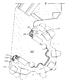
journal pin 10A. In various axial seal embodiments, the axial surfaces 20C,
20D include thereon a material similar or identical in nature to the materials
described for the foregoing radial seal embodiments, this material being
adapted to withstand moving contact between the cone and journal pin and the
mating seal surfaces. Lateral surfaces 20E, 20F in axial seals may be formed
having a depression or recess therein when the seal 20A is axially
uncompressed, such that when the seal is axially compressed, the lateral
surfaces 20E, 20F are substantially planar, and/or provide clearance between
the lateral surfaces 20E, 20F and the walls of the groove 22A. This is
substantially the same concept as for the radial seal shown in Figures 3 and
4.
[0056] All of the foregoing description relating to radial seals is likewise
applicable to axial seals with respect to the dynamic sealing surfaces, the
contact stress profiles and selected materials. The difference between axial
and
radial seal embodiments is merely that the orientation of all the elements of
an
axial seal, according to the various embodiments of the invention, are rotated
about 90 degrees with respect to the seal dimensions as compared to the radial
seal embodiments described herein previously.
[0057] It should also be noted that the invention is not limited only to axial
or
radial seals, wherein the sealing surfaces are on opposite sides of the seal
body.
Other types of seals, referred to as "canted seals", include sealing surfaces
on
18
'CA 02396692 2002-08-02
the roller cone and on the journal pin which are opposed to each other across
the seal body along a line which is neither parallel to the bearing axis (as
is the
case for axial seals) nor perpendicular to the bearing axis (as is the case
for
lateral seals). In various embodiments of canted seals, first and second
dynamic sealing surfaces on the seal may include a material adapted to
withstand relative rotation between the roller cone and the journal pin, as in
the
other embodiments of the invention. The only difference is that in canted
seals,
the dynamic sealing surfaces on opposite sides of the seal body are compressed
along a line which includes both axial and radial components. Other aspects of
the various embodiments of the invention, including the various shapes of the
boundary between the seal body and the dynamic sealing surface materials to
provide a selected contact stress profile, and the various external sealing
surface shapes of the dynamic sealing surfaces, are equally applicable to
various embodiments of a canted seal according to the invention.
[0058] An example of a canted seal is shown in Figure 8. The canted seal 80 is
shown disposed in a seal groove 81 in the roller cone 83. As in other
embodiments, the seal groove may alternatively be disposed in the bit body in
the journal area. The seal 80 includes first 84 and second 86 dynamic sealing
surfaces which are compressed along a line 82 which is neither parallel to the
bearing axis 88 nor perpendicular to the bearing axis 88. Thus, compression of
the canted seal 80 includes both axial and radial components.
[0059] While the invention has been described with respect to a limited number
of embodiments, those skilled in the art, having benefit of this disclosure,
will
appreciate that other embodiments can be devised which do not depart from the
scope of the invention as disclosed herein. Accordingly, the scope of the
invention should be limited only by the attached claims.
19