Note : Les descriptions sont présentées dans la langue officielle dans laquelle elles ont été soumises.
CA 02397350 2009-01-12
MULTIPLE LUMEN HEAT EXCHANGE CATHETERS
FIELD OF THE INVENTION
.10 This invention relates generally to medical devices and a method of using
them for selectively affecting the temperature of a patient's body, or portion
of the
patient's body, by adding or removing heat from the patient's body fluid
through the
use of a heat exchange catheter with a heat exchange region in contact with
the
body fluid, the heat exchange region being shaped for maximum heat exchange
with
minimum insertion profile and minimum obstruction to the flow of the body
fluid.
More particularly, this invention relates to a heat exchange catheter with a
heat
exchange region which is an advantageously shaped balloon, wherein the balloon
is placed in flowing body fluid and heat exchange fluid circulates within the
balloon
to add or remove heat from the body fluid in order to treat or induce whole
body or
regional hypothermia or hyperthermia. This invention also relates to a method
of
controlling the amount of heat removed or added by the heat exchange region to
affect the temperature of all or part of the patient's body in response to a
signal
representing the temperature of all or part of a patient's body.
1
CA 02397350 2002-07-26
WO 01/58397 PCT/US01/03828
BACKGROUND OF THE INVENTION
Under ordinary circumstances, thermoregulatory mechanisms exist in the
healthy human body to maintain the body at a constant temperature of about 370
C(98.6 F), a condition sometimes referred to as normothermia. Normothermia is
generally a desirable condition, and to maintain normothermia, the
thermoregulatory
mechanisms act so that heat lost to the environment is replaced by the same
amount of heat generated by metabolic activity in the body.
Forvarious reasons, a person may develop a body temperature that is below
normothermia, a condition known as hypothermia, or a temperature that is above
normothermia, a condition known as hyperthermia. These conditions are
generally
harmful and are usually treated to reverse the condition and return the
patient to
normothermia. In certain other situations, however, they may be desirable and
may
even be intentionally induced.
Accidental hypothermia may result when heat loss to the environment
exceeds the body's ability to produce heat internally or when a person's
thermoregulatory ability has been lessened due to injury, illness or
anesthesia. For
example, a person exposed to a cold environment such as a hiker wandering in a
very cold climate for too long, or a sailor overboard in cold water, may
become
dangerously hypothermic. Likewise, anesthesia generally disables a patient's
thermoregulatory ability, and it is often the case that, during long surgery
with
significant exposure of the patient's internal body cavities, a patient
becomes
significantly hypothermic. Such hypothermia is generally harmful, and must be
quickly reversed to restore the victim to health.
Simple methods for treating hypothermia have been known since very early
times. Such methods include wrapping the patient in blankets, administering
warm
fluids by mouth, and immersing the patient in a warm water bath. If the
hypothermia
is not too severe, and the need to reverse the hypothermia is not to urgent,
these
methods may be effective. However, wrapping a patient in a blanket depends on
the ability of the patient's own body to generate heat to re-warm the body.
Administering warm fluids by mouth relies on the patient's ability to swallow,
and is
limited both in the temperature of the liquid consumed and the amount of fluid
that
2
CA 02397350 2002-07-26
WO 01/58397 PCT/US01/03828
may be administered in a limited period of time. Immersing a patient in warm
water
is often impractical, particularly if the patient is simultaneously undergoing
surgery
or some other medical procedure
More recently, hypothermia may be treated by the application of a warming
blanket that applies heat to the skin of the patient. Applying heat to the
patient's
skin, however, may be ineffective in providing heat to the core of the
patient's body.
Heat applied to the skin has to transmit through the skin by conduction or
radiation
which may be slow and inefficient, especially if the patient has a significant
layer of
fat between the warming blanket and the body's core.
Paradoxically, if the patient is suffering significant core hypothermia, the
application of warmth to the patient's skin, whether by immersion in hot water
or
application of a warm blanket, may actually exacerbate the core hypothermia
and
may even induce shock. The body's thermoregulatory responses to cold that work
to conserve heat in the body's core include vasoconstriction and arterio-
venous
shunting (AV shunts). Vasoconstriction occurs when the capillaries and other
blood
vessels in the skin and extremities constrict so that most of the blood pumped
by the
heart circulates within the core rather than through the skin and extremities.
Similarly, in AV shunting, naturally occurring blood shunts exist between some
arteries providing blood to capillary beds in the skin and extremities and
veins
returning blood from those capillary beds and extremities. When the body is
cooled,
the vessels in the capillary beds constrict, and the shunts may be opened,
causing
blood to by-pass those capillary beds altogether. Thus when the body is cold,
the
tissues in the extremities, and particularly at the surface, have little blood
flowing to
them and may become quite cold relative to the body's core temperature.
When heat is applied to the skin of such a patient, the temperature sensors
in the skin may cause the vasoconstriction to reverse and the AV shunts to
close.
When this happens, blood from the core floods into the very cold tissue on the
body
surface and extremities, and as a result the blood loses heat to those
tissues, often
far more than the amount of heat being added by the surface warming. As a
result,
the victim's core temperature may plummet and the patient may even go into
shock.
3
CA 02397350 2002-07-26
WO 01/58397 PCT/US01/03828
Partly in response to the inadequacies of surface application of heat,
methods have been developed for adding heat to a patient's body by internal
means. A patient being administered breathing gases, for example a patient
under
anesthesia, may have the breathing gases warmed. For some situations,
particularly mild hypothermia requiring the addition of small amounts of heat,
this
method may be effective, but it is limited in the amount of heat that can be
administered without injuring the lungs. Similarly, a patient receiving IV
fluids may
have the fluids warmed, or a bolus of warm fluid may be administered
intravenously.
Again, this may be effective in the case of mild hypothermia, but the amount
of heat
that may be added to a patient's body is limited because the temperature of
the IV
fluid is limited to a temperature that will not be destructive to the blood,
generally
thought to be about 41 C - 49 C, and the amount of fluid that is acceptable
to
administer to the patient.
A more invasive method may be used to add heat to a patient's blood,
particularly in the case of heart surgery. A cannula is attached to a vein,
usually the
inferior vena cava (IVC) of a patient, the vein clamped off and virtually all
the
patient's blood shunted through the cannula to an external pump. The blood is
then
pumped back into the patient's body, generally to the arterial side of the
patient's
circulation. Blood removed from a patient may be heated or cooled externally
before it is reintroduced into the patient's body. An example of such a by-
pass
arrangement is the Cardio-Pulmonary By-pass system (CPB) often used in open
heart surgery.
This by-pass method, once it is initiated, is both fast and effective in
adding
or removing heat from a patient's blood and in exercising control over the
patient's
body temperature in general, but has the disadvantage of involving a very
invasive
medical procedure which requires the use of complex equipment, a team of
highly
skilled operators, is generally only available in a surgical setting, and
because of
these complexities, requires a long time to initiate. In fact, it generally
cannot begin
until after the patient's thorax has been surgically opened. For all these
reasons,
it is generally not useful for emergency treatment of hypothermia. By-pass
also
involves mechanical pumping of blood, which is generally very destructive to
the
4
CA 02397350 2009-01-12
blood resulting in cytotoxic and thrombolytic problems associated with removal
of
blood from the body, channeling the blood through various tubes, artificially
oxygenating the blood, and returning the blood subjected to these stresses to
the
circulatory system, including the brain. Because of the potential harmful
impact on
the patient, most surgeons attempt to limit the time a patient is subjected to
by-pass
to less than four hours.
Methods for adding heat to the core of the body that do not involve pumping
the blood with an external, mechanical pump have been suggested. For example,
a method of treating or inducing hypothermia or hyperthermia by means of a
heat
exchange catheter placed in the bloodstream of a patient was described in U.S.
Patent No. 5,486,208 to Ginsburg.
That patent discloses and claims a method of increasing a
patient's body temperature by adding heat to the blood by inserting a heat
exchange
catheter having a balloon with heat exchange fins into the vascular system and
circulating heat exchange fluid through the balloon while the balloon is in
contact
with the blood.
Although accidental hypothermia is generally harmful and requires treatment,
in some instances it may be desirable to induce hypothermia or permit it to
persist
in a controlled situation. Hypothermia is generally recognized as being
neuroprotective and may be induced for that reason. Neural tissue such as the
brain or spinal cord, is particularly subject to damage by vascular disease
processes
including, but not limited to ischemic or hemorrhagic stroke, blood
deprivation for
any reason including cardiac arrest, intracerebral or intracranial hemorrhage,
and
head trauma. Other where hypothermia may be protective include treatment of
myocardial infarction, and heart surgery, neurosurgical procedures such as
aneurysm repair, endovascular aneurysm repair procedures, spinal surgeries,
procedures where the patient is at risk for brain, cardiac or spinal ischemia
such as
beating heart by-pass surgery or any surgery where the blood supply to the
heart,
brain or spinal cord may be temporarily interrupted. In each of these
instances,
damage to brain tissue may occur because of brain ischemia, increased
intracranial
pressure, edema or other processes, often resulting in a loss of cerebral
function
5
CA 02397350 2002-07-26
WO 01/58397 PCT/US01/03828
and permanent neurological deficits. Hypothermia may be intentionally induced
because it is advantageous in such situations. In fact, in some of these
situations,
such as beating heart by-pass surgery, hypothermia currently occurs as a
normal
side effect of anesthesia disabling a patient's normal thermoregulatory
responses
in conjunction with prolonged exposure of the chest cavity. The resultant
hypothermia may not itself be harmful if adequate control over the patient's
temperature is established, and where the hypothermic condition is controlled
as to
depth and duration, it may be permitted to persist or even induced. Control of
the
depth of hypothermia and reversal of hypothermia after the operation are both
important, and if that control is not possible, hypothermia is generally
thought to be
undesireable.
Although the exact mechanism for neuroprotection is not fully understood,
lowering the brain temperature is believed to effect neuroprotection through
several mechanisms including, the blunting of any elevation in the
concentration
of neurotransmitters (e.g., glutamate) occurring after ischemic insult,
reduction of
cerebral metabolic rate, moderation of intracellular calcium
transport/metabolism,
prevention of ischemia-induced inhibitions of intracellular protein synthesis
and/or
reduction of free radical formation as well as other enzymatic cascades and
even
genetic responses.
Besides its benefrt as a prophylactic measure, forexample during surgery
to prevent damage in case of neurologic ischemia, it is also sometimes
desirable
to induce whole-body or regional hypothermia for as a treatment in response to
certain neurological diseases or disorders such as head trauma, spinal trauma
and hemorrhagic or ischemic stroke. Hypothermia has also been found to be
advantageous as a treatment to protect both neural tissue and cardiac muscle
tissue after a myocardial infract (M1). Again, the exact mechanism of benefit
is
not known, but inducing hypothermia in such situations, after the initial
ischemic
insult, may lessen damage by decreasing reperfusion injury, interrupting
various
chemical cascades that would otherwise damage the cells involved, protecting
membrane integrity and perhaps even preventing certain genetic changes
leading to apoptosis.
6
CA 02397350 2002-07-26
WO 01/58397 PCT/US01/03828
Intentionally inducing hypothermia has generally been attempted by either
surface cooling or by-pass pumping. Surface cooling has generally proved to be
unacceptably slow, since the body heat to be removed must be transmitted from
the core to the surface, and has sometimes been altogether unsuccessful since
the body's thermoregulatory mechanisms act to oppose any attempt to induce
hypothermia and generally succeed in preventing surface cooling from reducing
the core temperature of the body. For example, the vasoconstriction and AV
shunting may prevent heat generated in the core from being transmitted to the
surface by the blood. Thus the surface cooling may only succeed in removing
heat from the skin and surface tissue and thus cooling the surface, and not
succeed in reducing the core temperature of the patient.
Another thermoregulatory mechanism that may thwart attempts to reduce
core temperature by surface cooling is shivering. There are numerous
temperature sensors on the body's surface, and these may trigger the body to
begin shivering. Shivering results in the generation of a significant amount
of
metabolic heat, as much as five times more than the resting body, and
especially
where vasoconstriction and AV shunting reduce blood to the surface of the
body,
suface cooling such as by a cooling blanket can only reduce the temperature of
the patient very slowly, if at all. Even if the thermoregulatory mechanisms
are
disabled by anesthesia or other drugs, it has generally been found that the
cooling by surface measures such as blankets is unacceptably slow for inducing
hypothermia. If the patient has fever and thus an elevated set point
temperature
(the temperature which the body's thermoregulatory responses act to maintain),
the patient may even shiver at a temperature above normothermia. In such
situations, it has been found that surface cooling is often unable to reduce
the
patient's temperature even to normothermia. Furthermore, besides often being
ineffective and generally being unacceptably slow, surface cooling lacks
sufficient control over the target temperature of the patient, since the
methods
are inadequate to quickly adjust the patient's body temperature and therefore
may result in overshoot or other uncontrolled body temperature problems that
cannot be adequately managed .
7
CA 02397350 2002-07-26
WO 01/58397 PCT/US01/03828
Inducing hypothermia using by-pass techniques is generally effective, fast
and controllable, but is also subject to the shortcomings of the by-pass
method
for adding heat to control accidental hypothermia; it requires a very invasive
procedure in an operating room under full anesthesia, with intubation,
expensive
equipment and highly trained personnel. Even in the situation of open heart
surgery or neurosurgery where the patient is in the operating suite and has
highly skilled personnel in attendance anyway, the by-pass mechanism requires
pumping the blood with a mechanical pump through external circuit, which is
generally thought to be very destructive of the blood and is generally not
maintained for very long, preferably four hours or less, and cooling cannot be
begun before the patient's thorax is opened and a shunt surgically installed,
itself
a procedure that might induce some neurological ischemia, or continued, nor
warming effected, after the patient's thorax is closed. Thus any advantage of
pre-cooling before the patient is opened, or continued after or re-warmed
after
the patient is closed, is not attained by this method, and the patient is
exposed
to the undesirable effects of external pumping.
Cold breathing gases and cold infusions have generally not been used to
induce hypothermia. Breathing cold gases is generally ineffective to induce
hypothermia since the lungs are generally structured to be able to breathe
very
cold air without rapidly inducing hypothermia. Injection of cold infusate
would
generally be unacceptable as a method of inducing and maintaining hypothermia
because infusing the large volume of liquid that would be necessary to induce
and maintain hypothermia for a useful length of time would be unacceptable.
The previously mentioned heat exchanged cathetger placed in the
bloodstream of a patient overcomes many of these inadequacies of the other
methods of combating accidental hypothermia, or intentionally inducing
hypothermia. Particularly in view of the body's own thermoregulatory attempts
to maintain normothermia, a very efficient heat exchange catheter is highly
desirable.
Under certain conditions heat is generated within the body or heat is
added from the environment in excess of the body's ability to dissipate heat,
and
8
CA 02397350 2002-07-26
WO 01/58397 PCT/US01/03828
a persons develops a condition of abnormally high body temperature, a
condition
known as hyperthermia. Examples of this condition may result from exposure to
a hot and humid environment or surroundings, overexertion, or exposure to the
sun while the body's thermoregulatory mechanisms are disabled by drugs or
disease. Additionally, often as a result of injury or disease, a person may
establish a set point temperature that is above the normal body temperature of
about 37 C. a condition generally known as fever. In another condition,
malignant hyperthermia, a condition not well understood, the body may fail to
dissipate enough heat and the temperature of the body may spiral to dangerous
levels without the body's normal mechanisms being effective to return the
patient
to normothermia.
Prolonged and severe hyperthermia may have serious and very negative
effects. For example, a child with prolonged and high fever as a result of
spinal
meningitis might suffer permanent brain damage. In stroke, the presence of
even
a mild fever has been found to correlate with very negative outcome. In such
cases, it may be very desirable to counteract the body's attempt to establish
a
higher temperature, and instead to maintain at temperature at or near
normothermia. However, the unaided body is acting to maintain a temperature
above 37 C. and the body's own thermoregulatory mechanisms, such as AV
shunting and shivering may render surface cooling altogether ineffective in
reestablishing normothermia. The advantages of an effective core cooling
method are sorely needed in such situations.
As with hypothermia, counter-parts to simple methods for treating
undesirable hyperthermia exist, such as cold water baths and cooling blankets,
as well as more effective but complex and invasive means such as cooled
breathing gases and blood cooled during by-pass. These, however, are subject
to the limitations and complications as described above in connection with
hypothermia. In addition, as is the case when attempting to induce
hypothermia,
the thermoregulatory responses of the body such as vasoconstriction, AV
shunting and shivering, may act directly to combat the attempt to cool the
patient
and thereby defeat the effort to treat the hyperthermia. In order to achieve
the
9
CA 02397350 2002-07-26
WO 01/58397 PCT/US01/03828
reduction of accidental, diseased or malignant hyperthermia, a catheter with
sufficient heat exchange effectiveness to override the body's thermoregulatory
defenses is needed.
For various reasons, it may be desirable to induce and/or maintain
hyperthermia. For example, certain cancerceNs may be sensitive to temperature
elevations, and thus it may be possible to destroy those cancerous cells by
elevating a patient's temperature to a(evef that is toxic to the cancer cells
but the
rest of the body can tolerate. As another example, a high temperature may be
toxic to certain viruses at a level that the rest of the body can tolerate.
Raising
the patient's temperature above that which the virus can tolerate but within a
temperature range the body can tolerate would help to rid the body of the
virus.
A heat exchanger that can add heat to the bloodstream of a patient at a
sufficient rate to maintain the patient in a state of hyperthermia would
therefore
be desirable.
Besides intentionally induced hypothermia or hyperthermia, it is
sometimes desirable to control a patient's temperature to maintain a target
temperature, sometimes but not always normothermia. For example, in a patient
under general anesthesia during major surgery, the anesthesiologist may wish
to control the patient's body temperature by directly adding or removing heat.
In such a situation, the patient's normal thermoregulatory responses are
reduced
or eliminated by anesthesia, and the patient may lose an extraordinary amount
of heat to the environment. The patient's unaided body may not generate
sufficient heat to compensate forthe heat lost and the patient's temperature
may
drift lower. The anesthesiologist may wish to control the temperature at
normothermia, or may prefer to allow the patient to become somewhat
hypothermic, but control the depth and duration of the hypothermia. A device
and method for precisely controlling body temperature by efficiently adding or
removing heat to control a patient's temperature would be very desirable.
In addition to controlling the patient's body temperature, fast and precise
control of the adjustments to a patient's thermal condition is very important
when
a patient's temperature is being manipulated. When using heat transferfrom the
CA 02397350 2002-07-26
WO 01/58397 PCT/US01/03828
surface to the core of a patient as by the application of warming or cooling
blankets, besides being slow and inefficient, the control of the patient's
core
temperature is very difficult, if not impossible. The temperature of the
patient
tends to "overshoot" the desired low temperature, a potentially catastrophic
problem when reducing the core temperature of a patient, especially to
moderate
or sever levels. The body's own metabolic activity and thermoregulatory
responses may make even gross adjustments of core temperature by surface
cooling difficult, slow, or even impossible. Speedy and precise control is
generally not possible by such methods at all.
Control of body temperature using by-pass techniques is generally fairly
precise and relatively fast, especially if large volumes of blood are being
pumped
through the system very quickly. However, as was previously stated, this
method is complex, expensive, invasive and it is this very pumping of large
quantities of blood that may be seriously damaging to the patient,
particularly if
maintained for any significant period of time, for example for or more hours.
An efficient heat exchanger might make possible the manipulation of
temperature of a select portion of a patient's body. Generally, the
temperature
throughout the body is relatively constant and generally does not vary
significantly from one location to another. (One exception is the skin, which
because of exposure to the environment may vary significantly in temperature.
In fact, many of the thermoregulatory mechanisms discussed above depend on
the ability of the skin to maintain a different temperature, generally a lower
temperature, than the temperature of the core of the body.) The mammalian
body generally functions most efficiently at normothermia. In some instances,
however, regional hypothermia or hyperthermia (hypothermia or hyperthermia
of only a part of the body while the rest of the body is at a different
temperature,
preferably normothermia) may be advantageous. For example, it could be
advantageous to cool the head for purposes of neuroprotection of the brain or
cool the heart to protect the myocardium from suffering infarction during or
after
ischemia, or heating a cancerous region to destroy cancerous cells, while
maintaining the rest of the body at normal, healthy temperature so that the
11
CA 02397350 2002-07-26
WO 01/58397 PCT/US01/03828
disadvantages of whole body hypothermia or hyperthermia would not occur.
Additionally, where the entire body is cooled, shivering and other
thermoregulatory mechanisms may act to counter attempts to cool the body, and
if only a specific region were targeted for cooling, those mechanisms might be
obviated or eliminated.
A heat exchanger in contact with body fluid, such as blood, which was
directed to the target area, might alter the temperature of that region if the
heat
exchanger was efficient enough to cool the blood sufficiently to cool the
tissue
in question even if the body temperature, i.e. the initial temperature of the
blood
flowing past the heat exchange region was normothermic. A heat exchange
catheter with a highly efficient heat exchange region would be required for
such
an application. Where the catheter is inserted percutaneously into the
vasculature, it is also highly desirable to have as small an insertion profile
as
possible to allow as small a puncture as possible, yet allow maximum surface
area of the heat exchange region in contact with the flowing blood. Such a
catheter is the subject of this application.
For all the foregoing reasons, there is a need for a means to add or
remove heat from the body of a patient in an effective and efficient manner,
while
avoiding the inadequacies of surface heat exchange and avoiding the dangers
of internal methods including by-pass methods. There is the need for a means
of rapidly, efficiently and controllably exchanging heat with the blood of a
patient
so the temperature of the patient ortarget tissue within the patient can be
altered
or controllably maintained at some target temperature.
Positioning a catheter centrally within the flowing bloodstream may be
important for various reasons. Contact between a hot or cold heat exchange
region and the walls of a body conduit such as a blood vessel may affect the
tissue at the point of contact. In some applications, such as where the user
seeks to tack the surface of a dissected vessel to the wall of the vessel, or
to
thermally treat or ablate the tissue in question, the contact between the
balloon
and the surrounding body structure is important, even critical. Where,
however,
12
CA 02397350 2002-07-26
WO 01/58397 PCT/US01/03828
the contact is undesirable, it would be advantageous to have a means to
prevent
the heat exchange region from resting against the vessel wall.
Where temperature control of the temperature of the blood is the goal, it
is also advantageous to position the heat exchange region in the center of a
flow
of body fluid, for example in the center of the lumen of a blood vessel so
that the
blood flow would surround the entire balloon and no portion of the balloon
surface would be sheltered from the flow and thus prevented from exchanging
heat at the balloon surface with the body fluid. This would also help prevent
blood to pool in areas of low flow or lack of flow, which has been shown to
cause
blood to clot.
It would be particularly advantageous if the heat exchange surface could
be configured to maximize the surface area in contact with the blood while
minimizing the obstruction to fluid flow within the vessel. This is desirable
both
because maximum flow is important for maximum heat exchange and because
maximum flow will assure that there is adequate blood supply to tissue
downstream of the heat exchange region. Thus the rate of the blood flow past
the heat exchange region should be maximized at the same time that the surface
area of the heat exchange region within the stream of flowing blood is
maximized. A catheter that could achieve these seemingly contradictory goals
would be highly desirable.
Additionally, where heat exchange is occurring between two flowing fluids,
it is most efficient to have counter-current flow. That is, the flow of the
heat
exchange liquid is counter to the flow direction of the fluid with which it is
exchanging heat. Since a heat exchange catheter might be inserted into blood
vessels in various ways that would result in the natural blood flowing being
different in different instances (i.e. proximal to distal, or distal to
proximal) it
would advantageous to have a catheter wherein the direction of the fluid flow
in
the portion of the balloon exposed to the flow of the body fluid could be
adjusted
to flow in either direction to permit the catheter could be inserted into the
blood
vessel in either direction, and the direction of the flow of the heat exchange
fluid
adjusted to flow counter to the flow in the vessel.
13
CA 02397350 2002-07-26
WO 01/58397 PCT/US01/03828
If the heat exchange catheter is to be inserted into the vasculature of a
patient, it is very advantageous to have a small insertion profile, that is to
say a
diameter of the device at insertion that is a small as possible. This permits
the
insertion of the device through as small sheath, puncture, or incision. Yet
the
surface area of the heat exchange region should be maximized when the
catheter is functioning to exchange heat with the blood. Once again, these
goals
seem contradictory, and a heat exchange catheter that could achieve both
characteristics would be highly advantageous.
14
CA 02397350 2002-07-26
WO 01/58397 PCT/US01/03828
SUMMARY OF THE INVENTION
The present invention provides a heat exchange catheter having a heat
exchange region that comprises a balloon having multiple lumens for
circulation
of a heat exchange medium and a method for accomplishing intravascular heat
exchange by circulation of heat exchange medium from outside the body through
a multi-lumen shaft and through a multi-lumen balloon having curvilinear
(e.g.,
helical, twisted or other curved configuration) balloon elements such as
balloon
lobes in contact with a patient's blood.
Further in accordance with the invention, there is provided a heat
exchange catheter having a heat exchange region that comprises at least one
balloon having multiple lumens for circulation of a heat exchange medium and
a method for accomplishing intravascular heat exchange by circulation of heat
exchange medium from outside the body through a multi-lumen shaft and
through a shaped multi-lumen balloon in contact with a patient's blood. The
method further may include altering the temperature of the heat exchange fluid
outside the body so that it is a temperature different than the temperature of
the
patient's blood, placing the heat exchange region in contact with the
patient's
blood, and circulating the heat exchange fluid through the heat exchange
region
to exchange heat with the bloodstream at a sufficient rate and for a
sufficient
length of time to effect regional or whole body temperature modification of
the
patient.
Further in accordance with the invention, a heat exchange catheter of the
invention may comprise a flexible catheter body or shaft having a proximal end
and a distal end, the distal end of such catheter shaft being adapted to be
inserted percutaneously into the vasculature or body cavity of a mammalian
patient. A heat exchange region is provided on the catheter shaft, comprising
a balloon with a plurality of lumens helically wound around a central axis. (A
balloon is defined as a structure that is readily expandable under pressure
and
collapsible under vacuum and includes both elastomeric structures and non-
elastomeric structures that are deformable in the manner described.) The shaft
of the catheter preferably includes a fluid circulation path or lumen, and
each
CA 02397350 2002-07-26
WO 01/58397 PCT/US01/03828
heat exchange element preferably is attached at both ends of the shaft and
incorporates a fluid circulation path or lumen that is in fluid communication
with
the fluid circulation path or lumen of the catheter shaft. In this manner,
heat,
exchange fluid may be circulated into or through the heat exchange region as
it
is circumferentially surrounded by the body fluid.
Further in accordance with some embodiments of the invention, the heat
exchange region may be less than the length of the portion of the catheter
inserted into the patient and may be located at or near the distal end
thereof. In
such embodiments, an insulating region may be formed on the catheter shaft
proximal to the heat exchange region to reduce unwanted transfer of heat to
and
from the proximal portion of the catheter shaft.
Further in accordance with the present invention, there is provided a
system for heat exchange with a body fluid, the system including a) a liquid
heat
exchange medium and b) a heat exchange catheter having a heat exchange
region comprising a balloon having helicaly formed lumens. The catheter
includes a shaft having a proximal end and a distal end, the distal end
adapted
to be inserted percutaneously into a body cavity. The shaft having a
circulation
pathway therein for the circulation of heat exchange medium therethrough. The
heat exchange region is attached to the catheter so that when the catheter is
inserted in the body cavity, body fluid surrounds the heat exchange region.
Further in accordance with the present invention, the heat exchange
region is deflated for percutaneous insertion into the patient's vasculature
to a
small diameter, and once positioned with the heat exchanger in the
vasculature,
the heat exhange region may be inflated to a larger diameter to increase the
surface area of the heat exchange region for maximum heat exchange with the
blood.
The system further may include a sensor or sensors attached to the
patient to provide feedback on the condition of the patient, for example the
patient's temperature. The sensors are desirably in communication with a
controller that controls the heat exchange catheter based on the feedback from
the sensors.
16
CA 02397350 2002-07-26
WO 01/58397 PCT/US01/03828
Still further in accordance with the present invention, there is provided a
method for exchanging heat with a body fluid of a mammal. The method
includes the steps of a) providing a catheter that has a circulatory fluid
flow path
therein and a heat exchange region thereon, such heat exchange region
including heat exchange elements that are attached to the catheter shaft at
the
heat exchange region, b) inserting the catheter into a body cavity and into
contact with a body fluid, the heat exchange elements thus being surrounded by
the body fluid and c) causing a heat exchange medium to flow through the
circulatory flow path of the catheter so that the medium exchanges heat with a
body fluid through the heat exchange elements. Each of the heat exchange
elements may be hollow balloon lobes, and step C of the method may include
causing heat exchange fluid to flow through the hollow heat exchange elements.
It is an object of this invention to provide an effective and advantageous
heat exchange region for adding heat to a patient suffering from hypothermia.
It is a further object of this invention to provide an effective means for
removing heat from the bloodstream of a patient suffering from hyperthermia.
It is a further object of this invention to provide an effective means of
adding or removing heat from a patient to induce normothermia.
It is a further object of this invention to provide an effective means for
maintaining normothermia.
It is a further object of this invention to provide an effective means of
cooling a patient to a target temperature and controllably maintaining that
temperature.
It is a further object of this invention to provide a heat exchange catheter
that has an advantageous configuration that provides for maximum heat
exchange with blood flowing in heat exchange proximity to the heat exchange
region.
It is a further object of this invention to provide a heat exchange catheter
that has an advantageous shape that attains an advantageous ratio of heat
exchange surface area while maintaining adequate flow in a blood vessel.
17
CA 02397350 2002-07-26
WO 01/58397 PCT/US01/03828
It is a further object of this invention to provide a catheter with a
sufficiently effective and efficient heat exchange region to cool a target
region of
a patient.
It is a further object of this invention to provide a catheter with a
sufficiently effective and efficient heat exchange region to precisely
maintain a
patient at a target temperature.
It is a further object of this invention to provide a heat exchange catheter
that is configured to efficiently exchange heat with the blood of a patient
while
allowing continued flow of the blood past the catheter with a minimum of
restriction to that blood flow.
It is a further object of this invention to provide a heat exchange catheter
having a heat exchange region comprised of multiple balloon elements such as
lobes.
It is a further object of this invention to provide a heat exchange catheter
having an insulated shaft.
It is a further object of this invention to provide an effective method of
controlling the temperature of a body fluid.
It is a further object of this invention to provide an effective method of
warming a body fluid.
It is a further object of this invention to provide an effective method of
cooling a body fluid.
It is a further object of this invention to provide an effective method for
inducing hypothermia.
It is a further object of this invention to provide a catheter having a heat
exchange region wherein the temperature is controlled by the temperature of
flowing heat exchange fluid and wherein the direction of the fluid flow may be
reversed.
It is a further object of this invention to provide a heat exchange catheter
having a heat exchange region wherein, when the heat exchange region is
placed within a blood vessel, the shape of the heat exchange region assists in
centering the heat exchange region within the vessel.
18
CA 02397350 2002-07-26
WO 01/58397 PCT/US01/03828
It is a further object of this invention to provide a heat exchange catheter
having a heat exchange region composed of multiple, non-coaxial balloon
elements such as lobes of a multi-lobed balloon.
These and other objects of this invention will be understood with
reference to the following drawings and description.
BRIEF DESCRIPTION OF THE DRAWINGS
FIGURE 1 is a perspective drawing of an embodiment of the catheter of
the invention.
FIGURE 1A is a perspective drawing of an alternative tie-down at the
proximal end of the catheter shown in FIGURE 1.
FIGURE 2 is a cross-sectional drawing of the shaft of the catheter taken
along the line 2-2 in FIGURE 1.
FIGURE 3 is a cross-sectional drawing of the heat exchange region of the
catheter taken along the line 3-3 in FIGURE 1.
FIGURE 3A is a cross-sectional drawing of the heat exchange region of
the catheter taken along the line 3A - 3A in FIGURE 1.
FIGURE 4 is a perspective drawing of a segment of the heat exchange
region of the catheter within the circle 4-4 in FIGURE 1.
FIGURE 5 is a cross-sectional drawing of the heat exchange region of the
catheter taken along the line 5-5 in FIGURE 1.
FIGURE 6 is a perspective drawing of a segment of the heat exchange
region of the catheter within the circle 6-6 in FIGURE 1.
FIGURE 7 is a perspective drawing of the multi-lobed balloon of one
embodiment of the invention.
FIGURE 8 is a perspective drawing of the distal portion of the shaft of one
embodiment of the invention.
FIGURE 9 is a perspective drawing, partially in ghost, of the heat
exchange region formed by the shaft and multi-lobed balloon of FIGURES 7 and
8.
19
CA 02397350 2002-07-26
WO 01/58397 PCT/US01/03828
FIGURE 10 is an expanded view of the attachment of the central lumen
of the balloon to the shaft of the catheter of FIGURE 9 showing the region
within
the circle 10-10 in FIGURE 9.
FIGURE 10 A is an expanded view of the plug between the shaft and the
central lumen of the balloon of the catheter of FIGURE 9 showing the region
within the circle 10A-10A in FIGURE 9.
FIGURE 11 is a perspective view of a portion of a multi-lobed curvilinear
heat exchange balloon of one embodiment of the invention.
FIGURE 11 A is a cross sectional view of the heat exchange region taken
along the line 11A-11A in FIGURE 11.
FIGURE 12 is a sectional view of the proximal portion of the heat
exchange region of one embodiment of the invention.
FIGURE 12A is a cross-sectional view of a portion of the heat exchange
region taken along the line 12A-12A of FIGURE 12.
FIGURE 12B is a cross-sectional view of a portion of the heat exchange
region taken along the line 12B-12B of FIGURE 12.
FIGURE 12C is a cross-sectional view of a portion of the heat exchange
region taken along the line 12C-12C of FIGURE 12.
FIGURE 13 is a sectional view of the distal portion of the heat exchange
region of one embodiment of the invention.
FIGURE 13A is a cross-sectional view of a portion of the heat exchange
region taken along the line 13A-13A of FIGURE 13.
FIGURE 13B is a cross-sectional view of a portion of the heat exchange
region taken along the line 13B-13B of FIGURE 13.
FIGURE 14 is a sectional view of the distal portion of the heat exchange
region of one embodiment of the invention.
FIGURE 15A is a side view, partially in ghost, of the heat exchange region
of one embodiment of the invention.
FIGURE 15B is a cross-section taken along the line 15B-15B in FIGURE
15A.
CA 02397350 2002-07-26
WO 01/58397 PCT/US01/03828
FIGURE 15C is a cross-section taken along the line 15C-15C in FIGURE
15A.
FIGURE 15D is a cross-section taken along the line 15D-15D in FIGURE
15A.
FIGURE 15E is a cross-section taken along the line 15E-15E in FIGURE
15A.
FIGURE 15F is a cross-section taken along the line 15F-15F in FIGURE
15A.
FIGURE 16A is a perspective view of one embodiment of an intavascular
heat exchange catheter according to the present invention.
FIGURE 16B is a front perspective view of one embodiment of an
extracorporeal temperature control console that is useable in conjunction with
the catheter of Figure 16A to accomplish temperature management of a human
or veterinary patient.
FIGURE 17 is a flowchart of an exemplary method of the invention.
DETAILED DESCRIPTION
The present invention provides an improved heat exchange catheter that
provides an efficient and effective heat exchange region to exchange heat with
body fluid while maintaining a minimum insertion profile of the catheter. The
heat exchange catheter generally comprises a catheter having a shaft for the
flow of heat exchange fluid to and from a heat exchange region, and the heat
exchange region comprising an advantageously configured multiple lumen
balloon wherein the heat exchange fluid flows through the balloon and blood
flows over the outside of the balloon and heat is exchanged through the walls
of
the balloon between the heat exchange fluid flowing inside the balloon and the
blood flowing outside the balloon.
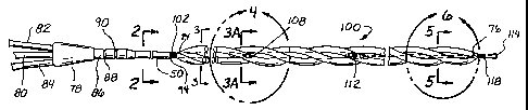
Referring to Figures 1 through 10A, in one advantageous embodiment,
the catheter is comprised of a shaft 50 with a heat exchange region 100
thereon.
The shaft has two roughly parallel lumens running through the proximal shaft,
an
inflow lumen 52 and an outflow lumen 54. The shaft generally also comprises
21
CA 02397350 2002-07-26
WO 01/58397 PCT/US01/03828
a working lumen 56 running therethrough for the insertion of a guide wire, or
the
application of drugs, radiographic dye, or the like to the distal end of the
catheter.
The heat exchange region comprises a four-lumen balloon, with three outer
lumens 58, 60, 62 disposed around an inner lumen 64 in a helical pattern. In
the
particular embodiment shown, the balloon preferable makes one full rotation
about the inner lumen 64 for each 2 to 4 inches of length. All four lumens are
thin
walled balloons and each outer lumen shares a common thin wall segment 66,
68, 70 with the inner lumen. The balloon is approximately twenty-five
centimeters long, and when inflated has an outer circumference 72 of
approximately 0.328 in. When deflated, the profile is generally less than
about
9 French (3 French is 1 mm in diameter). When the balloon portion is installed
on the shaft, both the balloon proximal end 74 and the distal end 76 are
sealed
around the shaft in a fluid tight seal as will be described below.
The catheter is attached at its proximal end to a hub 78. At the hub, the
guide wire lumen 56 communicates with a guide wire port 80, the inflow lumen
52 is in fluid communication with an inflow port 82, and the outflow lumen 54
is
in communication with an outflow port 84. Attached at the hub and surrounding
the proximal shaft is a length of strain relief tubing 86 which may be, for
example, a length of heat shrink tubing. The strain relief tubing may be
provided
with suture tie downs 88, 90. Alternatively, a butterfly tie-down 92 may be
provided. (See Figure 1A). Between the strain relief tubing 86 and the
proximal end of the balloon 74, the shaft 50 is extruded with an outer
diameter
of about 0.118 inches. The internal configuration is as shown in cross-section
in Fig. 2. Immediately proximal of the balloon attachment 74, the shaft is
necked
down 94. The outer diameter of the shaft is reduced to about 0.100 to 0.110
inches, but the internal configuration with the three lumens is maintained.
Compare, for example, the shaft cross-section of Fig. 2 with the cross-section
of
the shaft shown in Fig. 3. This length of reduced diameter shaft remains at
approximately constant diameter of about 0.100 to 0.110 inches between the
necked down location at 94 and the distal location 96 where the outflow lumen
is sealed and the guide wire extension tube 98 is attached as will be
described.
22
CA 02397350 2002-07-26
WO 01/58397 PCT/US01/03828
At the necked down location 94, a proximal balloon marker band 102 is
attached around the shaft. The marker band is a radiopaque material such as
a platinum or gold band or radiopaque paint, and is useful for locating the
proximal end of the balloon by means of fluoroscopy while the catheter is
within
the body of the patient.
At the marker band, all four lobes of the balloon are reduced down and
fastened to the shaft 50. This may be accomplished by folding the outer lobes
of the balloon 58, 60, 62 down around the inner lumen 64, placing a sleeve,
for
example a short length of tubing, over the balloon and inserting adhesive, for
example by wicking the adhesive, around the entire inner circumference of the
sleeve. The inner lumen is then fastened to the shaft using a second short
length
of tubing. A short length for example 1 mm, of intermediate tubing 104 is heat
welded to the inside of the inner lumen. The intermediate tube has an outer
diameter approximately the same as the inner diameter of the inner lumen. The
intermediate tube is then slid over the shaft at about the location of the
neck-
down near the proximal marker 102 and adhesive 106 is wicked into the space
between the inside of the intermediate tubing and the outer surface of the
shaft
50.
A similar process may be used to attach the distal end of the balloon. The
distal end of the balloon is attached down around the guide wire extension
tube
98 rather than the shaft, but otherwise the attachment is essentially similar.
Distal of the proximal balloon seal, under the balloon, an elongated
window 108 cut through the wall of the outflow lumen in the shaft. Along the
proximal portion of the balloon, five slits, e.g. 110, are cut into the common
wall
between each of the outer lumens 58, 60, 62 and the inner lumen 64. Because
the outer lumens are twined about the inner lumen in a helical fashion, each
of
the outer tubes passes over the outflow lumen of the inner shaft member at a
slightly different location along the length of the inner shaft, and therefore
an
elongated window 108 is cut into the outflow lumen of the shaft so that each
outer lumen has at least one slit e.g. 110 that is located over the window in
the
shaft. Additionally, there is sufficient clearance between the outer surface
of the
23
CA 02397350 2002-07-26
WO 01/58397 PCT/US01/03828
shaft and the wall of the inner lumen to create sufficient space to allow
relatively
unrestricted flow through heat exchange fluid through all 5 slits in each
outer
lumen, around the shaft, and through the elongate window 108 into the outflow
lumen 54 in the shaft 50.
Distal of the elongated window in the outflow lumen, the inner member
64 of the four-lumen balloon is sealed around the shaft in a fluid tight plug.
Referring to Figure 10a, the plug is formed by, for example shrinking a
relatively
thick length of PET tubing to form a length of plug tubing 112 where the inner
diameter of the length of plug tubing is approximately the same as the outer
diameter of the shaft at the location where the plug is to be formed. The plug
tubing is slid over the shaft and fits snugly against the shaft. The shaft is
generally formed of a material that is not heat shrinkable. As may be seen in
Figures 10A and Figure 3, some clearance exists between the outer wall of the
shaft and the inner wall of the inner lumen 64. The walls of the inner lumen
are
composed of thin heat shrinkable material, for example PET. A probe with a
resistance heater on the distal end of the probe is inserted into the guide
wire
lumen of the shaft and located with the heater under the plug tubing. The
probe
is heated, causing the heat shrink wall of the inner lumen to shrink down
against
the plug tubing, and the plug tubing to shrink slightly down against the
shaft.
The resultant mechanical fit is sufficiently fluid tight to prevent the
outflow lumen
and the space between the shaft and the wall of the inner lumen from being in
fluid communication directly with the inner member or the inflow lumen except
through the outer lumens as will be detailed below.
Just distal of the plug, the outflow lumen is closed by means of heat
sealing 99, and the inflow lumen is skived open to the inner member 101. This
may be accomplished by necking down the shaft at 96, attaching a guide wire
extension tube 98 to the guide wire lumen, and at the same location opening
the
inflow lumen to the interior of the inner lumen and heat sealing the outflow
lumen
shut. The guide wire extension tube continues to the distal end of the
catheter
114 and thereby creates communication between the guide wire port 80 and the
24 1
CA 02397350 2002-07-26
WO 01/58397 PCT/US01/03828
vessel distal of the catheter for using a guide wire to place the catheter or
for
infusing drugs, radiographic dye, or the like beyond the distal end of the
catheter.
The distal end of the balloon 76 is sealed around the guide wire extension
tube in essentially the same manner as the proximal end 74 is sealed down
around the shaft. Just proximal of the distal seal, five slits 116 are cut
into the
common wall between each of the three outer lumens 58, 60 62 of the balloon
and the inner lumen 64 so that each of the outer lumens is in fluid
communication with the inner lumen.
Just distal of the balloon, near the distal seal, a distal marker band 118
is placed around the guide wire extension tube. A flexible length of tube 120
may be joined onto the distal end of the guide wire tube to provide a soft tip
to
the catheter as a whole.
In use, the catheter is inserted into the body of a patient so that the
balloon is within a blood vessel, for example in the inferior vena cava (IVC).
Heat exchange fluid is circulated into the inflow port 82, travels down the
inflow
lumen 52 and into the inner lumen 64 distal of the plug tube 112. The heat
exchange fluid travels down the inner lumen, thence through slits 116 between
the inner lumen 64 and the three outer lumens 58, 60, 62.
The heat exchange fluid then travels back through the three outer lumens
of the balloon to the proximal end of the balloon. A window 108 is cut in the
outflow lumen of the shaft proximal of the plug 99. in the distal portion of
the
balloon, approximately above the window, about five slits 110 are cut in the
wall
between each of the outer balloon lumens 58, 60, 62 and the inner lumen 64.
Since the outer lumens are wound in helical pattern around the inner lumen, at
some point at least one of the slits from each of the outer lumens is located
directly over the window 108 in the outflow lumen. Additionally, there is
sufficient
clearance between the wall of the inner lumen and the shaft, as illustrated at
102
in Fig 10A, that even if the slits are not directly over the window 108, flow
into the
space between the wall of the inner lumen and the outer wall of the shaft 50
allows the fluid to flow ultimately into the window 108 and out the outflow
lumen
without undue resistance. It then flows out the outflow lumen and out of the
CA 02397350 2002-07-26
WO 01/58397 PCT/US01/03828
catheter through the outflow port 84. The fluid may be pumped at a pressure
of,
for example, 40-50 pounds per square inch (psi), and at a pressure of about 41
psi, a flow of as much as 500 milliliters per minute may be achieved.
Counter-current circulation between the blood and the heat exchange fluid
is highly desirable for efficient heat exchange between the blood and the heat
exchange fluid. Thus if the balloon is positioned in a vessel where the blood
flow
is in the direction from proximal toward the distal end of the catheter, for
example
if it were placed from the femoral vein into the ascending vena cava, it is
desirable to have the heat exchange fluid in the outer balloon lumens flowing
in
the direction from the distal end toward the proximal end of the catheter.
This
is achieved by the arrangement described above. It is to be readily
appreciated,
however, that if the balloon were placed so that the blood was flowing along
the
catheter in the direction from distal to proximal, for example if the catheter
was
placed into the IVC from a jugular insertion, it would be desirable to have
the
heat exchange fluid circulate in the outer balloon lumens from the proximal
end
to the distal end. Although in the construction shown this is not optimal and
would result is somewhat less effective circulation; this could be
accomplished
by reversing which port is used for inflow direction and which for outflow.
Where heat exchange fluid is circulated through the balloon that is colder
than the blood in the vessel into which the balloon is located, heat will be
exchanged between the blood and the heat exchange fluid through the outer
walls of the outer lumens, so that heat is absorbed from the blood. If the
temperature difference between the blood and the heat exchange fluid
(sometimes called OT), for example if the blood of the patient is about 37 C.
and the temperature of the heat exchange fluid is about 0 C, and if the walls
of
the outer lumens conduct sufficient heat, for example if they are thin (0.002
inches or less) of a plastic material such as polyethylene terephthalate
(PET),
enough heat may be exchanged (for example about 200 watts) to lower the
entire body temperature of the patient at a useful rate, for example 3-6 C
per
hour.
26
CA 02397350 2002-07-26
WO 01/58397 PCT/US01/03828
The helical structure of the outer lumens has the advantage over straight
lumens of providing greater length of heat exchange fluid path for each length
of the heat exchange region. It may also provide for enhanced flow patterns
for
heat exchange between flowing liquids. Additionally, the helical shape may
assist in maintaining flow in a roughly tubular conduit, for example blood
flow in
a blood vessel, by not creating a firm seal around the heat exchange region
since the exterior of the heat exchange region is not tubular.
The fact that the heat exchange region is in the form of an inflatable
balloon also allows for a minimal insertion profile, for example 9 French or
less,
while the heat exchange region may be inflated once inside the vessel for
dramatically increased functional diameter of the heat exchange region in
operation. After use, the balloon can be collapsed for easy withdrawal.
Such a configuration is adequately efficient in heat exchange, the use of
a system which controls the temperature of the heat exchange fluid which
system is directed in response to signals representing the temperature of a
patient is adequate to exercise control over the body temperature of a
patient.
Referring now to Figures 11 through 13B, in another example of a
preferred embodiment, the heat exchange region is in the form that may be
called a twisted ribbon. The heat transfer fluid circulates to and from the
heat
exchange region 202 via channels formed in the shaft 206 in much the same
manner as previously described for shaft 50. Figures 11 and 11A illustrate
this
embodiment of a heat exchange region 202 comprising a plurality of balloon
elements in the form of tubular members that are stacked in a helical plane.
More specifically, a central tube 220 defines a central lumen 222 therewithin.
A
pair of smaller intermediate tubes 224a, 224b attaches to the exterior of the
central tube 220 at diametrically opposed locations. As illustrated here, the
tubes are attached or alternatively extruded in a unitary extrusion so that
the
balloon elements form essentially the lobes of a multi-lobed balloon. Each of
the
smaller tubes 224a, 224b defines a fluid lumen 226a, 226b therewithin. A pair
of outer tubes 228a, 228b attaches to the exterior of the intermediate tubes
224a, 224b in alignment with the aligned axes of the central tube 220 and
27
CA 02397350 2002-07-26
WO 01/58397 PCT/US01/03828
intermediate tubes 224a, 224b. Each of the outer tubes 228a, 228b defines a
fluid lumen 2306, 230b within. By twisting the intermediate and outer tubes
224a, 224b, 228a, 228b around the central tube 220, the helical ribbon-like
configuration of Figure 11 is formed.
An inflow path of heat exchange medium is provided by the central tube
220, as described in greater detail below. The intermediate tubes 224a, 224b
and outer tubes 228a, 228b define a fluid outflow path within the heat
exchange
region 202. Heat exchange fluid is transferred into the catheter through an
inflow port of a hub at the proximal end of the shaft and after circulation is
removed via an outflow port in essentially the same manner as previously
described. Likewise, a guide wire port is provided on the hub.
Now with reference to Figures 12 and 12A-12C, a proximal manifold of the
heat exchange region 202 will be described. The shaft 206 extends a short
distance, desirably about 3 cm, within the central tube 220 and is thermally
or
adhesively sealed to the interior wall of the central tube as seen at 250. As
seen
in Figure 12A, the shaft 206 includes a planar bulkhead 252 that generally
evenly divides the interior space of the shaft 206 into an inflow lumen 254
and
an outflow lumen 256. A working or guide wire lumen 260 is defined within a
guide wire tube 262 that is located on one side of the shaft 206 in line with
the
bulkhead 252. Desirably, the shaft 206 is formed by extrusion.
The outflow lumen 256 is sealed by a plug 264 or other similar expedient
at the terminal end of the shaft 206 within the central tube 220. The inflow
lumen
254 remains open to the central lumen 222 of heat exchange region 202. The
guide wire tube 262 continues a short distance and is heat bonded at 270 to a
guide wire extension tube 272 generally centered within the central tube 220.
A fluid circulation path is illustrated by arrows in Figure 12 and generally
comprises fluid passing distally through the inflow lumen 254 and then through
the entirety of the central lumen 222. Fluid returns through the lumens 226a,
226b, and 230a, 230b of the intermediate and outer tubes 224a, 224b, and
228a, 228b, respectively, and enters reservoirs 274 and 275. These reservoirs
are in fluid communication with each other, forming essentially one terminal
28
CA 02397350 2002-07-26
WO 01/58397 PCT/US01/03828
reservoir in fluid communication with one window 276 in the outflow lumen.
Alternatively, two windows may be formed 276 and a counterpart not shown in
Fig. 12 one helical twist farther down the shaft, between each side of the
twisted
ribbon (i.e., lumens 224a and 224b on one side, and 228a and 228b on the other
side). In this way, one reservoir from each side of the twisted ribbon is
formed
in fluid communication with the outflow lumen 256, each through its own window
(configuration not shown). Fluid then enters the oufflow lumen 256 through
apertures, e.g., 276, provided in the central tube 220 and a longitudinal port
278
formed in the wall of the shaft.
A distal manifold of the heat exchange region 202 is shown and described
with respect to Figures 13 and 13A-13B. The outer tubes 228a, 228b taper
down to meet and seal against the central tube 220 which, in turn, tapers down
and seals against the guide wire extension tube 272. Fluid flowing distally
through the central lumen 222 passes radially outward through a plurality of
apertures 280 provided in the central tube 220. The apertures 280 open to a
distal reservoir 282 in fluid communication with lumens 226a, 226b, and a
distal
reservoir 281 in fluid communication with lumens 230a, 230b of the
intermediate
and outer tubes 224a, 224b, and 228a, 228b.
With this construction, heat exchange fluid introduced into the input port
240 will circulates through the inflow lumen 254, into the central lumen 222,
out
through the apertures 280, and into the distal reservoir 282. From there, the
heat exchange fluid will travel proximally through both intermediate lumens
226a,
226b and outer lumens 230a, 230b to the proximal reservoirs 274 and 275.
Fluid then passes radially inwardly through the apertures 276 and port 278
into
the outflow lumen 256. Then the fluid circulates back down the shaft 206 and
out the outlet port.
The twisted ribbon configuration of Figures 11-13C is advantageous for
several reasons. First, the relatively flat ribbon does not take up a
significant
cross-sectional area of a vessel into which it is inserted. The twisted
configuration further prevents blockage of flow through the vessel when the
heat
exchange region 202 is in place. The helical configuration of the tubes 224a,
29
CA 02397350 2002-07-26
WO 01/58397 PCT/US01/03828
224b, 228a, 228b also aids to center the heat exchange region 202 within a
vessel by preventing the heat exchange region from lying flat against the wall
of
the vessel along any significant length of the vessel. This maximizes heat
exchange between the lumens and the blood flowing next to the tubes. It also
helps prevent thermal injury to the vessel wall by avoiding prolonged contact
between a specific location on the vessel wall and the heat exchange region of
the catheter. Because of these features, the twisted ribbon configuration is
ideal
for maximum heat exchange and blood flow in a relatively small vessel such as
the carotid artery. As seen in Figure 11A, an exemplary cross-section has a
maximum functional diameter 300 of about 5 mm, permitting treatment of
relatively small vessels.
The deflated profile of the heat exchange region is small enough to make
an advantageous insertion profile, as small as 7 French for some applications.
Even with this low insertion profile, the heat exchange region is efficient
enough
to adequately exchange heat with blood flowing past the heat exchange region
to alter the temperature of the blood and affect the temperature of tissue
downstream of the heat exchange region. Because of its smaller profile, it is
possible to affect the temperature of blood in smaller vessels and thereby
provide treatment to more localized body areas.
This configuration has a further advantage when the heat exchange
region is placed in a tubular conduit such as a blood vessel, especially where
the
diameter of the vessel is approximately that of the major axis (width) of the
cross
section of the heat exchange region. The configuration tends to cause the heat
exchange region to center itself in the middle of the vessel. This creates two
roughly semicircular flow channels within the vessel, with the blood flow
channels divided by the relatively flat ribbon configuration of the heat
exchange
region. It has been found that the means for providing maximum surface for
heat exchange while creating minimum restriction to flow is this
configuration, a
relatively flat heat exchange surface that retains two approximately equal
semi-
circular cross-sections. This can be seen in reference to FIGURE 11A if the
essential functional diameter of the dashed circle 300 is essentially the same
as
CA 02397350 2002-07-26
WO 01/58397 PCT/US01/03828
a vessel into which the twisted ribbon is placed. Two roughly semi-circular
flow
paths 302, 304 are defined by the relatively flat ribbon configuration of the
heat
exchange region, i.e. the width or major axis (from the outer edge of 228a to
the
outer edge of 228b) is at least two times longer than the height, or minor
axis (in
this example, the diameter of the inner tube 222) of the overall configuration
of
the heat exchange region. It has been found that if the heat exchange region
occupies no more than about 50% of the overall cross-sectional area of the
circular conduit, a highly advantageous arrangement of heat exchange to flow
is created. The semi-circular configuration of the cross-section of the flow
channels is advantageous in that, relative to a round cross-sectioned heat
exchange region (as would result from, for example, a sausage shaped heat
exchange region) the flow channels created minimize the surface to fluid
interface in a way that minimizes the creation of laminar flow and maximizes
mixing.
Maximum blood flow is important for two reasons. The first is that
maximum flow downstream to the tissue is important, especially if there is
obstruction in the blood flow to the tissue, as would be the case in ischemic
stroke or an MI. The second reason is that heat exchange is highly dependent
on the rate of blood flow past the heat exchange region, with the maximum heat
exchange occurring with maximum blood flow, so maximum blood flow is
important to maximizing heat transfer.
A third exemplary embodiment is very similar to the twisted ribbon
embodiment just described, except that the outermost tubes 230a', 230b' are
shorter than the intermediate tubes 226a' , 226b', and terminate short of the
intermediate tubes, and therefore the heat exchange region has a staggered
diameter. Such a construction is illustrated in Figure 14. The configuration
of
the shaft and the proximal portion of the balloon are essentially the same as
the
twisted ribbon catheter just described. However, on the distal end of the heat
exchange region, the central lumen 220' is manifolded to the intermediate
lumens 226a and 226b' by slits, for example 280'. The outer lumens 230a' and
230b', however, do not extend all the way to the distal location where the
31
CA 02397350 2002-07-26
WO 01/58397 PCT/US01/03828
intermediate tubes are manifolded to the central lumen. Instead, at a location
proximal of the distal end of the intermediate tube, the wall between the
outer
lumens and the intermediate lumens are cut 295' so that the outer and
intermediate lumens are manifolded to be in fluid communication with each
other. In this way, heat exchange fluid may be introduced into the inflow
port,
flow down the inflow lumen to the central lumen, exit the central lumen
through
slits into the intermediate lumen. The heat exchange fluid then travels
proximately down the intermediate lumen for some distance to the point where
the outer lumens are in fluid communication with the intermediate lumens
through slits 295. The heat exchange fluid travels proximally down both the
intermediate lumen and the outer lumen to the proximal manifold, which is
essentially the same as described in the previous embodiment and illustrated
in
Figure 12. According to this construction, a very small diameter heat exchange
region can be placed very distal in a small vessel, and yet a larger diameter
heat
exchange region be located proximally in a larger vessel or a larger diameter
portion of the vessel into which the distal portion of the staggered diameter
heat
exchange region is located. The lengths of the various lumens illustrated in
Fig
14 is not meant to be literal, and it will readily be appreciated that the
lengths
and diameters of the lumens may be adjusted to achieve the configuration that
may be desired for various applications. Insome applications as will be
readily
appreciated by those of skill in the art, more than merely two lumens may be
similarly stacked to achieve a configuration with one, two, three or even more
steps in diameter of the heat exchange region.
In any configuration, for maximum heat exchange results, it is important
that the difference in temperature between the blood and heat exchange region
be as large as possible. Because of the long length of catheter required for
selective cooling of the brain within the carotid artery in conjunction with
femoral
insertion, maximum thermal insulation of the shaft is important to maximize
heat
transfer with the blood flowing to the brain and minimize heat transfer with
the
blood flowing away from the brain. In use, the catheter is generally passed
through a vessel of relatively laarge diameter, for example the Vena Cava or
the
32
CA 02397350 2002-07-26
WO 01/58397 PCT/US01/03828
abdominal aorta, so that there is room within the vessel around the proximal
shaft to utilize an inflatable insulating region around the shaft. Such an
inflatable
region is more fully described in parent application Serial No. 09/489,142
filed
January 21, 2000, Titled Heat Exchange Catheter with Improved Insulated
Region of which this application is a Continuation in Part and which has
previously been incorporated in full by refernce. Because the insulating
region
204 is deflated at insertion, and inflated thereafter, the incision or
puncture into
the vasculature is minimized but once inflated, the insulation is maximized.
The
insulation region is, of course, deflated for removal.
An alternative construction to the heat exchange balloon is illustrated in
Figures 15A through 15F wherein the heat exchange region is formed of a four
lobed balloon, the balloon having three collapsible outer balloon lobes 902,
904,
906 located in roughly linear and parallel configuration around a central
collapsible lumen 908. The catheter has a proximal shaft 910 formed having two
lumens running the length of the shaft, the first lumen forming an inlet
channel
912 and the second lumen forming an outlet channel 914. The interior of the
shaft is divided into the two lumens by webs 916, 917, but the lumens do not
occupy equal portions of the interior of the shaft. The inlet channel occupies
about 1/3 of the circumference of the interior; the outlet channel occupies
about
2/3 of the circumference of the interior for reasons that will be explained
below.
A guide wire lumen 929 is formed running down the center of the shaft.
Within the proximal portion of the heat exchange region of the catheter,
the shaft is affixed to the balloon. A transition region 915 is formed between
the
shaft 910 and the tube 911 forming the central collapsible lumen 908. The
outlet
channel is plugged 917, the tube 911 is affixed over the shaft 910 by, for
example gluing, at the transition 915, and the shaft ends. A guide wire
extension
tube 930 is attached to the guide wire lumen 929 with 'the guide wire tube
running to the distal end of the catheter. Alternatively, the outer wall of
the shaft
may be removed at the transition region, leaving only.the tube which forms the
guide wire lumen intact.
33
CA 02397350 2002-07-26
WO 01/58397 PCT/US01/03828
After the outlet lumen is plugged 917 and the shaft attached to the interior
of the tube which forms the central lumen of the balloon, with the inlet
channel
open into the interior of the central lumen, as shown at Fig. 15C, the inlet
channel is then occupies the entire inner lumen of the balloon 908 except for
the
guide wire extension tube 930.
At the distal end of the balloon, inlet orifices 918, 920, 922 are formed
between the inlet channel and the three collapsible balloon outer lobes 902,
904,
906. At the proximal end of the heat exchange region, outlet orifices 924,
926,
928 are formed between the interior of each outer balloon lobe and the outlet
channel 914 in the shaft. These may be formed by, for example, cutting or
burning holes in the common wa(I between the central lumen and the outer
balloon lobes and simultaneously through the wall of the shaft over the outlet
lumen. As may be seen in Fig. 15D, the configuration of the outlet channel is
such that the wall of the outlet channel occupies a sufficient circumference
of the
shaft, as noted above, that communication between the outlet channel and the
interior of each of the three outer balloon lobes may be created.
As may be appreciated, in use, heat exchange fluid may be introduced
into the inlet channel through an inlet port (not shown), flow down the inlet
channel in the shaft 912 and into the central lumen of the balloon 908. It
then
flows to the distal end of the heat exchange region, through the inlet
orifices 918,
920, 922 in the common wall between the central lumen and the three outer
balloon lobes and flows into the interior lumens of the balloon lobes 919,
921,
923, travel back down each of the three balloon lobes and re-enter the shaft
through the outlet orifices 924, 926, 928. The heat exchange fluid then flows
down the outlet channel 914 to the proximal end of the catheter. In this way
heat
exchange fluid may be circulated through the three outer balloon lobes to add
heat to the blood flowing in heat transfer proximity to the balloons if the
heat
exchange fluid is warmer than the blood, or to remove heat from the blood if
the
heat exchange fluid is cooler than the blood.
The balloon is formed from a material that will permit significant thermal
exchange between the heat exchange fluid on the interior of the balloon and
the
34
CA 02397350 2002-07-26
WO 01/58397 PCT/US01/03828
body fluid flowing over the outside of the balloon in heat exchange proximity
to
the surface of the balloon. One such appropriate material is very thin plastic
material such as PET, which may also be made strong enough to withstand the
pressure necessary for adequate flow of the heat exchange fluid while at the
same time being thin enough, perhaps less than 2 mils (.002 inches).
It may also readily be appreciated that the same heat exchange balloons
of the various types described herein may be used to add heat to the blood
stream or remove heat from the blood stream depending on the relative
temperature of the heat exchange fluid and the blood flowing in heat exchange
proximity to the balloon. That is, the same device at the same location may be
used alternately to add or to remove heat merely by controlling the
temperature
of the heat exchange fluid within the device. When attached to a control unit
that
can alter the temperature of the heat exchange fluid in response to an
external
signal, for example a sensed temperature of a patient in which the catheter
has
been placed, the device may be used to automatically control the temperature
of the patient.
As previously described, precise control over a patient's temperature is
highly desirable. Because the heat exchange regions of the catheters of this
invention are highly efficient and are able to add or remove heat from a
patient
with great speed and effectiveness, very precise control over the temperature
of
a patient is possible. Precise control, for example with a precision of one or
two
tenths of a degree Celsius, is possible using a heat exchange catheter of this
invention and a feedback control mechanism as illustrated in Fig 16. In that
example, a reservoir of heat exchange fluid is placed in contact with a heater
or
cooler, for example thermoelectric coolers (TEC) located within the controller
box
600 but not illustrated. A source of heat exchange liquid 602, for example
saline,
is attached the reservoir to supply heat exchange fluid to the system. A pump
within the controller box circulates the fluid through the reservoir and out
the
outflow line 604 which directs the heated or cooled fluid to the inflow port
82 of
the catheter. After the fluid circulates through the catheter as described
earlier,
it returns to the reservoir through the inflow line 606, which receives fluid
from
CA 02397350 2002-07-26
WO 01/58397 PCT/US01/03828
the outflow port 84 of the catheter hub. The fluid is then circulated through
the
reservoir in contact with the heater or cooler, which heats or cools the
fluid, and
is then recirculated in a closed loop back through the catheter.
Temperature probes 608, 610 are placed on or in the patient so that they
generate a signal that represents the temperature of the patient of the
portion of
the patient that is controlled by the system. A single probe may be used, but
dual probes may also be used, for example to provide for redundancy as a
safety measure. Those probes may be tympanic temperature probes,
esophageal probes, rectal probes, temperature probes for measuring the
temperature of the patient's blood, myocardial temperature probes, or any
other
probes that will generate a signal representative of the temperature sought to
be
controlled by the system which may be, for example, a temperature of a target
tissue or core body temperature. Skin temperature probes are generally not
sufficiently accurate or free from environmental influences to act as control
probes for this system. However there is no fundamental reason why such
probes could not be used, and if they were sufficiently accurate, even surface
temperature probes would suffice.
A series of desired control parameters are manually input into a
microprocessor control unit such as a dedicated computer in the control unit,
via
the user input interface 612. The parameters may include for example, the
desired patient temperature and the rate of warming or cooling. The
temperature probes 610, 608 provide patient temperature signals to the
temperature input terminals 614, 616. The computer then controls the
temperature of the heat exchange fluid based on the desired parameters as
input by the user and the temperature signal as input by the temperature
probes.
The controller might, for example, add heat to the heat exchange fluid to
either
warm the patient or reduce the rate of cooling. Similarly, the controller
might
reduce the temperature of the heat exchange fluid to cool the patient or to
reduce the rate of warming, depending on the current temperature of the heat
exchange fluid and the desired parameters.
36
CA 02397350 2002-07-26
WO 01/58397 PCT/US01/03828
A method is also disclosed for warming, cooling or controlling a patient
using the system disclosed here. That method entails placing a catheter of the
invention with the heat exchange region in the bloodstream of a patient.
Temperature probes are placed to sense the temperature of the patient or the
target tissue in question. A controller is provided that can control the heat
exchange between the catheter and the blood by, for example, controlling the
temperature of heat exchange region. In the catheters of this invention that
comprises controlling the temperature of or rate of flow of the heat exchange
fluid provided to the heat exchange region. The controller's microprocessor is
capable of receiving the signal representing the temperature of the patient
and
responding by controlling the heat exchange catheter to increase, decrease or
maintain the temperature of the patient within precise parameters as input by
the
user.
A heat exchange device may also be supplied as a kit comprising the heat
exchange device and a set of instruction for using the heat exchange device.
The heat exchange device may comprise, for example, a heat exchange
catheter as described in this application. The instructions for use will
generally
instruct the user to insert the heat exchange device into a body fluid
containing
region and to establish the temperature of the heat exchange device to affect
the
temperature of the body fluid. The instructions for use may direct the user to
heat or cool the body fluid to achieve any of the purposes described in this
application.
While all aspects of the present invention have been described with
reference to the aforementioned applications, this description of various
embodiments and methods shall not be construed in a limiting sense. The
aforementioned is presented for purposes of illustration and description. It
shall
be understood that all aspects of the invention are not limited to the
specific
depictions, configurations or relative proportions set forth herein which
depend
upon a variety of conditions and variables. The specification is not intended
to
be exhaustive or to limit the invention to the precise forms disclosed herein.
Various modifications and insubstantial changes in form and detail of the
37
CA 02397350 2002-07-26
WO 01/58397 PCT/US01/03828
particular embodiments of the disclosed invention, as well as other variations
of
the invention, will be apparent to a person skilled in the art upon reference
to the
present disclosure. It is therefore contemplated that the appended claims
shall
cover any such modifications or variations of the described embodiments as
failing within the true spirit and scope of the invention.
38