Note : Les descriptions sont présentées dans la langue officielle dans laquelle elles ont été soumises.
CA 02398339 2002-08-15
13DV 14256
SIMULTANEOUS OFFSET DUAL SIDED LASER SHOCK PEENING USING
LOW ENERGY LASER BEAMS
BACKGROUND OF THE INVENTION
Field of the Invention
This invention relates to laser shock peening and, more particularly, to
methods of simultaneously laser shock peening opposite sides of an article
using
offset low energy laser beams.
Description of Related Art
Laser shock peening or laser shock processing, as it is also referred to, is a
process for producing a region of deep compressive residual stresses imparted
by laser
shock peening a surface area of an article. Laser shock peening typically uses
one or
more radiation pulses from high energy, about 50 joules or more, pulsed laser
beams
to produce an intense shockwave at the surface of an article similar to
methods
disclosed in U.S. Patent No. 3,850,698 entitled "Altering Material
Properties"; U.S.
Patent No. 4,401,477 entitled "Laser Shock Processing"; and U.S. Patent No.
5,131,957 entitled "Material Properties". Laser shock peening, as understood
in the
art and as used herein, means utilizing a pulsed laser beam from a laser beam
source
to produce a strong localized compressive force on a portion of a surface by
producing
an explosive force at the impingement point of the laser beam by an
instantaneous
ablation or vaporization of a thin layer of that surface or of a coating (such
as tape or
paint) on that surface which forms a plasma.
Laser shock peening is being developed for many applications in the gas
turbine engine field, some of which are disclosed in the following U.S. Patent
Nos.:
1
CA 02398339 2002-08-15
13DV 14256
5,756,965 entitled "On The Fly Laser Shock Peening"; 5,591,009 entitled "Laser
shock peened gas turbine engine fan blade edges"; 5,531,570 entitled
"Distortion
control for laser shock peened gas turbine engine compressor blade edges";
5,492,447
entitled "Laser shock peened rotor components for turbomachinery"; 5,674,329
entitled "Adhesive tape covered laser shock peening"; and 5,674,328 entitled
"Dry
tape covered laser shock peening", all of which are assigned to the present
Assignee.
Laser peening has been utilized to create a compressively stressed protective
layer at the outer surface of an article which is known to considerably
increase the
resistance of the article to fatigue failure as disclosed in U.S. Patent No.
4,937,421
entitled "Laser Peening System and Method". These methods typically employ a
curtain of water flowed over the article or some other method to provide a
plasma
confining medium. This medium enables the plasma to rapidly achieve shockwave
pressures that produce the plastic deformation and associated residual stress
patterns
that constitute the LSP effect. The curtain of water provides a confining
medium, to
confine and redirect the process generated shockwaves into the bulk of the
material of
a component being LSP'D, to create the beneficial compressive residual
stresses.
The pressure pulse from . the rapidly expanding plasma imparts a traveling
shockwave into the component. This compressive shockwave caused by the laser
pulse results in deep plastic compressive strains in the component. These
plastic
strains produce residual stresses consistent with the dynamic modules of the
material.
Dual sided simultaneous laser shock peening includes simultaneously striking
both
sides of an article by two laser beams in order to increase the compressive
residual
stress in the material. The laser beams are typically balanced in order to
minimize
material distortion. The initial compressive waves pass through the material
from
each of the sides and are reflected back from the interface of the two initial
compressive waves. The reflected waves turn into a tension wave. The combined
tensile stress of the reflected waves, when the reflected tension waves from
the both
sides meet at mid-point in the same axial direction, can be greater than the
strength
2
CA 02398339 2005-07-14
13DV14256
that the material can handle and a crack can be initiated at the mid-plane
where the two shockwaves meet.
Another characteristic of LSP that limits its engineering effectiveness
is the formation of deleterious release waves that create tensile strains. The
released waves may form spontaneously following the compressive front or
may result from reflection at a surface with impedance mismatch such as at
the outer surface of a component being laser shock peened. When multiple
release waves are simultaneously propagating in a component, they may add
in a manner termed superposition. This superposition of tensile waves may
reduce the effectiveness of the beneficial compressive strains or may even
cause tensile fracture within the component. This superposition of the two
spatially concentric waves thus reduces the beneficial effects which may be
measured by HCF testing.
Thus, it is highly desirable to have a process for and to produce an
article that is simultaneously laser shock peened on two opposite sides and
eliminate the mid-plane cracks by lowering the combined tensile stress of the
reflected waves just below the maximum or allowable tensile stress of the
material. It is also highly desirable to be able to eliminate or reduce loss
of
HCF benefits or effectiveness of the beneficial compressive strains from laser
shock peening caused by the superposition of tensile waves.
Manufacturing costs of the laser shock peening process is a great
area of concern because startup and operation costs can be very expensive.
The use of low energy laser beams of this order of magnitude is disclosed in
U.S. Pat. No. 5,932,120, entitled "Laser Shock Peening Using Low Energy
Laser", which issued Aug. 3, 1999 and is assigned to the present assignee
of this patent. Manufacturers are constantly seeking methods to
-3-
CA 02398339 2002-08-15
13DV 1425b
reduce the time, cost, and complexity of such processes and it is also to this
end that
the present invention is directed.
SUMMARY OF THE INVENTION
A method for laser shock peening an article includes aiming and then
simultaneously firing first and second low energy laser beams with sufficient
energy
to vaporize material on longitudinally spaced apart first and second surface
portions of
the article to form first and second regions having deep compressive residual
stresses
extending into the article from the first and second laser shock peened
surface
portions, respectfully. The low energy laser beams have low energy levels on
the
order of 3-10 joules or even perhaps 1-10 joules to allow smaller less
expensive lasers
to be used as disclosed in United States Patent No. 5,932,120, entitled "Laser
Shock
Peening Using Low Energy Laser". The present method uses low energy laser
beams
having an output in a range of about 1-10 joules. An energy level range of
about 3-7
joules has been found particularly effective as has an energy level of about 3
joules.
The low energy beams are focused to produce small diameter laser spots having
a
diameter in a range of about 1 mm (0.040 in.) to 2 mm (0.080 in.). In one
embodiment, the first and second laser beams are aimed such that first and
second
centerlines of the first and second laser beams impinge the first and second
surface
portions at first and second laser beam centerpoints through which pass
parallel first
and second axes that are substantially normal to the first and second surface
portions
at the first and second laser beam centerpoints, respectfully, and such that
the first and
second axes that are offset. In a first more particular embodiment of the
present
invention, the first and second laser beams are aimed such that the first and
second
centerlines intersect and are angled with respect to each other. In a second
more
particular embodiment of the present invention, the first and second laser
beams and
the first and second centerlines are parallel and offset with respect to each
other.
4
CA 02398339 2002-08-15
13DV 14256
Another more particular embodiment of the present invention, the laser beams
are aimed and fired in a manner to produce first and second patterns on the
first and
second surface portions of the article having overlapping adjacent rows of
overlapping
adjacent one of the first and second spots, respectively. The patterns are
formed by
continuously moving the article, while holding stationary and continuously
firing the
laser beams with repeatable pulses with relatively constant periods between
the
pulses, wherein the surface portions are laser shock peened using sets of
sequences,
and wherein each sequence includes continuously firing the laser beams on the
surfaces such that on each of the surface portions adjacent ones of the laser
shock
peened spots are hit in different ones of the sequences in the sets. A more
particular
embodiment includes coating the surface portions with an ablative coating
before and
in between the sequences in the set.
In one more embodiment of the present invention, the article is a gas turbine
engine airfoil and the first and second surface portions are on pressure and
suction
sides, respectively, of the airfoil along a leading edge of the airfoil.
The present invention includes a laser shock peened article having laser shock
peened first and second surface portions with first and second regions having
deep
compressive residual stresses extending into the article from the first and
second laser
shock peened surface portions, respectfully, wherein the first and second
surface
portions comprise couples of simultaneously laser shock peened first and
second spots
from laser shock peening, and each couple of the simultaneously laser shock
peened
first and second spots are longitudinally spaced apart and transversely offset
from
each other. In one embodiment of the present invention, the couple of the
simultaneously laser shock peened first and second spots are substantially
parallel. In
one more particular embodiment of the present invention, the first and second
surface
portions of the article include first and second patterns of overlapping
adjacent rows
of overlapping adjacent ones of the first and second spots, respectively.
CA 02398339 2002-08-15
13DV14256
The present invention has many advantages including lowering the cost, time,
man power and complexity of performing laser shock peening by allowing crack
free
dual sided simultaneous laser shock peening. The present invention provides a
dual
sided simultaneous laser shock peening method which is able to eliminate the
mid-
plane cracks by lowering the combined tensile stress of the reflected waves
below the
maximum or allowable tensile stress of the material. The invention provides a
simultaneously dual sided laser shock peened article without the mid-plane
cracks.
The invention is also advantageous because it can be used to eliminate or
reduce loss
of HCF benefits or effectiveness of the beneficial compressive strains from
laser
shock peening caused by the superposition of tensile waves. The invention has
been
found useful to provide a positive effect on HCF capability of laser shock
peened
articles and in particular laser shock peened leading edges of airfoils gas
turbine
engine blades and vanes.
BRIEF DESCRIPTION OF THE DRAWINGS
FIG. 1 is a schematic illustration of a gas turbine engine blade mounted in a
laser shock peening system set up to laser shock peen using an exemplary
embodiment of the method of the present invention.
FIG. 2 is a cross-sectional schematic illustration of a portion of the blade
illustrating the offset laser beams and laser shock peened spots of the
exemplary
embodiment of the method of the present invention.
FIG. 3 is a diagrammatic illustration of the offset laser shock peened spots.
FIG. 4 is a diagrammatic illustration of a method for forming the offset laser
shock peened spots with slightly angled and converging laser beams according
to
another exemplary embodiment of the method of the present invention.
6
CA 02398339 2002-08-15
13DV 14256
FIG. 5 is a perspective view of the fan blade in FIG. 1.
FIG. 6 is a cross-sectional view of the fan blade taken through line 6-6 in
FIG. 5.
FIG. 7 is a schematic layout of the laser shock peening spots locations on the
patch in FIG. 5.
DETAILED DESCRIPTION OF THE INVENTION
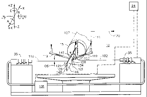
Illustrated in FIGS. 1 and 2 is a schematic illustration of a laser shock
peening
system 10 that is used to laser shock peen articles exemplified by a gas
turbine engine
rotor blade 108 having an airfoil 134 with a patch 145 that is to be laser
shock peened.
The laser shock peening system 10 includes a generator 31 having an oscillator
and a
pre-amplifier and a beam splitter which feeds the pre-amplified laser beam
into two
beam optical transmission circuits and optics 35 that transmit and focus low
energy
first and second laser beams 102 and 103, respectively. The blade 108 is
mounted in a
fixture 15 which is attached to a five-axis computer numerically controlled
(CNC)
manipulator 127, one of which is commercially available from the Huffman
Corporation, having an office at 1050 Huffman Way, Clover, SC 29710. The five
axes of motion that are illustrated in the exemplary embodiment are
conventional
translational axes X, Y, and Z, and conventional first, second, and third
rotational axes
A, B, and C, respectively, that are well known in CNC machining. The
manipulator
127 is used to continuously move and position the blade to provide laser shock
peening "on the fly" in accordance with one embodiment of the present
invention.
Laser shock peening may be done in a number of various ways using paint or
tape as
an ablative medium (see in particular U.S. Patent No. 5,674,329 entitled
"Adhesive
Tape Covered Laser Shock Peening").
7
CA 02398339 2002-08-15
13DV14256
Referring to FIGS. 5 and 6, the blade 108 includes an airfoil 134 extending
radially outward from a blade platform 136 to a blade tip 138. The blade 108
includes
a root section 140 extending radially inward from the platform 136 to a
radially inner
end 137 of the root section 140. At the radially inner end 137 of the root
section 140
is a blade root 142 which is connected to the platform 136 by a blade shank
144. The
airfoil 134 extends in the chordwise direction between a leading edge LE and a
trailing edge TE of the airfoil. A chord CH of the airfoil 134 is the line
between the
leading edge LE and trailing edge TE at each cross-section of the blade as
illustrated
in FIG. 6. A pressure side 146 of the airfoil 134 faces in the general
direction of
rotation as indicated by an arrow V and a suction side 148 is on the other
side of the
airfoil. A mean-line ML is generally disposed midway between the two sides in
the
chordwise direction.
The leading edge section 150 of the blade 108 extends along the leading edge
LE of the airfoil 134 from the blade platform 136 to the blade tip 138. The
leading
edge section 150 includes a predetermined first width W such that the leading
edge
section 150 encompasses an area where nicks 54 (shown in phantom) and tears
that
may occur along the leading edge of the airfoil 134 during engine operation.
The
airfoil 134 subject to a significant tensile stress field due to centrifugal
forces
generated by the blade 108 rotating during engine operation. The airfoil 134
is also
subject to vibrations generated during engine operation and the nicks and
tears operate
as high cycle fatigue stress risers producing additional stress concentrations
around
them.
To counter fatigue failure of portions of the blade along possible crack lines
that can develop and emanate from the nicks and tears, the laser shock peened
patch
145 is placed along a portion of the leading edge LE where incipient nicks and
tears
may cause a failure of the blade due to high cycle fatigue. The laser shock
peened
patch 145 is placed along a portion of the leading edge LE where an exemplary
predetermined first mode line LM of failure may start for a fan or compressor
blade.
8
CA 02398339 2002-08-15
13DV 14256
Within the laser shock peened patch 145, at least one and preferably both the
pressure
side 146 and the suction side 148 are simultaneously laser shock peened to
form first
and second oppositely disposed laser shock peened surface portions 152 and 153
and
a pre-stressed blade regions 156 and 157, respectively, having deep
compressive
residual stresses imparted by laser shock peening (LSP) extending into the
airfoil 134
from the laser shock peened surfaces as seen in FIG. 6. The pre-stressed blade
regions
156 and 157 are illustrated along only a portion of the leading edge section
150 but
may extend along the entire leading edge LE or longer portion thereof if do
desired.
The low energy first and second laser beams 102 and 103, respectively, are
arranged to simultaneously laser shock peen longitudinally spaced apart
opposite
convex suction and concave pressure sides 148 and 146, respectively, along a
leading
edge LE of an airfoil 134 of the blade 108 within the patch 145. The method
form
pairs or couples of first and second laser shock peened spots 158 and 159,
respectively, wherein the pair of spots are longitudinally spaced apart a
longitudinal
distance LD and transversely offset from each other as indicated by a
transverse offset
OS with respect to the longitudinal distance as more particularly shown in
FIG. 3.
The convex suction and concave pressure sides 148 and 146 have first and
second laser shock peening surfaces 152 and 153, respectively, within the
patch 145
on opposite sides of the blade 108. The first and second laser shock peening
surfaces
152 and 153, respectively, are covered with an ablative coating such as paint
or
adhesive tape to form a coated surface as disclosed in U.S. Patent Nos.
5,674,329 and
5,674,328. The paint and tape provide an ablative medium over which is placed
a
clear containment media which is typically a clear fluid curtain such as a
flow of
water 121.
The blade 108 is continuously moved during the laser shock peening process,
while, the laser shock peening system 10 is used to continuously
simultaneously firing
the stationary first and second laser beams 102 and 103 through the curtain of
flowing
water 121 on the coated first and second laser shock peening surfaces 152 and
153
9
CA 02398339 2002-08-15
13DV 14256
forming the laser shock peening spots 158. The curtain of water 121 is
supplied by a
water nozzle 123 at the end of a water line 119 connected to a water supply
pipe 120.
A controller 24 that is used to monitor and/or control the laser shock peening
system
10.
The embodiment illustrated in FIGS. 1 and 2 uses longitudinally parallel and
transversely spaced apart low energy first and second laser beams 102 and 103
that
are set up or aimed such that first and second centerlines CL 1 and CL2 of the
first and
second laser beams, respectively, impinge first and second surface portions
referred to
herein as first and second surface portions 152 and 153, respectively, within
the patch
145 on the opposite convex suction and concave pressure sides 148 and 146 of
the
airfoil 134. The first and second laser beams 102 and 103 are then
simuitaneously
fired with sufficient energy to vaporize material on the first and second
surface
portions 152 and 153 to form first and second regions having deep compressive
residual stresses extending into the airfoil 134 of the blade 108 or other
article from
the first and second laser shock peened surface portions, respectfully.
The first and second laser beams 102 and 103 are aimed such that the first and
second centerlines CL1 and CL2 impinge the first and second surface portions
152
and 153 at first and second laser beam centerpoints Al and A2 through which
pass
parallel first and second axes AXI and AX2 that are substantially normal to
the first
and second surface portions at the first and second laser beam centerpoints,
respectfully, and such that the first and second axes that are offset a
transverse offset
OS as further illustrated in FIG. 3. In one embodiment, good results were
obtained
using an approximately .075 inch offset OS and a circular spot diameter D
equal to
about .25 inches. Other tests having good results were made with .100, .120,
.150,
and .187 inch offsets OS using flat rectangular coupons to simulate the
leading edge
of an airfoil.
Illustrated in FIG. 4 is another embodiment of the present invention in which
the first and second laser beams 102 and 103 are aimed such that the first and
second
CA 02398339 2002-08-15
13DV14256
centerlines CL1 and CL2 intersect at an apex 90 and are angled with respect to
each
other and form first and second angles 94 and 96 with parallel first and
second axes
AXl and AX2 that are substantially normal to the first and second surface
portions
152 and 153 at first and second laser beam centerpoints Al and A2,
respectfully. One
currently used laser shock peening system impinges its laser beams with six
degree
angle off a normal to the article's laser shock peening surface. The article
or blade is
fed into a crossing point of the beams where the beams' centerlines cross at
the apex
as indicated by the blade drawn in phantom line 98. When the article is fed to
the
crossing point, the first and second laser shock peened spots 158 and 159 are
formed
on both sides simultaneously and are centered along the same longitudinal path
or, in
other words, the first and second axes AX1 and AX2 are collinear. For the
present
invention, the blade is fed longitudinally offset to the side of one of the
laser beams
and then the laser spots from both sides are formed at different longitudinal
path and
the first and second axes AXl and AX2 are transversely offset and non-
collinear.
In general but not necessarily, the first and second surface portions 152 and
153 and hence the first and second laser shock peened spots 158 and 159 are
substantially parallel. The first and second laser shock peened spots 158 and
159 are
illustrated as being circular, however, they may have elliptical, oval, or
other shapes.
The present invention includes a laser shock peened article having laser shock
peened
first and second surface portions 152 and 153, respectively. First and second
regions
156 and 157 having deep compressive residual stresses extend into the blade
108 from
the first and second laser shock peened surface portions, respectfully.
Couples 88 of
simultaneously laser shock peened first and second spots 158 and 159,
respectively,
are longitudinally spaced apart the longitudinal distance LD and formed by the
laser
shock peening process on the first and second surface portions 152 and 153
such that
each of the simultaneously laser shock peened first and second spots in a
given couple
have a transverse offset OS from each other with respect to the longitudinal
distance.
11
CA 02398339 2002-08-15
13DV 14256
The low energy first and second laser beams 102 and 103 have low energy
levels on the order of 3-10 joules or even perhaps 1-10 joules to allow
smaller less
expensive lasers to be used as disclosed in United States Patent No.
5,932,120,
entitled "Laser Shock Peening Using Low Energy Laser". An energy level range
of
about 3-7 joules has been found particularly effective as has a level of about
3 joules.
The low energy level laser beams are focused to produce the small diameter
first and
second circular laser spots 158 and 159 having a diameter D in a range of
about 1 mm
(0.040 in.) to 2 mm (0.080 in.). The area of the spots are about .79 - 3.14
square
millimeters or about .00 13 - 0050 square inches. The lower energy range has
shown
very good results and the 3 joules laser is quite adequate, produces good
laser shock
peening results, and is very economical to use, procure, and maintain. These
energy
ranges result in surface laser energy densities of approximately between 400
joules/(square cm) down to 100 joules/(square cm), respectively.
FIG. 7 illustrates 9 overlapping rows R, more or fewer rows may be used, of
the overlapping first laser shock peening spots 158 and one embodiment of the
present
invention adjacent ones of the laser shock peening spots 158 are laser shock
peened
on different passes and the patch 145 may be re-coated between the passes.
Adjacent
ones of the rows R of the overlapping laser shock peening spots 158 and
adjacent ones
of the overlapping laser shock peening spots typically having an overlap of
about 30%
and the laser shock peening spots are typically about .25 inches.
Thus, the first and second laser beams 102 and 103 are aimed and fired in a
manner to produce first and second patterns on the first and second surface
portions
152 and 153, respectively, of the article having overlapping adjacent rows of
overlapping adjacent one of the first and second spots, respectively. In a
more
particular embodiment, the first and second patterns are formed by
continuously
moving the article while holding stationary and continuously firing the laser
beams
with repeatable pulses with relatively constant periods between the pulses,
wherein
the surface portions are laser shock peened using sets of first through fourth
sequences
12
CA 02398339 2005-07-14
13DV14256
S1 through S4, respectively. Each of the first through fourth sequences S1-S2
includes continuously firing the laser beams on the surface portions such that
on each of the surface portions adjacent ones of the laser shock peened
spots are hit in different ones of the sequences in the sets. More than one
set
may be used such that each spot is hit with a laser beam more than once. A
more particular embodiment includes coating the surface portions with an
ablative coating before and in between each of the sequences in the set.
The present invention has been described in an illustrative manner.
It is to be understood that the terminology which has been used is intended to
be in the nature of words of description rather than of limitation. While
there
have been described herein, what are considered to be preferred and
exemplary embodiments of the present invention, other modifications of the
invention shall be apparent to those skilled in the art from the teachings
herein
and, it is, therefore, desired to be secured in the appended claims all such
modifications as fall within the true spirit and scope of the invention.
-13-