Note : Les descriptions sont présentées dans la langue officielle dans laquelle elles ont été soumises.
CA 02399386 2002-07-24
WO 01/56644 PCT/US01/01620
1
1 TITLE: Angioplasty Device and Method of Making Same
TECHNICAL FIELI)
This invention relates to an angioplasty device for compressing and/or
removing
atherosclerotic plaques, thromboses, stenoses, occlusions, clots, potential
embolic
material and so forth (hereinafter "obstructions") from veins, arteries,
vessels, ducts and
the like (hereinafter "vessels"). More particularly, the invention relates to
a total capture
angioplasty device and trap capable of use in small and large diameter vessels
and vessel-
like structures.
BACKGROUND
Angioplasty devices are used to treat a wide variety of conditions and to
perform a
wide variety of procedures, including without limitation: congenital or
acquired stenoses
or obstructions; percutaneous aspiration thromboembolectomy; cerebral
embolization;
congenital or acquired obstruction or stenosis of the aorta, renal, coronary,
pulmonary,
iliac, femoral, popliteal, peroneal, dorsalis pedis, subclavian, axillary,
brachial, radial,
ulnar, vertebral, cerebral and/or cerebellar artery or any other accessible
artery or their
ramifications; congenital or acquired obstruction or stenosis of the superior
vena cava,
inferior vena cava, common iliac, internal iliac, external iliac, femoral,
greater saphenous,
lesser saphenous, posterior tibial, peroneal, popliteal, pulmonary, coronary,
coronary
sinus, innominate, brachial, cephalic, basilic, internal jugular, external
jugular, cerebral,
cerebellar, sinuses of the dura mater and/or vertebral vein or any other
accessible vein or
their ramifications; atheromatous lesions of any graft or its ramifications;
obstructions or
stenoses of connections between and among grafts, veins, arteries, organs and
ducts; vena
caval bleeding; congenital or acquired intracardiac obstructions, stenoses,
shunts and/or
aberrant communications; congenital or acquired cardiovascular obstructions,
stenoses
CA 02399386 2002-07-24
WO 01/56644 PCT/US01/01620
2
and/or diseases; infusion of thrombolytic agents; thromboembolic phenomena;
diagnostic
catheterization; removal of clots; intrahepatic and/or extrahepatic biliary
ductal
obstructions (e.g., stones, sediment or strictures); intravascular,
intracardiac and/or
intraductal foreign bodies; renal dialysis; congenital and acquired esophageal
and/or
gastrointestinal obstructions and/or stenoses; non-organized atheromata;
dialysis fistula
stenosis; ruptured cerebral aneurysm; arterio-arterial, arteriovenous and/or
veno-venous
fistulae; ureteral obstructions (e.g., stones, sediment or strictures);
fibromuscular
dysplasia of the renal artery, carotid artery and/or other blood vessels;
and/or
atherosclerosis of any accessible artery, vein or their ramifications. Such
procedures may
be performed in both humans and in other applications.
Conventional angioplasty devices generally consist of a catheter containing a
balloon-like member that is inserted into an occluded vessel. Expansion of the
balloon at
the obstruction site crushes the obstruction against the interior lining of
the vessel. When
the balloon is retracted, the obstruction remains pressed against the vessel
wall and the
effective diameter of the vessel through which fluid may flow is increased at
the site of
the obstruction. Examples of angioplasty devices incorporating a balloon are
shown in
U.S. Pat. Nos. 4,646,742; 4,636,195; 4,587,975; and 4,273,128.
Other conventional angioplasty devices have been developed that incorporate
expandable meshes or braids, drilling or cutting members, or lasers as a means
for
removing an obstruction. Examples of these angioplasty devices are illustrated
by U.S.
Pat. Nos. 4,445,509; 4,572,186; 4,576,177; 4,589,412; 4,631,052; 4,641,912;
and
4,650,466.
Many problems have been associated with these angioplasty devices. Perhaps the
most significant problem is the creation of particulate matter during the
obstruction
CA 02399386 2002-07-24
WO 01/56644 PCT/US01/01620
3
removal procedure. Recent ex vivo studies have demonstrated that huge numbers
of
emboli are produced on inflation and on deflation of the angioplasty balloon
during
dilation of a stenotic lesion. See Ohki T. Ex vivo carotid stenting,
(Presentation) ISES
International Congress XI, Feb 11, 1998. These particles are released into the
fluid
flowing through the vessel and can lead to emboli, clots, stroke, heart
failure,
hypertension and decreased renal function, acute renal failure, livedo
reticularis and
gangrene of the lower extremities, abdominal pain and pancreatitis, cerebral
infarction
and retinal emboli, tissue injury, tissue death, emergency bypass surgery,
death and other
undesirable side effects and complications. Regardless of the type of
angioplasty device
used, a substantial number of particles will be generated.
Even very small particles can cause significant harm. The cross-sectional
diameter of normal capillaries varies for different parts of the body and may
be comprised
of vessels as small as 2.0-3.5 ,u for very thin capillaries or 3.5-5.0 ,u for
moderately thin
capillaries. Accordingly, any particles that exceed these sizes can lodge
inside the vessel.
Furthermore, in the case of the heart, approximately 45% of the capillaries
are closed at
any given time, so that any particle, no matter how small, dislodged into this
organ is
liable to capture. Accordingly, it has become apparent that distal
embolization presents a
formidable threat.
One partial solution to the above-noted problems is disclosed in U.S. Patent
No.
4,794,928 to Kletschka. This angioplasty device incorporates a trap/barrier
for trapping
and removing particles that break away from the treatment sight. This device
is desirable
because it can prevent physiologically significant particles from escaping
from the
obstruction site, thus preventing the occurrence of unfavorable side effects
from
angioplasty treatment and procedures. One problem with this design, however,
is that it is
CA 02399386 2002-07-24
WO 01/56644 PCT/US01/01620
4
difficult to simultaneously provide an angioplasty device that is small enough
to be used
in very small and medium sized arteries, and/or in severely occluded vessels
(i.e., vessels
having a 90% or greater stenosis), and that has sufficient suction to remove
the particulate
matter.
Another partial solution to the above noted problems uses multiple catheters.
These devices require that the doctor first deliver a "blocking" catheter to
the target region
such that its occlusion balloon is distal to the treatment site. The doctor
then loads a
second "balloon" catheter over the blocking catheter and performs the
angioplasty
procedure. The second catheter is then removed and a third catheter is loaded
in its place
over the blocking catheter. The third catheter can be used to aspirate blood
from the
treatment site. One problem with this design, however, is that it does not
provide a means
for capturing particles that are too large to fit within the suction lumen.
Another problem
is that this design requires a complex and relatively lengthy operational
procedure, which
can lead to neurological complications. In addition, particulate matter may
also escape or
be pulled from the treatment site when the catheters are switched and when the
blocking
balloon is deflated. Even when combined with suction, the risk exists that
particles too
large to be removed through the suction conduit will be delivered distally
from the
forward thrust of the blood flow as the blocking balloon is deflated.
Still another partial solution uses a porous hood that allows blood to pass.
The
hood, attached to the guidewire with struts, is held in a collapsed state
within the
angioplasty catheter. The hood deploys when pushed beyond the tip of the
restraining
catheter. Withdrawing the hood within the catheter closes the trap. These
devices,
however, do not provide suction and require multiple catheters. In addition,
small
particles may pass through the porous hood.
CA 02399386 2002-07-24
WO 01/56644 PCT/US01/01620
Fig. 1 illustrates the problems associated with obtaining the size of conduits
necessary to do just the desired insertion, inflation, and suction tasks. Fig.
1 is a cross
section of a five French catheter 10. A standard, 150 centimeter long,
catheter may need a
suction lumen 12 with a diameter of about 0.025 inches in order provide
sufficient suction
5 at its operational end to cope with debris released from a large
atheromatous plaque. The
catheter may also require an inflation/deflation lumen 14 with a diameter of
about 0.015
inches to inflate an angioplasty balloon and a centered guidewire lumen 16
having a
diameter of about 0.035 inches to position the device. As can be seen, these
lumens
significantly interfere with each other. An additional mechanism to open and
close a
blocking/capturing device will further encroach on allocatable space.
Clearly, there is a need for an improved angioplasty device for use in small
diameter and/or severely occluded vessels that can prevent substantially all
physiologically significant particles from escaping from the obstruction site,
thus
preventing the occurrence of unfavorable side effects from the angioplasty
treatment and
procedures. There is also a need for a small diameter angioplasty device that
can provide
aspiration, blocking, and capturing capabilities. In addition, there is a need
for an
improved particle trap that can prevent substantially all physiologically
significant
particles from escaping from the obstruction site and that can fit within, and
be actuated
by, a small diameter catheter bundle.
SUMMARY
The present invention provides an apparatus for use in angioplasty procedures
or
other medical, veterinary, non-medical or industrial applications where
removal of an
obstruction from a vessel or vessel-like structure could produce particles,
which, if
allowed to remain in the vessel, could cause undesirable complications and
results. The
CA 02399386 2002-07-24
WO 01/56644 PCT/US01/01620
6
present invention is particularly suited for use in small diameter vessels
and/or in severely
occluded vessels because it maximizes suction for a given catheter diameter.
The present
invention can also prevent substantially all physiologically significant
particles from
escaping from the obstruction site. Particles smaller than the width of the
suction lumen
are removed by aspiration in some embodiments, while the larger particles are
captured
beneath a contractible hood and removed when the catheter is withdrawn. Some
embodiments also have a provision for aspirating debris generated as the
angioplasty
device is insinuated through a stenosis.
One aspect of the present invention is an angioplasty device for removing an
obstruction from a vessel or vessel-like structure. One embodiment of this
angioplasty
device comprises a catheter for insertion into a vessel-like structure and a
trap operably
connected to the catheter and to a rotatable member, such as a fixed guidewire
or a
catheter, wherein a rotation of the rotatable member relative to the catheter
actuates the
trap. Some embodiments of this angioplasty device may also comprise a flexible
strut
fixedly connected to the catheter and to the trap. This flexible strut may
expand and
contract the trap by moving between a helically twisted position and an
arcuately
expanded position.
Another aspect of this invention is a trap for selectively blocking a vessel
or
vessel-like structure. One embodiment comprises a rotatable member, such as a
fixed
guidewire or a catheter, that actuates a flexible strut between an arcuately
expanded
position and a helically twisted position, and a membrane operably connected
to the
flexible strut. These embodiments may further comprise a first ring that
fixedly connects
the rotational member to the flexible strut and a second ring that fixedly
connects the
CA 02399386 2002-07-24
WO 01/56644 PCT/US01/01620
7
flexible strut to a catheter. In addition, the proximal portion of the
flexible struts can be
inserted into the wall of the catheter in place of or in addition to the
second ring.
Another aspect of the present invention is a method of making a particle trap
adapted for removing an obstruction from a vessel-like structure. One
embodiment
comprises the acts of operably connecting a plurality of flexible struts to an
outer surface
of a catheter, the catheter containing a rotatable member; operably connecting
the
plurality of flexible struts to the rotatable member; and operably connecting
a membrane
to the plurality of flexible struts.
Another aspect of the present invention is a device for removing an
obstruction
from a vessel-like structure. One embodiment comprises a catheter for
insertion into a
vessel-like structure, the catheter having a catheter wall and a moveable
member, and a
trap operably connected to the catheter wall and to the moveable member.
Relative
motion between the catheter wall and the moveable member actuates the trap.
This
relative motion may be a relative rotation or a relative translation.
Another aspect is a catheter bundle for insertion into a vessel-like
structure. The
catheter bundle in this embodiment defines a balloon adapted to compress an
obstruction
against the vessel-like structure; a trap adapted to selectively block the
vessel-like
structure; an inflation lumen in operable communication with the balloon; and
a suction
lumen in operable communication with the trap. This catheter bundle has a
diameter of
less than about twenty French, with some embodiments having a diameter of less
than
about five French.
Another aspect of the present invention is a type of angioplasty procedure.
One
embodiment of this procedure comprises the acts of inserting a catheter into
the vessel-
like structure, the catheter including a trap and an actuator; positioning the
trap in a
CA 02399386 2002-07-24
WO 01/56644 PCT/US01/01620
8
downstream direction from an obstruction; moving the actuator in a first
direction,
thereby opening the trap; and moving the actuator in a second direction,
thereby closing
the trap. This procedure may further comprise the act of removing the
obstruction from
the vessel-like structure, thereby producing at least one particle. The at
least one particle
may be removed from the vessel-like structure using a suction lumen, the trap,
or a
combination thereof.
Three additional aspects of the present invention are a modular trap for an
angioplasty device, a guidewire for use in a medical device, and an
angioplasty device
having a valve. One modular trap embodiment comprises a trap adapted to
selectively
block a vessel-like structure; and a coupling device that couples the trap to
the angioplasty
device. One guidewire embodiment comprises a guidewire wall defining a
proximal
opening, a distal opening, and an annular passageway, wherein the annular
passageway
fluidly connects the proximal opening to the distal opening. One angioplasty
device
embodiment with a valve comprises a first lumen, and a valve adapted to
selectively
block the first lumen.
Another aspect of the present invention is an apparatus for insertion into a
vessel-
like structure over a guidewire. One embodiment comprises a catheter for
insertion into a
vessel-like structure, the catheter having a catheter wall and a moveable
member, and a
trap operably connected to the catheter wall and to the moveable member,
wherein
relative motion between the catheter wall and the moveable member actuates the
trap.
The catheter in this embodiment includes a guidewire lumen adapted to
slideably receive
the guidewire.
The present invention also includes a method of making an angioplasty device
suitable for over the wire procedures. One embodiment comprises forming a
catheter
CA 02399386 2006-06-07
9
having a first wall and a second wall, operably connecting a plurality of
flexible struts to the
first wall, operably connecting the plurality of flexible struts to the second
wall, and
operably connecting a membrane to the plurality of flexible struts. The first
wall in this
embodiment defines a guidewire lumen and cooperates with the second wall to
define a
fluid communication lumen.
One or more of these embodiments may be used to remove an obstruction from a
vessel-like structure by inserting the guidewire into a vessel-like structure;
inserting a
catheter into the vessel-like structure over the guidewire, the catheter
including a trap and an
actuator; positioning the trap in a downstream direction from an obstruction;
moving the
actuator in a first direction, thereby opening the trap; and moving the
actuator in a second
direction, thereby closing the trap.
One feature and advantage of the present invention is that it can provide a
small
diameter angioplasty device that can trap and remove substantially all
physiologically
significant particles. Another feature and advantage of the present invention
is that it can
provide aspiration, blocking, and capturing capabilities in a single catheter.
Yet another
feature and advantage is that the present invention maximizes the amount of
suction per unit
size, thus providing the doctor with more suction in larger vessels than
presently available.
These and other features, aspect, and advantages of the present invention will
become better
understood with preference to the following description, appended claims, and
accompanying drawings.
In one aspect, the present invention resides in an apparatus for insertion
into a
vessel-like structure over a guidewire, comprising: a catheter for insertion
into a vessel-like
structure, the catheter having a catheter wall and a moveable member, and
defining a
guidewire lumen adapted to slideably receive a guidewire; and a trap operably
connected to
the catheter wall and to the moveable member, wherein relative motion between
the catheter
wall and the moveable member actuates the trap.
In another aspect, the present invention resides in an angioplasty device for
insertion
over a guidewire, comprising: (a) a first catheter wall defining a guidewire
lumen, the
guidewire lumen being adapted to slideably receive the guidewire; (b) a second
catheter
wall that cooperates with the first catheter wall to define a suction lumen;
(c) a third catheter
wall that cooperates with the second catheter wall to define an
inflation/deflation lumen; (d)
CA 02399386 2006-06-07
9a
a balloon fluidly connected to the inflation/deflation lumen; (e) a trap
fixedly connected to
the first catheter wall and to the second catheter wall, whereby relative
motion between the
first catheter wall and the second catheter wall actuates the trap; and (f) at
least one suction
aperture fluidly connected to the suction lumen.
In another aspect, the present invention resides in a method of making an
angioplasty device, comprising: forming a catheter having a first wall and a
second wall,
wherein the first wall defines a guidewire lumen; operably connecting a
plurality of flexible
struts to the first wall; operably connecting the plurality of flexible struts
to the second wall;
and operably connecting a membrane to the plurality of flexible struts.
In another aspect, the present invention resides in a device for acting on an
obstruction in a vessel-like structure, the device comprising: a catheter for
insertion into the
vessel-like structure, the catheter having a suction lumen; an operative
member operably
connected to the catheter and adapted to remove or compress the obstruction; a
plurality of
flexible struts connected to the catheter and to a guidewire, whereby rotation
of the
guidewire relative to the catheter twists the plurality of flexible struts
between an arcuately
expanded position and a helically twisted position; a membrane operably
connected to the
plurality of flexible struts to define a trap; at least one suction aperture
operably connected
to the suction lumen; and a valve located in the suction lumen for controlling
a suction force
at the suction aperture.
In another aspect, the present invention resides in a device for capturing
particles
flowing through a vessel or vessel like-structure, the device comprising: a
catheter for
insertion into the vessel, the catheter having a suction lumen; a plurality of
flexible struts
having a first end connected to the catheter and a second end connected to a
guidewire, the
struts having a contracted position wherein the struts are helically twisted
around the
catheter and an expanded position wherein the struts extend arcuately outward
from the
catheter; a membrane connected to the plurality of flexible struts to define a
trap; and an
actuation mechanism coupling the guidewire to the catheter for causing a
combined rotation
and longitudinal motion of the guidewire; wherein the suction lumen has a
distal aperture
and at least one suction aperture located on a peripheral wall thereof, the
apertures are being
located within the trap to allow removal of material therein.
CA 02399386 2006-06-07
9b
In yet another aspect, the present invention resides in a device for capturing
particles
flowing through a vessel, the device comprising: a catheter for insertion into
the vessel, the
catheter having a longitudinal lumen therein; a plurality of flexible struts
having a first end
connected to the catheter and a second end connected to a moveable member, the
struts
having a contracted position wherein the struts are helically twisted around
the catheter and
an expanded position wherein the struts extend arcuately outward from the
catheter; and a
membrane connected to the plurality of flexible struts to define a trap;
wherein, in the
contracted position, a longitudinal distance between the first and second ends
of the struts is
greater than the longitudinal distance in the expanded position; and wherein
the longitudinal
lumen has a distal aperture and at least one suction aperture located on a
peripheral wall
thereof, the apertures are being located within the trap to allow removal of
material therein.
In a further aspect, the present invention resides in a device for capturing
particles
flowing through a vessel, the device comprising: a catheter for insertion into
the vessel, the
catheter having a longitudinal lumen therein; a moveable member disposed
substantially
within the longitudinal lumen; and a plurality of flexible struts each having
a first end and a
second end, the first ends fixedly connected to the catheter by a first radial
ring, the second
ends connected to the moveable member by a second radial ring, the struts
having a
contracted position wherein the struts are helically twisted and an expanded
position
wherein the struts extend arcuately outward; wherein, when the struts
transition from the
contracted position to the expanded position, the second radial ring pivots
relative to the
first radial ring and moves closer to the first radial ring.
In yet a further aspect, the present invention resides in a device for
capturing
particles flowing through a vessel, the device comprising: a catheter for
insertion into the
vessel, the catheter having a longitudinal lumen therein; a moveable member
disposed
substantially within the longitudinal lumen; a plurality of flexible struts
each having a first
end and a second end, the first ends fixedly connected to the catheter by a
first radial ring,
the second ends connected to the moveable member by a second radial ring, the
struts
having a contracted position wherein the struts are helically twisted and an
expanded
position wherein the struts extend arcuately outward; wherein, when the struts
transition
from the contracted position to the expanded position, the second radial ring
pivots relative
to the first radial ring and moves closer to the first radial ring; and a
screw extension system
coupling the catheter and the moveable member, wherein the ratio between a
rotational and
CA 02399386 2006-06-07
9c
a longitudinal motion of the guidewire relative to the catheter is controlled
by a pitch of the
screw extension system.
BRIEF DESCRIPTION OF THE DRAWINGS
Figure 1(prior art) is a sectional view illustrating the size limits of a
conventional
five French catheter.
CA 02399386 2002-07-24
WO 01/56644 PCT/US01/01620
Figure 2 is a side view of one embodiment of the angioplasty device of the
present
invention.
Figures 3A - 3C are side plan views of different trap embodiments.
Figure 4 is a sectional view of the embodiment depicted in Figure 2 taken
along
5 the line AA.
Figure 5 is a side view of the distal end of the embodiment depicted in Figure
2.
Figure 6 is a sectional view of the embodiment depicted in Figure 5, taken
along
the line CC.
Figure 7A is a perspective view of an embodiment having a plurality of struts
in a
10 helically twisted position, with portions of the struts removed to show the
inner catheter
wall.
Figure 7B is a side plan view of an embodiment having a plurality of struts in
an
arcuately expanded position.
Figure 8 is a sectional view of a stiffener, taken along the line BB.
Figures 9A and 9B are a sectional view and a side plan view of an embodiment
having a screw extension system.
Figure 10 is a detailed side plan view of an embodiment having a flexible
membrane extension system.
Figure 1 1A is a side plan view of an embodiment capable of providing suction
during insertion.
Figures 11B and 11C are side plan views of two disks for use with the
embodiment in Figure 1 1A.
Figures 12A and 12B are sectional views of an alternate valve embodiment.
CA 02399386 2002-07-24
WO 01/56644 PCT/US01/01620
11
Figure 13 is a side plan view of an embodiment having separate catheters for
the
trap and the operative member.
Figure 14 is a sectional view of a trap catheter bundle embodiment configured
for
use in the antegrade direction.
Figure 15 is a sectional view of a trap catheter bundle embodiment configured
for
use in the retrograde direction.
Figure 16 is a sectional view of a trap catheter bundle embodiment configured
for
use in the antegrade direction, in which the trap is actuated by relative
motion between an
inner catheter wall and an outer catheter wall.
Figure 17 is a sectional view of a trap catheter bundle embodiment configured
for
use in the retrograde direction, in which the trap is actuated by relative
motion between an
inner catheter wall and an outer catheter wall.
Figure 18A is a sectional view of an angioplasty device embodiment configured
for use in the retrograde direction in which the trap is actuated by relative
motion between
an inner catheter wall and an outer catheter wall.
Figure 18B is a sectional view of an angioplasty device embodiment configured
for use in the antegrade direction in which the trap is actuated by relative
motion between
an inner catheter wall and an outer catheter wall.
Figure 19 is a sectional view of an angioplasty device embodiment having a
coupling device.
Figure 20 is a sectional view of the coupling device in Figure 19.
Figure 21 is a sectional view of a trap actuated by a relative translation,
showing
the trap in an arcuately expanded position.
CA 02399386 2002-07-24
WO 01/56644 PCT/US01/01620
12
Figure 22 is a sectional view of the trap in Figure 21, showing the trap in a
contracted position.
Figures 23A is a sectional view of a modular trap embodiment.
Figures 23B, 24A, and 24B are sectional views of alternate modular trap
embodiments.
Figure 25 is a sectional view of an embodiment having a hollow guidewire.
Figure 26 is a sectional view of an alternate embodiment having a hollow
guidewire.
Figure 27 is a sectional view of an embodiment in which a plurality of struts
connect a coupling device to the angioplasty catheter.
Figure 28 is a sectional view of the angioplasty device in Figure 5.
Figure 29 is a detailed sectional view of an alternate proximal end
embodiment.
Figure 30 is a sectional view of a modular trap embodiment having a guidewire
lumen.
DETAILED DESCRIPTION
Fig. 2 is a side plan view of one embodiment of the angioplasty device 20 of
the
present invention. This angioplasty device 20 comprises a flexible catheter 26
having a
proximal end 22, a distal end 24, and a generally circular cross section. The
proximal end
22 of the catheter 26 is connected to a branched housing 28 that contains a
suction port
30, an inflation port 32, and a guidewire port 34. The distal end 24 of the
catheter 26 is
connected to an angioplasty balloon 36, and a trap/barrier 38. As will be
described in
more detail with reference to Fig. 4, the flexible catheter 26 contains an
inflation/deflation
lumen 40, a suction/vacuum lumen 42, and a flexible guidewire 44.
CA 02399386 2002-07-24
WO 01/56644 PCT/US01/01620
13
In operation, distal end 24 of the angioplasty device 20 may be inserted into
a
vessel at any point in relation to the treatment site that is consistent with
the desired
treatment protocol. The balloon 36 is then aligned with the obstruction using
methods
known in the art, such as a radiopaque contrast solution, so that the trap 38
is situated in a
position downstream from the obstruction site with the opening of the trap 38
positioned
so that the fluid will flow into it and beneath the hood/membrane.
After positioning, the trap 38 may be expanded so that it forms a seal against
the
inner lining of the vessel. This seal will prevent physiologically significant
particles from
leaving the treatment site. A fluid, air, or other expansion medium may be
then injected
into the device 20 through the inflation port 32 and may be delivered through
the lumen
40 to the balloon 36. The balloon 36 may then be expanded to perform its
function.
Alternatively, the balloon 36 and the trap 38 may be expanded simultaneously
or the
balloon could be expanded before the trap 38. As the balloon 36 is expanded,
the
obstruction is crushed against the inner diameter of the vessel, which
increases the area
through which fluid can flow. Crushing of the obstruction, however, creates
particles that
may break free on either side of the balloon 36.
When the vessel is living tissue (e.g., a human or animal vein, artery or
duct) the
balloon 36 may be inflated to a pressure ranging from approximately three to
fifteen
atmospheres, or more, depending on the application. The proper pressure will
be
dependant on the treatment protocol, the type of organism being treated, the
type of vessel
being treated and the material from which the balloon is constructed.
Appropriate
expansion pressures for a given situation will be known to those skilled in
the art.
The balloon 36 may then be partially retracted so that a pressure differential
between the vessel and the suction lumen 42 can draw any resulting particles
toward the
CA 02399386 2006-06-07
14
trap 38. Particles are either drawn into and through the catheter 26 or lodged
in the trap
38 such that, when the trap 38 is retracted, the particles are trapped inside.
The trap 38 in this embodiment may assume any final shape as long as a
substantial seal is achieved with the inner lining of the vessel to be treated
and so long as
the shape facilitates entrapment of the particles. Figs. 3A - 3C show three
possible trap
38 embodiments. In particular, Fig. 3A shows a generally conically shaped trap
38, Fig.
3B shows a more or less "egg" shaped trap 38, and Fig. 3C shows a more or less
oval
shaped trap 38. Other trap 38 shapes and configurations are also within the
scope of the
present invention. In addition, the trap 38 and the balloon 36 may be situated
with respect
to each other in any configuration that allows the trap 38 to achieve a seal
with the inner
vessel lining and to trap particles when expanded. This includes, without
being limited
to, configurations in which the relative locations of the balloon 36 and the
trap 38 are
reversed. In contrast with the "antegrade" embodiments depicted in Figs. 2 and
3A-3C,
these "retrograde" embodiments would allow insertion of the angioplasty device
from a
point "downstream" from the treatment site.
Those skilIed in the art will recognize that the balloon 36 in this embodiment
serves as an operative member and may be replaced by any means known in the
art, or
later developed in the art, for removing or compressing an obstruction. Thus,
as used
throughout this specification and the claims, the terms "balloon" and
"operative member"
encompass any means for removing or compressing an obstruction, including but
not
limited to balloons, meshes, cutting rotors, lasers, treatment agents, and the
means
represented by U.S. Pat. Nos. 4,646,742, 4,636,195, 4,587,975, 4,273,128,
4,650,466,
4,572,186, 4,631,052, 4,589,412, 4,445,509, 4,641,912 and 4,576,177. Each type
of
operative member will have its
CA 02399386 2002-07-24
WO 01/56644 PCT/US01/01620
unique control mechanism that, in the case of a balloon, fills it or, in the
case of a laser or
cutting rotor, turns it on. Furthermore, although the balloon and its
associated filling or
expansion system will be used throughout the specification as an example of an
operative
member and its associated control means, it is to be understood that any
available
5 operative member and its control means could be substituted in many of the
embodiments
discussed herein. Thus, references to "expansion" and "retraction" of the
balloon should
be understood, by inference, to refer to activating and deactivating whatever
operative
member is incorporated into a given angioplasty device 20.
Fig. 4 is a sectional view of the catheter 26 in Fig. 2 taken along line AA.
The
10 catheter 26 includes an outer wall 46, the inflation/deflation lumen 40, an
inner wall 48,
the suction lumen 42, and the guidewire 44.
The inner wall 48 and the outer wall 46 may be made from any relatively
flexible
material. When used in medical applications it is desirable, however, that the
chosen
material be approved for use in medical devices, be compatible with standard
sterilization
15 procedures, and be able to withstand the balloon's 36 inflation pressure
without undue
expansion in the radial direction. One suitable material is nylon. However,
other wall
materials are within the scope of this invention. In some embodiments, the
inner wall 48
and the outer wal146 comprise the same material. These embodiments may be
desirable
because they are generally easier to manufacture. However, embodiments where
the inner
wall 48 is made from a different material than the outer wal146 are within the
scope of
this invention. In addition, the inner wall 48 may be reinforced in some
embodiments
with a metallic or plastic stent, strut, coil, or similar member, either in
sections or for the
full extent. These reinforcement members may also be embedded into the
catheter wall.
CA 02399386 2002-07-24
WO 01/56644 PCT/US01/01620
16
The relative sizes and positions of the outer wall 46, the inflation/deflation
lumen
40, the inner wall 48, the suction lumen 42, and the guidewire 44 are
arbitrary. However,
it is desirable to make the inflation/deflation lumen 40 and the suction lumen
42 as large
as possible so that they can provide greater suction to the distal end 24, and
ease of
inflation and deflation of the angioplasty balloon (when that is the operative
member).
That is, the maximum vacuum that may be applied through the suction port 30 is
limited
by the wall materials. This maximum available vacuum is reduced by frictional
losses
between the proximal end 22 and the distal end 24. Because frictional loses in
a closed
channel are inversely proportional to the channel's cross sectional area,
increasing the
cross sectional area will increase the vacuum available at the distal end 24.
One method of increasing the cross sectional areas of the inflation/deflation
lumen
40 and the suction lumen 42 is to make the outer wall 46, the
inflation/deflation lumen 40,
the inner wa1148, the suction lumen 42, and the guidewire 44 substantially
coaxial.
Coaxial arrangements can increase the available cross sectional area because,
for a circle:
dA =27cr . Thus, a lumen located near the outside of the catheter 26 will have
a larger
dr
flow area than will a lumen that is located near the interior of the catheter
26, even if both
lumens consume the same amount of distance between the walls. It was
discovered that
the increased flow area resulting from the coaxial arrangement can overcome
its increased
surface area.
Embodiments with coaxial lumens may be particularly desirable if the inner
wall
48 helps to form both the inflation/deflation lumen 40 and the suction lumen
42. These
embodiments are desirable because the catheter 26 only needs one internal
structure to
define two lumens. Despite these advantages, however, catheters having two or
more
CA 02399386 2002-07-24
WO 01/56644 PCT/US01/01620
17
inner walls are also within the scope of the present invention. These
embodiments may
be desirable because they can define additional lumens and can allow one
suction lumen
42 to physically move relative to the other inflation/deflation lumen 40.
Accordingly, in one five French catheter 26 embodiment having the coaxial
configuration shown in Fig. 4, the outer wall 46 has an outer diameter of
0.066 inches and
an inner diameter of 0.056 inches; the inner wall 48 has an outer diameter of
0.0455
inches and an inner diameter of 0.0355 inches; and the guidewire 44 has an
outer diameter
of 0.012 inches. This provides a suction lumen 42 with a cross sectional area
of about
0.0008 square inches. This embodiment is particularly desirable for use in
carotid arteries
procedures because it provides sufficient suction to remove the obstruction
before
complications occur and because it is small enough to fit within the artery.
Smaller
diameter catheters 26 (for example, between two and five French) having
smaller suction
lumens 42 may be suitable for use in less vital organs, where occlusion time
limits are
less critical, and in shorter catheters, where frictional losses are less
significant. Larger
diameter catheters 26 (for example, between five and forty French) having
larger suction
lumens 42 may be desirable for use in larger arteries, such as the aorta or
iliacs, to
accommodate the larger blood flow rate, and in longer catheters.
Figs. 5 and 28 are more detailed views of the distal end 24 of the embodiment
in
Fig. 2. Figs. 5 and 28 show that the inflation/deflation lumen 40 (see also
Fig. 4)
terminates in an opening 66 located inside the balloon 36. This opening 66
allows air,
saline solution, or some other inflation medium, to fill the balloon 36 and to
bias it
radially outward against the obstruction. Similarly, the suction lumen 42 (see
also Fig. 4)
terminates at a single opening 68 and/or a plurality of pores 69 that are
spaced along its
length and around its perimeter. These openings 68 and/or pores 69 are used to
remove
CA 02399386 2002-07-24
WO 01/56644 PCT/US01/01620
18
smaller particles from the treatment site and to suck larger particles into
the trap 38.
Embodiments in which the inflation/deflation lumen 40 terminates immediately
at the
proximal end of the balloon 36 may be particularly desirable because this
minimizes the
profile of the balloon 36 in its contracted configuration.
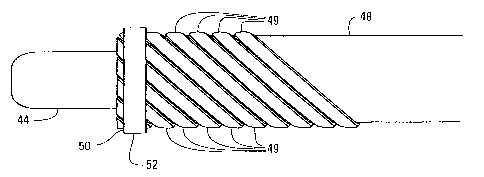
Figs. 5 and 28 also show that the trap 38 in this embodiment comprises a
plurality
of flexible struts 49 in an arcuately expanded position. In one embodiment,
these struts
49 are fixedly attached to the guidewire 44 by an inner stainless steel ring
50 and outer
stainless steel ring 52, and to the exterior surface of the interior wall 48
by a stainless steel
ring 54. A flexible membrane 56 having an open end 58 and a closed end 60 is
attached a
distal portion of the struts 49. Fig. 29 shows an alternate embodiment in
which the
branched housing 28 in Figs. 5 and 28 has been eliminated, with the guidewire
going
through an 0-ring seal 130 in the catheter's proximal end and an integral
suction port in
direct fluid communication with the suction lumen.
The plurality of flexible struts 49 and the flexible membrane 56 combine to
form
the trap 38. In some embodiments, flexible struts 49 are longer than the
distance between
the rings 50, 52 and the ring 54. This causes the flexible struts 49 to
function like a
single-leaf semi-elliptic beam spring when in their arcuately expanded
position. The open
end 58 of the flexible membrane 56 in this embodiment is attached to the
flexible struts
49 near their area of maximum axial extension. However, the membrane 56 could
also be
attached proximally or distally to the maximum extension point. The closed end
60 of the
flexible membrane 56 is attached to one of the rings 50 and 52. The flexible
struts 49 are
preferably radially spaced around the catheter 26 so that they can evenly bias
the
membrane 56 radially outward into contact with an interior wall of a vessel or
vessel-like
structure.
CA 02399386 2002-07-24
WO 01/56644 PCT/US01/01620
19
Rings 50 and 52 fixedly attach the distal end of the flexible struts 49 to the
guidewire 44. Similarly, ring 54 fixedly attaches the proximal end of the
flexible struts
49 to the exterior surface of the catheter's inner wall 48. Rotating the
guidewire 44
relative to the catheter 48 will cause the struts 49 to move between the
helically twisted
(or "braided") position shown in Fig. 7A and the arcuately expanded position
shown in
Fig. 7B. That is, rotating the guidewire 44 will cause the distal end of the
struts 49 to
rotate relative to the proximal end. Because the shortest distance between two
points is a
straight line, this rotation increases the distance between the proximal end
and the distal
end. This, in turn, forces the struts 49 to wrap around the inner wall 48 of
the catheter 26.
Continued rotation of the guidewire 44 will continue to draw the struts
radially inward
until they lie adjacent to the inner wall 48 of the catheter 26.
Rotating the guidewire 44 in the opposite direction will cause the struts 49
to
untwist, which allows the struts 49 to move back to the arcuately expanded
position
shown in Fig. 7B. This, in turn, expands the trap 38.
Fig. 8 is a sectional view of the angioplasty device 20 in Fig. 5 taken along
the line
BB. This figure shows four optional stiffening members 70 that connect the
inner wall 48
to the outer wal146. These stiffening members 70 define a plurality of
openings 72 that
keep the inflation/deflation lumen 40 (see Fig. 4) fluidly connected to the
balloon 36 (see
Figs. 5 and 28). These stiffening members 70 are desirable because they give
the user
something to "push against" when actuating the trap 38. That is, a user
expands and
contracts the trap 38 (see Figs. 5 and 28) by rotating the guidewire 44 around
its
longitudinal axis. The torque used to rotate the guidewire 44 is transferred
to the inner
wall 48 through the struts 49, which causes the inner wall 48 to twist. The
stiffening
members 70 couple the inner wall 48 and the outer wall 46. The combined
torsional
CA 02399386 2002-07-24
WO 01/56644 PCT/US01/01620
stiffness (or perhaps more accurately, the combined polar moment of inertia)
of the inner
wall 48 and the outer wal146 is greater than that of the inner wall 48 alone.
In this
embodiment, the stiffening members 70 may extend throughout the length of the
catheter
26 or may only extend a short distance from the opening 66.
5 Figs. 9A and 9B are side plan and sectional views of an angioplasty device
20
having a screw extension system 80 located near the distal end of the suction
lumen 42.
However, screw extension systems 80 located in other locations, such as within
the
housing 28, are also within the scope of the present invention. The screw
extension
system 80 in this embodiment comprises a helical screw thread 82 attached to
the
10 guidewire 44 and a pair of offset studs 84 attached to the inner wall 48.
The offset studs
84 engage the helical screw thread 82 without blocking the suction lumen 42,
which
causes the guidewire 44 to move axially inside the suction lumen 42 when
rotated.
Embodiments having this screw extension system 80 are desirable because it
increases the
distance between the distal rings 50 and 52 and the proximal ring 54 (see
Figs. 5 and 28),
15 which helps the struts 49 to contract into an orientation that is smooth
and tight against
the guidewire 44.
Fig. 10 shows a flexible membrane extension system 80a that may be used in
place of or in conjunction with the screw extension system 80 of Figs. 9A and
9B. Fig. 10
depicts the proximal end of the guidewire port 34, which comprises a generally
cylindrical
20 housing 86 and a generally cylindrical lumen 87 that is fluidly connected
to the suction
lumen 42 (see Fig. 4). The guidewire 44 runs through the lumen 87 and is
connected to a
disk shaped handle 88. Fig. 10 also depicts a flexible membrane 89 that is
attached to the
housing 86 and to the handle 88.
CA 02399386 2002-07-24
WO 01/56644 PCT/US01/01620
21
As described with reference to Figs. 7A and 7B, the user expands and contracts
the trap 38 by rotating the guidewire 44 around axis ZZ (see Fig. 10). The
guidewire 44,
in turn, may be rotated by manually turning the handle 88. Because the
membrane 89 is
fixed to both the housing 86 and the handle 88, however, this rotation causes
the
membrane 89 to twist. This twisting motion causes the membrane 89 to bunch
together,
which pulls the handle 88 in a distal direction towards the housing 86. The
handle 88, in
turn, pushes the guidewire 44 through the catheter 26.
Embodiments using the flexible membrane extension system 80a in Fig. 10 are
desirable because the membrane 89 longitudinally biases the proximal ring 54
relative to
the distal rings 50 and 52, thereby helping to actuate the trap 38, and
because the
membrane 89 helps to seal the suction lumen 42. Preferably, the membrane 89
will
comprise materials and dimensions such that the amount of rotation necessary
to actuate
the trap will also produce the desired longitudinal motion. Other extension
systems 80,
such as a spring-or other elastic member located between the handle 88 and the
housing
86, and other sealing systems, such as a membrane 89 that completely surrounds
the
handle 88, an 0-ring, or a wiper style seal, are also within the scope of the
present
invention.
Referring again to Fig. 5 and 28, the struts 49 may be made from any elastic
material. It is desirable, however, that the material be approved for use in
medical
devices when used in medical applications, have a relatively high modulus of
elasticity,
and have a relatively good resilience. One particularly desirable class of
materials are
"shape memory alloys," such as Nitinol . These materials are desirable because
they can
be easily "taught" a shape to which they will return after having been
deformed.
Manufacturers can use this feature to form struts 49 that will naturally
return to their
CA 02399386 2002-07-24
WO 01/56644 PCT/US01/01620
22
arcuately expanded position when a user releases the guidewire 44. Despite
these
advantages, however, other strut materials are within the scope of the present
invention.
This specifically includes, without being limited to, stainless steel and
polymers.
The guidewire 44 may be any device capable of guiding the catheter 26 into the
treatment site and capable of transmitting sufficient torque from the
guidewire port 34 to
the struts 49. The guidewire 44 in some embodiments is made from a braided
stainless
steel wire. These embodiments are desirable because stainless steel has
excellent strength
and corrosion resistance, and is approved for use in medical devices.
Stainless steel's
strength and corrosion resistance may be particularly desirable for use in
catheters having
diameters of five French or less. Despite these advantages, non-braided
guidewires 44;
guidewires 44 made from other materials, such as platinum or a polymer; and
embodiments having a removable guidewire 44 are within the scope of the
present
invention. The removable guidewire 44 in these embodiments may be operably
connected to the struts 49 by any suitable means, such as mechanical or
magnetic
linkages.
The guidewire 44 in some embodiments may taper along its length from a larger
diameter at the branching housing 28 to a smaller diameter at the trap 38.
These
embodiments are desirable because they help prevent the guidewire 44 and the
catheter 26
from "looping" around themselves during use. Looping is commonly observed in
phone
cords and occurs when a wire is twisted around its longitudinal axis. Despite
this
advantage, non-tapered guidewires 44 are also within the scope of the present
invention.
In some embodiments, as best shown in Fig. 6, the struts 49 are clamped to the
guidewire 44 by the rings 50 and 52. In these embodiments, the inner ring 50
is first
attached to the guidewire 44 by any suitable mechanical means, such as
swedging, press
CA 02399386 2002-07-24
WO 01/56644 PCT/US01/01620
23
fitting, or brazing. The struts 49 are then aligned over the inner ring 50 and
locked into
place by swedging, press fitting, brazing, or other suitable means the outer
ring 52 over
and around the struts 49. In some embodiments, the struts 49 are coated with a
material,
such as textured polyurethane, that helps to prevent the struts 49 from
slipping out of the
rings 50 and 52 and that helps to adhesively connect the struts 49 to the
membrane 56.
Ring 54 similarly clamps the proximal end of the struts 49 against the inner
wall 48 of the
catheter 26. The single ring 54 may be attached to the struts 49 by any
suitable means,
such as swedging, press fitting, or through use of adhesives.
The struts 49 may also be embedded into the inner wal148 of the catheter 26 or
may be inserted into longitudinal grooves formed into the inner wall 48 in
some
embodiments, or alternatively, the catheter 26 may be formed or over-molded
around the
struts 49. These features may be desirable for small diameter angioplasty
devices 20
because they may reduce the diameter of the ring 54 and because they may help
to lock
the struts 49 inside the ring 54. Inserting or embedding the struts 49 into
the wall of the
catheter can also eliminate the need for the ring 54.
Although stainless steel rings 50, 52, 54 are desirable to attach a Nitinol
strut 49 to
a stainless steel guidewire 44, those skilled in the art will recognize that
other means of
attaching the struts 49 are within the scope of the present invention. This
specifically
includes, without being limited to, rings 50, 52, 54 made from other
materials, such as
mylar, that can be bonded to the coating on the struts 49 and the use of
welding and/or
adhesives to directly bond the struts 49 to the guidewire 44 and/or the inner
wall 48.
These alternative methods may be particularly desirable when used with struts
49 that are
made from materials other than Nitinol and when the guidewire 44 is made from
materials
CA 02399386 2002-07-24
WO 01/56644 PCT/US01/01620
24
other than stainless steel. These alternate attachment means may also be
desirable for use
with the embodiments shown in Figs 14-30.
The number of struts 49 and their dimensions are arbitrary. However, more
struts
49 are generally desirable because they can more accurately bias the membrane
56 against
the vessel or vessel-like structure. It is also desirable that each strut 49
have dimensions
large enough that they can bias the membrane 56 against the vessel with
sufficient force
to prevent physiologically significant particles from escaping around the trap
38, but not
so large that the struts 49 will prevent capture of the particles or so large
that the struts 49
will interfere with each other when in their closed position. One suitable
five French
catheter 26 embodiment uses eight 0.006 inch x 0.003 inch Nitinol struts.
The membrane 56 may be any material capable of stopping physiologically
significant materials from leaving the treatment site when the trap 38 is
expanded. In
some embodiments, the membrane 56 is made from a relatively strong, non-
elastic
material. Non-elastic materials are desirable because they do not counteract
the radially
outward biasing force developed by the struts 49. In other embodiments, the
membrane
56 is made from an elastic or semi-elastic material, such as polyurethane,
polyester,
polyvinyl chloride, or polystyrene. These embodiments are desirable because
the
elasticity may help the struts 49 to close the trap 38. In still other
embodiments, the
membrane 56 is porous. These embodiments may be desirable because the pressure
developed by patient's heart will help deliver particles into the trap 38.
Fig. 11A shows an angioplasty device 20 capable of providing suction distal to
the
angioplasty device 20 while it is being inserted into the treatment site. In
this
embodiment, the ring 50 is replaced with a disk 92 attached to the inner
wal148 and a
disk 94 attached to the guidewire 44. These two disks 92 and 94 act as a valve
capable of
CA 02399386 2002-07-24
WO 01/56644 PCT/US01/01620
selectively permitting suction to that portion 99 of the vessel immediately in
front of the
angioplasty device 20. That is, as shown in Figs. 11B and 11C, each disk 92
and 94 has
two open portions 96 and two blocking portions 98. Rotation of the guidewire
44 causes
disk 94 to rotate relative to disk 92. This relative motion causes the disks
92 and 94 to
5 alternate between an "open" orientation in which the openings 96 in disk 92
are aligned
with the openings 96 in disk 94 and a "closed" orientation in which the
openings 96 in
disk 92 are aligned with the blocking portions 98 in disk 94. Preferably, the
same rotation
of the guidewire 44 used to toggle the disks 92 and 94 between their open and
closed
orientations also expands and contracts the trap 38.
10 In operation, the user would first rotate the guidewire 44 until the disks
92 and 94
are in the open orientation. In this orientation, the openings 96 cooperate to
create a fluid
communication channel between the suction lumen 42 and that portion 99 of the
vessel
immediately distal to the angioplasty device 20. This allows the user to
provide suction in
front of the angioplasty device 20 while the user inserts it into the vessel.
Once the
15 angioplasty device 20 is in place, the user will rotate the guidewire 44
until the disks are
in the closed orientation. In this orientation, the blocking portions 98
cooperate to prevent
fluid from flowing through the disks 92 and 94. This, in turn, creates suction
inside the
trap 38.
Figs. 12A and 12B show an angioplasty device 20 with an alternate valve
20 embodiment 120. This valve embodiment 120 comprises a disk shaped abutment
121 that
is rigidly attached to the catheter wa1148 and a stopper 122 that is rigidly
attached to the
guidewire 44 at a location distal to the abutment 121. The stopper 122 has a
conically
shaped surface 124 on its distal end and a generally planar engagement surface
126 on its
proximal end. The engagement surface 126 of the stopper 122 can selectively
plug a
CA 02399386 2002-07-24
WO 01/56644 PCT/US01/01620
26
circular flow channel 128 that is coaxially located in the abutment 121. The
valve 120
allows the user to apply suction to the portion 99 of the vessel immediately
in front of the
angioplasty device 20 through a hole 129 in the membrane 56.
In operation, the valve embodiment 120 is actuated by longitudinally moving
the
guidewire 44 relative to the catheter wall 48. That is, pulling the guidewire
44 in a
proximal direction relative to the catheter wall 48 causes the generally
planar engagement
surface 126 to sealably engage the abutment 121, which prevents fluid from
flowing
through the circular flow channel 128. Pushing the guidewire 44 in a distal
direction
relative to the catheter wall 48 causes the stopper 122 to disengage from the
abutment
121, which allows fluid to flow through the circular flow channel 128.
Other valve embodiments 120 capable of being actuated by longitudinal motion
are also within the scope of the present invention. For example, the stopper
122 may be
rotated 180 degrees so that the conically shaped surface 124 engages the
abutment 121,
rather than the generally planar engagement surface 126. These embodiments may
be
desirable because the conically shaped surface 124 will self-center the
stopper 122 in the
flow channel 128. Also, the stopper 122 may be located proximal to the
abutment 121.
In addition, the stopper 122 may have other shapes, such as a sphere or a
cylinder.
Those skilled in the art will recognize that the valve 120 and the disks 92,
94 can
be eliminated in these embodiments, which allows the suction lumen 42 to
simultaneously
provide suction under the trap 38 and distal to the angioplasty device.
Fig. 13 shows an embodiment where the balloon 36 and the trap 38 are
associated
with separate catheter bundles. That is, Fig. 13 shows an embodiment of the
present
invention comprising a trap catheter bundle 100 for the trap 38 and a balloon
catheter
bundle 102 for the balloon. In operation, the trap catheter bundle 100 is
inserted into
CA 02399386 2002-07-24
WO 01/56644 PCT/US01/01620
27
vessel until the trap 38 is situated distal to the obstruction site. The
balloon catheter
bundle 102 is then loaded over the trap catheter bundle 100 and used to remove
the
obstruction. This balloon catheter bundle 102 should have a centrally located
lumen 104
having an interior diameter larger than the trap catheter bundle 100.
Alternatively, the
balloon catheter bundle 102 or other device (such as an angioscope) may be
delivered to
the treatment area through a lumen 150 and an opening 152 in the trap catheter
bundle
100 (see Figs. 16-18).
Figs. 14 and 15 are sectional views of two trap catheter bundle embodiments
100.
Specifically, the trap catheter bundle 100 in Fig. 14 is configured to be
inserted in an
antegrade direction (i.e., in same the direction as the fluid flow) along a
guidewire 44.
Thus, the opening 58 in its membrane 38 faces towards its proximal end. The
opening 58
in Fig. 15, in contrast, faces the catheter's distal end because this catheter
bundle 100 is
configured to be inserted in a retrograde direction (i.e., with insertion site
"downstream"
in relation to the direction of fluid flow) along a guidewire 44. Both trap
catheter bundles
100 may be sized and shaped so that they can be inserted through the guidewire
channel
of a balloon catheter bundle 102. Those skilled in the art will recognize that
the trap
catheter bundle embodiments 100 in Figs. 14 and 15 can also be used to capture
embolic
debris without a balloon catheter bundle 102 and to deliver diagnostic and
therapeutic
agents to a treatment area.
Figs. 14 and 15 also show a seal 130 that may be used in place of or in
addition to
the flexible membrane extension system 80a depicted in Fig. 10 to prevent air
or other
fluid from leaking into the suction lumen 42. Accordingly, the seal 130 may be
any
device, such as an elastomeric 0-ring or wiper, that prevents fluid from
leaking through
the guidewire port 34 and that allows the guidewire 44 to move relative to the
catheter
CA 02399386 2006-06-07
28
wall 148. Embodiments using an 0-ring or a wiper style seal 130 are
particularly
desirable because the user can slide the guidewire 44 longitudinally relative
to the catheter
bundle 102 to help actuate the trap 38.
Figs. 16 and 17 are sectional views of two trap catheter bundle embodiments
100
in which the trap is actuated by relative motion between the inner catheter
wal148 and the
outer catheter wall 46. That is, the user actuates the trap 38 in this
embodiment by
rotating the inner catheter wall 48 relative to the outer catheter wall 46,
rather than
rotating a fixed guidewire 44 relative to the inner catheter wa1148. These
embodiments
are desirable because they can be loaded over a separate guidewire (not shown)
or
angioplasty device (not shown) that has previously been inserted into the
patient using
lumen 150 and opening 152. These embodiments are also desirable because inner
catheter wa1148 can be slid longitudinally with respect to the outer catheter
wall 46 to
help open and close the trap 38. In an appropriately designed balloon catheter
bundle,
these trap catheter bundles could be inserted through the lumen 150 of the
angioplasty
balloon catheter. Like the trap catheter bundle embodiments 100 in Figs. 14
and 15, the
trap catheter embodiments 100 in Figs. 16 and 17 can be inserted in either the
antegrade
or retrograde direction, and can be used with or without a separate balloon
catheter bundle
102.
Fig. 18A is a sectional view of an angioplasty device 20 embodiment for
use in retrograde applications (see Fig. 1 of U.S. Patent 4,794,928 for
conceptional
orientation. This embodiment comprises a separate catheter 160 for the balloon
36 and
for the inflation/deflation lumen 40. This catheter 160 has a first wall 162,
a second wall
163, and an end wall or plug 164. In operation, the trap 38 in this embodiment
is
actuated by relative rotational and/or
CA 02399386 2002-07-24
WO 01/56644 PCT/US01/01620
29
longitudinal motion between the exterior wall 46 and the first wall 162 of the
catheter
160.
Fig. 18B is sectional view of an angioplasty device 20 embodiment configured
for
use in the antegrade direction and for use with a pre-inserted guidewire. This
angioplasty
device 20 embodiment includes an inner wall 302, an intermediate wall 304, an
outer wall
306, and an end seal 307. The inner wall 302 forms a guidewire receiving lumen
150
having a shape and size suitable to slideably receive a guidewire 44. The
inner wall 302
and the intermediate wall 304 form a suction lumen 42, which is fluidly
connected to a
suction port 30 and a plurality of openings 68 and/or pores 69. The
intermediate wall 304
and the outer wall 306 form an inflation/deflation lumen 40, which is fluidly
connected to
the balloon 36. In operation, the trap 38 is actuated using relative
rotational and/or
longitudinal motion between the intermediate wall 304 and the inner all 302.
Like the embodiments in Figs. 16-17, 19 and 27, the angioplasty device
embodiments 20 in Figs. 18A and 18B are desirable because they may be loaded
over a
separate guidewire (not shown in Fig. 18A) or catheter (not shown) that has
previously
been inserted into the patient. In a typical over-the-wire surgical procedure,
a surgeon
may first insert a guidewire 44 into a vessel-like structure using a long
hypodermic needle
tube or other suitable device (not shown) until the guidewire 44 extends to a
desired point
past the obstruction. The surgeon then inserts the angioplasty device 20 over
the
guidewire 44 until the trap 38 is located downstream from the obstruction.
That is, the
surgeon slides the angioplasty device 20 down the guidewire 44 (with the
guidewire 44
sliding through the guidewire lumen 150) to the treatment site. After the
angioplasty
device 20 is properly positioned, the surgeon then performs the angioplasty
procedure as
previously described. These over-the-wire embodiments may be desirable for use
in
CA 02399386 2002-07-24
WO 01/56644 PCT/US01/01620
severely occluded vessels because the separate guidewire 44 is easier to
manipulate
through the obstruction and because many surgeons are experienced in inserting
and
manipulating the separate guidewire 44 into the proper position. Over-the-wire
embodiments are also desirable because the lumen 150 may be used to deliver
medicine,
5 blood, or other fluid past the obstruction during the procedure.
Fig. 19 is a sectional view of an angioplasty device embodiment having a
coupling
device 190 with four radially spaced sockets 189. Fig. 20 is a sectional view
of the
coupling device 190. The coupling device 190 in this embodiment may be any
device that
prevents the balloon catheter 102 from rotating relative to the trap catheter
bundle 100 (or
10 translating, if used with the trap embodiment 38 described with reference
to Figs. 21 and
22). These embodiments are desirable because the trap catheter bundle 100 and
the
balloon catheter bundle 102 may be manufactured separately, then combined as
needed.
Fig. 27 depicts an alternate embodiment in which a second group of struts 49a
connect the
coupling device 190 to an end 191 of the trap catheter bundle 100. In
operation, the trap
15 catheter bundles 100 in Figs. 19 and 27 may be inserted over an in-place
balloon catheter
102 and then either removed along with the balloon catheter 102 or by itself,
depending
on the configuration of the coupling devices 190. The embodiments in Figs. 19
and 27
may also be inserted over a guidewire 44 (not shown) or a may have a fixed
guidewire 44
extending distally from it.
20 Figs. 21 and 22 are sectional views of another trap catheter bundle
embodiment
100, in which the trap 38 is actuated by a translation between the guidewire
44 and the
catheter wall 148. In this embodiment, a first end 180 of the struts 49 is
connected to the
guidewire 44 and a second end 182 of the struts 49 is attached to the catheter
wall 148.
Translating the guidewire 44 (i.e., moving the guidewire in an axial
direction) relative to
CA 02399386 2002-07-24
WO 01/56644 PCT/US01/01620
31
the catheter wall 148 biases the first end 180 away from the end 182. This, in
turn,
actuates the struts 49 between an arcuately expanded position, such as that
shown in Fig.
21, and a contracted position, such as that shown in Fig. 22. Accordingly, the
struts 49 in
this embodiment remain generally parallel to the guidewire 44 throughout the
procedure.
Those skilled in the art will recognize that this actuation mechanism also
could be used
with the embodiments described with reference to Figs. 1-20.
Figs. 23A-24B are sectional views of two modular trap embodiments 200 having
an adaptive coupling device 202, and a permanent or detachable and/or
insertable
manifold 203. These embodiments are desirable because the user can add
aspiration and
blocking features to a conventional angioplasty device 212, and because the
user can
customize the operative device and the trap for a particular operation. In
Fig. 23A, the
coupling device 202 comprises a male snap ring 204 that is adhesively bonded
to a
modular catheter wal1206 and a female snap ring 208 that is adhesively bonded
to an
outer wa11210 of a conventional angioplasty device 212. The snap rings 204 and
208
sealably mate together, which fluidly connects a modular catheter lumen 205 to
the
suction lumen 42. In Fig. 24A, the coupling device 202 comprises a first ring
220 and a
second ring 222. The first ring 220 has a circumferential slot 224 in its
proximal end into
which the struts 49 are fixed and a circumferential tab 226 that projects
axially from its
distal end. The second ring 222, which is attached to a conventional
angioplasty device
212, has a circumferential slot 228 into which the tab 226 is press fit, snap
fit, or
otherwise locked shortly before use. Alternatively, second ring 222 could be
eliminated
and the tab 226 inserted directly into, and held in place by, the suction
lumen 42 and/or an
adhesive or tape. The embodiment in Fig. 24A may be particularly desirable
because it
does not require a modular catheter wal1206.
CA 02399386 2002-07-24
WO 01/56644 PCT/US01/01620
32
Alternately, as shown in Figs. 23B and 24B, the snap ring 208 (or the second
ring
222) could also be attached to the inner wall 48. These embodiments may be
desirable
because they provide a lower profile balloon catheter. Figs. 23B and 24B also
show that
the snap ring 204 can have a circumferential slot 293 in its proximal end into
which the
struts 49 are fixed.
Fig. 30 shows a modular, antegrade angioplasty device 20 embodiment adapted
for use in over-the-wire procedures. This angioplasty device 20 embodiment
includes a
coupling device 202, an inner wa11302, an intermediate wall 304, an outer wall
306, an
end sea1307, a guidewire receiving lumen 150, a suction lumen 42, a suction
port 30, a
plurality of openings 68 and/or pores 69, an inflation/deflation lumen 40, and
a balloon
36. In operation, the trap/barrier 38 is actuated using relative rotational
and/or
longitudinal motion between the intermediate wall 304 and the inner wall 302.
These
embodiments are desirable because the trap/barrier 38 can be separately
attached to the
angioplasty balloon catheter component of the angioplasty device 20, which
gives greater
flexibility for using various sized trap/barrier components with a given
angioplasty
catheter, while retaining the advantages of over-the-wire operation. The trap
38 in Fig. 30
may also be adapted to incorporate part of the suction lumen, as shown in Fig.
23B.
Figs. 25 and 26 are sectional views of two embodiments having a hollow
guidewire 248. These embodiments are desirable because a lumen 250 defined by
the
hollow guidewire 248 can be used as an alternate suction lumen. The hollow
guidewire
248 in these embodiments includes a single opening 253 and/or a plurality of
pores 254
that are radially and axially spaced inside the struts 49. The pores 254 allow
the alternate
suction lumen 250 to help the suction lumen 42 remove smaller particles from
the
treatment site and suck larger particles into the trap 38. The opening 253
allows the
CA 02399386 2002-07-24
WO 01/56644 PCT/US01/01620
33
alternate suction lumen 250 to selectively provide suction distal to the
angioplasty device
20 while it is being inserted into the treatment site and allows the alternate
suction lumen
250 to selectively deliver treatment and/or diagnostic agents. Those skilled
in the art will
recognize that the hollow guidewire 248 may also be used in the embodiments
described
with reference to Figs. 2-24B and 27-30 and that the housing 28 can be
modified to
include two or more suction ports.
Referring again to Fig. 2, the guidewire port 34 can be any device that allows
for
relative rotation of the guidewire 44 with respect to the catheter 26. In some
embodiments, the guidewire port 34 may include an apparatus (not shown) that
will
indicate the relative position and/or torque of the guidewire with respect to
the catheter
26. These embodiments may be desirable because they can help ensure that the
struts 49
are rotated into their fully expanded position. The guidewire port 34 may
include an
auxiliary apparatus (not shown) that maintains the guidewire 44 in a
particular orientation
corresponding to the maximum expanded position. This apparatus may reduce the
number of medical personnel necessary to perform the entire procedure.
The suction port 30 and the inflation port 32 may be any devices that,
respectively,
allow for operable connection to a vacuum source and a pressure source. In
some
embodiments, the suction port 30 and the inflation port 32 comprise a
polymeric tube that
is adapted to receive to a syringe. One syringe may contain the fluid to be
injected
through the inflation/deflation lumen 40 and into the balloon 36. Another
syringe may
suck fluid and particles from the trap 38 through the suction lumen 42.
The present invention offers many advantages over the known angioplasty
devices. For example, it provides a total capture angioplasty device that can
be scaled
into small diameter devices. Total capture angioplasty devices having
dimensions of
CA 02399386 2002-07-24
WO 01/56644 PCT/US01/01620
34
about five French and smaller can be easily achieved with the present
invention. The
present invention can also provide a fixed guidewire to aid insertion into
irregular stenosis
and a trap 38 that may be actively closed around particles that are too large
to be sucked
through the suction lumen 42. In addition, the struts 49 can act as an
additional trap
during actuation. That is, as the trap 38 is contracted, the struts 49 prevent
smaller and
smaller particles from escaping. In addition, the present invention is
desirable because it
maximizes the amount and rate of suction per unit size, and because it allows
the user to
perform multiple tasks using a single catheter device.
Although the present invention has been described in detail with reference to
certain embodiments thereof, it may be embodied in other specific forms
without
departing from the essential spirit or attributes thereof. For example, lumens
42 and 150
could be used to introduce medicinal agents and radiopaque liquids, or to take
samples of
a fluid before, during, or on completion of a procedure. In these embodiments,
the
medicinal agent could be introduced into the catheter 26 through an
appropriate port by
suitable means, such as a syringe. These embodiments may be particularly
desirable if
combined with a porous membrane 56. In addition, the stainless steel guidewire
44 could
be replaced by an optical fiber. These embodiments may be desirable because
they could
allow the surgeon to view the treatment site before and after the procedure.
Still other
embodiments of the present invention may coat the guidewire 44 and the
catheter 26 with
a lubricant, such as polytetrafluoroethylene ("PTFE"), to reduce friction.
Those skilled in the art will recognize that the term "angioplasty" as used
throughout this specification and the claims was intended to include, without
being
limited to: (1) any of the medical and/or veterinary procedures and treatments
described in
the background section; (2) procedures and treatments similar to those
described in the
CA 02399386 2002-07-24
WO 01/56644 PCT/US01/01620
background section; and/or (3) any other treatment or procedure involving the
removal of
an obstruction from vessels or vessel-like structures, regardless of whether
such structures
are part of or associated with a living organism, and specifically including,
without being
limited to, the use of the present invention to remove obstructions from "non-
living"
5 tubes, tubules, conduits, fibers or other structures in non-medical or
industrial
applications. Thus, the present invention could, for example, be used to
remove an
obstruction from a fluid delivery tube within a machine under conditions where
it would
be undesirable for particles of the obstruction to break free and continue
down the tube,
e.g., if the machine were still running and particles would jeopardize
continued operation.
10 Those skilled in the art will also recognize that the accompanying figures
and this
description depicted and described embodiments of the present invention, and
features
and components thereof. With regard to means for fastening, mounting,
attaching or
connecting the components of the present invention to form the mechanism as a
whole,
unless specifically described otherwise, such means were intended to encompass
15 conventional fasteners such as machine screws, nut and bolt connectors,
machine
threaded connectors, snap rings, screw clamps, rivets, nuts and bolts,
toggles, pins and the
like. Components may also be connected by welding, brazing, friction fitting,
adhesives,
or deformation, if appropriate. Electrical connections or position sensing
components
may be made using appropriate electrical components and connection methods,
including
20 conventional components and connectors. Unless specifically otherwise
disclosed or
taught, materials for making components of the present invention were selected
from
appropriate materials, such as metal, metallic alloys, fibers, polymers and
the like, and
appropriate manufacturing or production methods including casting, extruding,
molding
and machining may be used. In addition, any references to front and back,
right and left,
CA 02399386 2002-07-24
WO 01/56644 PCT/US01/01620
36
top and bottom and upper and lower were intended for convenience of
description, not to
limit the present invention or its components to any one positional or spacial
orientation.
Therefore, it is desired that the embodiments described herein be considered
in all
respects as illustrative, not restrictive, and that reference be made to the
appended claims
for determining the scope of the invention.