Note : Les descriptions sont présentées dans la langue officielle dans laquelle elles ont été soumises.
CA 02399667 2002-08-23
Title
GAS TURBINE COMBUSTOR APPARATUS
BACKGROUND OF THE INVENTION
Field of the Invention
The present invention relates generally to a gas
turbine combustor apparatus comprising a plurality of
combustors and more particularly to a gas turbine combustor
apparatus by which a combustion of a lean and uniform
pre-mixture is realized in each of the plurality of
combustors.
Description of the Prior art
The gas turbine combustor apparatus comprises
therein a plurality of combustors that are arranged along
a circumferential direction around a gas turbine rotor. As
shown in Fig. 2, each of the combustors 1 is constructed
such that a pilot nozzle 8 is centrally arranged and a
plurality of pre-mixing nozzle devices 10 are arranged
around the pilot nozzle 8. Numeral 11 designates a swirling
21) vane. While fuel is injected from a dual fuel nozzle 2
provided in the pre-mixing nozzle device 10 and is mixed
with air to form a pre-mixture, that air is given a swirling
force by the swirling vane before it is mixed with the fuel.
While the dual fuel nozzle 2 is provided in plural
25 pieces thereof in the pre-mixing nozzle device 10, one
1
CA 02399667 2002-08-23
example of the dual fuel nozzle 2 is shown in Fig. 3. This
dual fuel nozzle 2 is constructed such that gas fuel led
through a gas fuel flow passage 5 is injected from a gas
fuel injection port 7 immediately downstream of the swirling
vane 11 and liquid fuel led through a liquid fuel flow passage
4 is injected from a liquid fuel injection port 6 downstream
of the gas fuel injection port 7. Incidentally, in Fig. 3,
numeral 3 designates a rod member, that constitutes a fuel
supply pipe, and numeral 9 designates a cylindrical
pre-mixing nozzle member.
In the gas turbine combustor apparatus constructed
by comprising such a multiplicity of combustors 1, in order
to reduce NOx (nitrogen oxides) generated by combustion,
it is necessary to realize a combustion of a lean and uniform
pre-mixture in each of the combustors. For this purpose,
in manufacturing the combustors, it is necessary to work
each of the fuel nozzles of the combustors in a high accuracy
so that each of the nozzles may be made in the same dimensions
and shapes. However, according to the accuracy of the
currently available working technology, it is not always
easy, or rather difficult, to obtain a desired uniformity
of the accuracy for each of the nozzles and it is a present
status that there is accordingly a limitation in the NOx
reduction also.
2.5 It is therefore an object of the present invention
2
CA 02399667 2002-08-23
to provide a gas turbine combustor apparatus in a gas turbine
that comprises a plurality of combustors and a plurality
of fuel supply systems connected to the plurality of
combustors for fuel supply therethrough, wherein the gas
turbine combustor apparatus is constructed such that a lean
and uniform pre-mixture is formed to be burned in each of
the combustors to thereby enable to reduce NOx generation.
In order to solve the mentioned object, the present
invention provides:
A gas turbine combustor apparatus, the gas turbine
comprising a plurality of combustors and a plurality of fuel
supply systems, each of which is connected to each of the
plurality of combustors so as to supply fuel therethrough,
characterized in that the gas turbine combustor apparatus
is constructed such that a flow regulating valve is provided
in each of the plurality of fuel supply systems, a pressure
gauge is provided in each of the plurality of fuel supply
systems in front of a fuel inlet of each of the plurality
of combustors and the flow regulating valve is controlled
so that pressure measured by the pressure gauge may become
the same with respect to all of the plurality of combustors.
In the gas turbine combustor apparatus of the present
invention constructed as mentioned above, the flow
regulating valves of the respective fuel supply systems are
controlled so that the pressures in the respective fuel
3
CA 02399667 2002-08-23
supply systems at the position in front of the fuel inlets
of the respective combustors may become the same with respect
to all of the combustors and thereby a uniform mixture can
be formed in each of the combustors.
Also, in order to solve the mentioned object, the
present invention provides:
A gas turbine combustor apparatus, the gas turbine
comprising a plurality of combustors and a plurality of fuel
supply systems, each of which is connected to each of the
plurality of combustors so as to supply fuel therethrough,
characterized in that the gas turbine combustor apparatus
is constructed such that a flow regulating valve is provided
in each of the plurality of fuel supply systems, a flow meter
is provided in each of the plurality of fuel supply systems
in front of a fuel inlet of each of the plurality of
combustors and the flow regulating valve is controlled so
that flow rate measured by the flow meter may become the
same with respect to all of the plurality of combustors.
In the gas turbine combustor apparatus of the present
invention constructed as mentioned above, the flow
regulating valves of the respective fuel supply systems are
controlled so that the flow rates in the respective fuel
supply systems at the position in front of the fuel inlets
of the respective combustors may become the same with respect
to all of the combustors and thereby a uniform mixture can
4
CA 02399667 2002-08-23
be formed in each of the combustors.
Also, in order to solve the mentioned object, the
present invention provides:
A gas turbine combustor apparatus, the gas turbine
comprising a plurality of combustors and a plurality of fuel
supply systems, each of which is connected to each of the
plurality of combustors so as to supply fuel therethrough,
characterized in that the gas turbine combustor apparatus
is constructed such that a flow regulating valve is provided
in each of the plurality of fuel supply systems, a
thermometer is provided at a blade passing point downstream
of each of the plurality of combustors and the flow
regulating valve is controlled so that temperature measured
by the thermometer may become the same with respect to all
of the plurality of combustors.
According to the gas turbine combustor apparatus
constructed as mentioned above, the flow rates of the fuel
flowing in the respective fuel supply systems are adjusted
so that the temperatures at the blade passing points
downstream of the respective combustors may become the same
with respect to all of the combustors and thereby a lean
pre-mixture formed in each of the combustors can be made
uniform.
Also, in order to solve the mentioned object, the
present invention provides:
5
CA 02399667 2002-08-23
A gas turbine combustor apparatus, the gas turbine
comprising a plurality of combustors and a plurality of fuel
supply systems, each of which is connected to each of the
plurality of combustors so as to supply fuel therethrough,
characterized in that the gas turbine combustor apparatus
is constructed such that a flow regulating valve is provided
in each of the plurality of fuel supply systems, a
thermometer for measuring metal temperature is provided on
or in a stationary blade downstream of each of the plurality
of combustors and the flow regulating valve is controlled
so that temperature measured by the thermometer may become
the same with respect to all of the plurality of combustors.
According to the gas turbine combustor apparatus
constructed as mentioned above, the flow rates of the fuel
flowing in the respective fuel supply systems are adjusted
so that metal temperatures of the stationary blades
positioned downstream of the respective combustors may
become the same with respect to all of the combustors and
thereby a lean pre-mixture formed in each of the combustors
can be made uniform.
Furthermore, in order to solve the mentioned object,
the present invention provides:
A gas turbine combustor apparatus, the gas turbine
comprising a plurality of combustors and a plurality of fuel
supply systems, each of which is connected to each of the
6
CA 02399667 2002-08-23
plurality of combustors so as to supply fuel therethrough,
characterized in that the gas turbine combustor apparatus
is constructed such that a flow regulating valve is provided
in each of the plurality of fuel supply systems, a
thermometer for measuring metal temperature is provided on
or in each of the plurality of combustors and the flow
regulating valve is controlled so that temperature measured
by the thermometer may become the same with respect to all
of the plurality of combustors.
According to the gas turbine combustor apparatus
constructed as mentioned above, the flow rates of the fuel
flowing in the respective fuel supply systems are adjusted
so that metal temperatures of the respective combustors may
become the same with respect to all of the combustors and
thereby a lean pre-mixture formed in each of the combustors
can be made uniform.
A gas turbine combustor apparatus of the present
invention may be constructed such that a plurality of
constructions are taken out of the constructions as
mentioned above, an optimal solution is obtained by the
method of least squares and the flow regulating valve is
controlled so as to meet the optimal solution. Thereby,
uniformity of the pre-mixture formed in each of the
combustors can be further enhanced.
2,15 Also, in order to solve the mentioned object, the
7
CA 02399667 2002-08-23
present invention provides:
A gas turbine combustor apparatus, the gas turbine
comprising a plurality of combustors and a plurality of fuel
supply systems, each of which is connected to each of the
plurality of combustors so as to supply fuel therethrough,
characterized in that the gas turbine combustor apparatus
is constructed such that a flow regulating valve is provided
in each of the plurality of fuel supply systems, spectrum
analyses are carried out on measured values of inner pressure
variations in each of the plurality of combustors and the
flow regulating valve corresponding to the combustor in
which the inner pressure variations in a specific frequency
range become a predetermined value or more is controlled
to be opened or closed.
According to the gas turbine combustor apparatus
constructed as mentioned above, the flow regulating valves
of the respective fuel supply systems are controlled so that
frequencies caused by the inner pressure variations in a
specific frequency range may not become a predetermined
value or more in each of the combustors and thereby a uniform
pre-mixture can be formed in each of the combustors.
In the gas turbine combustor apparatus as described
above, such a construction may be employed that a control
unit is provided and, if an average value of openings of
the respective flow regulating valves exceeds a
8
CA 02399667 2007-06-21
. , \
predetermined value, the control unit adds a difference
between the predetermined value and the average value to
the openings of the respective flow regulating valves. This
is preferable as the opening and closing control of the flow
regulating valve can be stabilized.
Also, in the gas turbine combustor apparatus as
described above, such a construction may be employed that
a control unit is provided and, if a load shutoff signal
is given for the plurality of combustors, the control unit
gives signals so that openings of the respective flow
regulating valves may be set to a predetermined position.
This is preferable as the flow regulating valves in the
respective fuelsupply systems can be caused to immediately
respond to a load shutoff operation.
Further, in the gas turbine combustor apparatus as
described above, such a construction may be employed that
an alarm circuit is provided and, if the flow regulating
valve is opened or closed in excess of a predetermined value,
the alarm circuit gives an alarm of such an unusual state
of a fuel system. This is preferable as an unusual state
of the fuel system is made known and an immediate
countermeasure can be taken.
9
CA 02399667 2007-06-21
Accordingly, in another aspect, the present invention
resides in a gas turbine combustor apparatus, said apparatus
comprising a plurality of combustors and a plurality of fuel
supply systems, each of which=is connected to each of said
plurality of combustors so as to supply fuel therethrough, and a
controller, wherein said gas turbine combustor apparatus is
constructed such that a flow regulating valve is provided in each
of said plurality of fuel supply systems, a pressure gauge is
provided in each of said plurality of fuel supply systems in a
position upstream of a fuel inlet of each of said plurality of
combustors and said flow regulating valve is controllable to
regulate the fuel supply by said controller so that pressure
measured by said pressure gauge is the same with respect to all
of said plurality of combustors.
BRIEF DESCRIPTION OF THE DRAWINGS
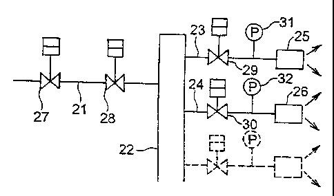
Fig. 1 is an explanatory view showing a construction
9a
CA 02399667 2002-08-23
of a gas turbine combustor apparatus of an embodiment
according to the present invention.
Fig. 2 is a longitudinal cross sectional view showing
one example of a structure of a gas turbine combustor
apparatus in the prior art.
Fig. 3 is a longitudinal cross sectional view showing
a structure of a dual fuel nozzle used in the gas turbine
combustor apparatus of Fig. 2.
DESCRIPTION OF THE PREFERRED EMBODIMENTS
Herebelow, a gas turbine combustor apparatus of the
present invention will be described more concretely based
on an embodiment shown in Fig. 1. It is to be noted that,
while a plurality of fuel supply systems are provided, only
two of them will be representatively taken for description.
In Fig. 1, numeral 21 designates a fuel supply pipe and
construction of the system is made such that fuel led through
the fuel supply pipe 21 enters fuel supply systems 23, 24
via a manifold 22 to be supplied into respective combustors
25, 26. A pressure regulating valve 27 and a flow regulating
valve 28 are provided in the fuel supply pipe 21. Also, flow
regulating valves 29, 30 and pressure gauges 31, 32 are
provided in the fuel supply systems 23, 24, respectively,
that connect to the combustors 25, 26.
Here, the construction of the entire system is made
CA 02399667 2002-08-23
such that the flow regulating valves 29, 30 provided in the
fuel supply systems 23, 24, respectively, are controlled
to be opened or closed so that pressures measured by the
pressure gauges 31, 32 provided in the fuel supply systems
23, 24, respectively, may become the same. By so effecting
the control, pressures in the fuel supply systems 23, 24,
through which the respective combustors 25, 26 are supplied
with fuel, are maintained to the same value and thereby a
uniform pre-mixture can be formed in each of the combustors.
In the gas turbine combustor apparatus of Fig. 1 as
described above, the construction is made so that the
pressures in the fuel supply systems connecting to the
respective combustors may become the same. However, if flow
meters are provided in the fuel supply systems instead of
the pressure gauges and the construction is made such that
the flow regulating valves of the respective fuel supply
systems are controlled to be opened or closed so that flow
rates measured by the flow meters may become the same, then
it is also possible to obtain the same effect.
Or, instead of the pressure gauges or the flow meters
as mentioned above, if thermometers are provided for
measuring temperatures at blade passing points downstream
of the respective combustors, or metal temperatures of
stationary blades downstream of the respective combustors,
or metal temperatures of the respective combustors and the
11
CA 02399667 2002-08-23
construction is made such that the flow regulating valves
of the respective fuel supply systems are controlled to be
opened or closed so that the temperatures so measured may
become the same, then it is also possible to obtain the same
effect.
In the above, while the description has been made
on controlling the control systems having respectively the
single pressure gauge, flow meter or thermometer, the
construction may be made such that at least two of the
mentioned control systems are provided and an optimal
solution is obtained by the method of least squares, so that
the flow regulating valve provided in each of the fuel supply
systems is optimally controlled. This is preferable for
forming a uniform pre-mixture in each of the combustors.
Furthermore, instead of using the pressure gauges
or the flow meters for controlling the flow regulating valves
in the plurality of fuel supply systems, the construction
may be made such that spectrum analyses are carried out on
measured values of inner pressure variations in each of the
21) combustors and the mentioned flow regulating valve
corresponding to the combustor in which the inner pressure
variations in a specific frequency range become a
predetermined value or more is controlled to be opened or
closed. For example, if the variation includes much of high
frequencies, the flow regulating valve is considered too
12
CA 02399667 2002-08-23
much throttled and the control is done so as to open the
flow regulating valve. Or, if the variation includes much
of low frequencies, it is considered an excess of fuel and
the control is done so as to throttle the flow regulating
valve. Thus, by controlling the flow regulating valve in
each of the fuel supply systems so that the inner pressure
variations in a specific frequency range may not become a
predetermined value or more in each of the combustors, a
uniform pre-mixture can be formed in each of the combustors.
In the above, while the invention has been described
based on the gas turbine combustor apparatus of the
embodiments, the invention is not limited to the embodiments
but may naturally be added with various modifications or
alterations as come within the scope of the invention defined
by the claims as appended herein.
For example, in the gas turbine combustor apparatus
of the embodiments according to the present invention as
described above, the construction may be made such that a
control unit is provided and, if an average value of openings
of the flow regulating valves provided in the respective
fuel supply systems exceeds a predetermined value, the
control unit adds a difference between the predetermined
value and the average value to the openings of the respective
flow regulating valves. Then, the opening and closing
control of the flow regulating valves can be made a more
13
CA 02399667 2002-08-23
stabilized one.
Or, in the gas turbine combustor apparatus of the
embodiments of the present invention, the construction may
be made such that a control unit is provided and, if a load
shutoff signal is given for the combustors, the control unit
gives signals so that openings of the respective flow
regulating valves may be set to a predetermined position.
Then, the flow regulating valve in each of the fuel supply
systems can be immediately set to such an opening position
11) as corresponds to the load shutoff operation.
Also, in the gas turbine combustor apparatus of the
embodiments of the present invention, the construction may
be made such that an alarm circuit is provided and, if the
flow regulating valve provided in each of the fuel supply
systems is opened or closed in excess of a predetermined
value, the alarm circuit gives an alarm of the unusual state
of the fuel systems. Then, the unusual state of the fuel
systems, such as an irregularity in the openings of the flow
regulating valves, is made known and an immediate
countermeasure can be taken.
14